Table of Contents
Table of Contents

Related Manuals for Bosch D9210B


Summary of Contents for Bosch D9210B
- Page 1 Access Control Interface Module D9210B Operation and Installation Guide...
- Page 2 D9210B D9210B Operation and Installation Guide 32206G Page 2 © 2002 Bosch Security Systems...
-
Page 3: Table Of Contents
Other Listings and Approvals............................12 Installation ......................................13 System Planning................................13 Procedure ..................................13 3.2.1 Step 1: Mounting the Enclosure and Installing the D9210B................. 13 3.2.2 Step 2: Pulling and Marking the Wires........................14 3.2.3 Step 3: Mounting ................................16 3.2.3.1 D9210BLC..................................16 3.2.3.2 D9210B ..................................... - Page 4 D9210B Contents LED Troubleshooting ...............................25 Appendix A: D9210B Terminal Quick Reference and Electrical Specifications .............. 27 Figures Figure 1: D9210B Access Control Interface Module........................ 9 Figure 2: Wiring Diagram for Typical D9210B Installation.....................15 Figure 3: Relay Installation ................................17 Figure 4: D9210B DIP Switch (Factory Settings)........................19 Figure 5: Power Supply and SDI Connections .........................20...
-
Page 5: Introduction
Other Literature Referenced Throughout this document, references will be made to other documentation. For a more complete and detailed description of the D9210B Access Control Interface Module, see the following table that lists the complete part number for ordering purposes. -
Page 6: Tips, Important Notes, Cautions And Warnings
U.S. Government Printing Office, Washington DC 20402, stock no. 004-000-00450-7. Regulatory Listings UL 294 UL 1076 UL 609 FCC 15B UL 365 UL 1610 UL 864 CSFM D9210B Operation and Installation Guide 32206G Page 6 © 2002 Bosch Security Systems... -
Page 7: D9210B Overview
SDI input and output. SDI A (yellow) receives data from the SDI A of the panel. SDI B (green) returns data to the SDI B of the panel. 12 VDC input. This input is used to power the D9210B and provides a connection for the 12 VDC reader and 12 VDC buzzer. -
Page 8: Access Levels
2.1.1.3 Access Levels Armed State rights Users can be prevented from access depending upon the armed state of the area that the D9210B is assigned to. M-indicates the user has access no matter what the armed state, P- indicates the user has access as long as the Area is perimeter armed or disarmed and D-indicates the user only has access when the area is completely disarmed. -
Page 9: Physical Overview
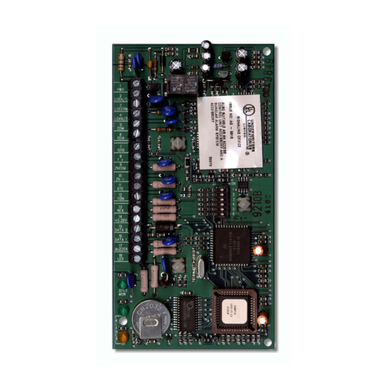
DIP Switch ZN + switches allows each unique D9210B to be programmed for a specific address. +5.20V DATA 0 PROM. The D9210B is controlled by a DATA 1 programmable read-only memory BUZZER microprocessor. PROM Diagnostic and Status LEDs. The Diagnostic and... -
Page 10: Displays And Reports
Materials Included Bosch Security Systems ships the D9210B Access Control Interface module pre-assembled from the factory with a power supply, in its own can, or as a unit less can. You will receive the following parts with your package depending upon what model is ordered, (see Section 2.5 Ordered Separately, p.11). -
Page 11: Ordered Separately
A) power supply, and (1) D9210B. It can be installed with another D9210BLC in a single D8103, D8109 or D8108A enclosure. D9210B: The D9210B is mounted in a 8 in. x 5 in. x 3 in. (20 cm x 13 cm x 7.6 cm) (HxWxD) enclosure and can be mounted as a standalone unit in the field. -
Page 12: Listings And Approval Information
Underwriters Laboratories (UL) The D9210B, when used with the D7412 or D9412 panels, is listed by UL for use as part of an Access Control System; Local, Police-Connect, Central Station, or Proprietary Burglar Alarm System; and a Commercial Fire Alarm System. In addition to the manual, refer to the D7412/D9412 installation documentation regarding Burglar Alarm Grades and Fire Alarm services supported. -
Page 13: Installation
Enclosure Placement. There is a 500 ft. (152 m) maximum distance allowed between the D9210B and Weigand card readers. Using 22 AWG (0.8 mm) wire, the D9210B may be remoted up to 2500 ft. (762 m) away from the control panel;... -
Page 14: Step 2: Pulling And Marking The Wires
Pulling and Marking the Wires Running wire. Use Table 4 to estimate the wire bundle size for your knockouts and where to mount the D9210B. Tag your wire runs to prevent confusion during installation and troubleshooting. Figure 2 shows the wiring for a typical D9210B installation. -
Page 15: Figure 2: Wiring Diagram For Typical D9210B Installation
A 24 VDC power supply may be used for the door strike if necessary. (See Figure 5) authority having jurisdiction (AHJ) prior to nstallation. Figure 2: Wiring Diagram for Typical D9210B Installation D9210B Operation and Installation Guide © 2002 Bosch Security Systems Page 15... -
Page 16: Step 3: Mounting
Installation 3.2.3 Mounting Do not install or replace a D9210B while it is connected to live power circuits. The D9210B should be powered down until it is ready to be tested. 3.2.3.1 D9210BLC Mount the D8103, D8109 or D8108A enclosure on a flat service. -
Page 17: Step 5: Door Lock, Terminals 2, 3 And 4
REX must not be used for emergency exit applications. NFPA 101 requires that a UL listed panic device be used to provide direct power from the standby power source. (see Figure 2: Wiring Diagram for Typical D9210B Installation, p.15 for wiring an emergency exit device). Check with your local Authority Having Jurisdiction (AHJ) prior to installing your system. -
Page 18: Step 9: Connecting The Card Reader, Terminals 12, 14, 15, 16, 17, And 18
* 12 V power from D9210B source Table 7: UL Listed Compatible Readers for the D9210B Readers can be mounted up to 500 ft. (152 m) from the D9210B module. A typical reader connection is shown in Figure 2: Wiring Diagram for Typical D9210B Installation, p.15. -
Page 19: Step 10: Setting The Dipswitch And Tagging The Unit
The D9412 panel supports up to eight door controllers using all eight address settings. The D7412 supports up to two door controllers using the first two address settings. Each D9210B uses one of eight addresses. Addresses can not be duplicated. Because the D9210B is always supervised, two D9210B modules having the same address will not function and SDI failures will occur. -
Page 20: Step 11 Connecting Power And Sdi, Terminals 1, 3, 5, 6, And 7
The dipswitch settings in Table 8: D9210B Dipswitch Settings, p.19 determine the address of the D9210B. At the top of the ACCESS Program Record Sheet (P/N:33208), the address number (noted next to the dipswitch setting in Figure 4: D9210B DIP Switch (Factory Settings), p.19) will determine which parameters for the door controller are sent. -
Page 21: Step 13: Testing The D9210B
Buzzer: The buzzer should have sounded on each strike activation. Also hold the door open past the normal shunt time and ensure the Extend Buzz functions. Reader: Depending on the reader, the reader LED will be red upon powering up the D9210B. During the above tests, it will turn green anytime the strike is activated. - Page 22 D9210B Installation Notes: D9210B Operation and Installation Guide 32206G Page 22 © 2002 Bosch Security Systems...
-
Page 23: Operation
D9210B Operation Operation Door Release Application The D9210B can be used for door RELAY release functions. When used in this configuration, the strike relay contacts must be supervised. This can be accomplished with the use D9210B of an end-of-line relay commonly AUX POWER used for smoke detectors. - Page 24 D9210B Operation Notes: D9210B Operation and Installation Guide 32206G Page 24 © 2002 Bosch Security Systems...
-
Page 25: Troubleshooting
D9210B Troubleshooting Troubleshooting LED Troubleshooting Use the following reader and D9210B LED patterns to troubleshoot the D9210B. It is important to use the Door Control function to validate actual door states when troubleshooting. Reader Action If Reader LED is then Door State is... - Page 26 D9210B Troubleshooting Notes: D9210B Operation and Installation Guide 32206G Page 26 © 2002 Bosch Security Systems...
-
Page 27: Appendix A: D9210B Terminal Quick Reference And Electrical Specifications
SDI A Data from the panel to the D9210B high impedance bi-directional differential bus SDI B Data back to the panel from the D9210B RS-485 @ 9600 baud Positive input for Tamper, normally open open collector input 1 k pull up V in <... - Page 28 © 2002 Bosch Security Systems 32206G 10/02 130 Perinton Parkway, Fairport, NY 14450-9199 USA Operation and Installation D9210B Customer Service: (800) 538-5807; Technical Support: (888) 886-6189 Guide Page 28 of 28...