Table of Contents
Quick Links
Table of Contents
Troubleshooting

Related Manuals for Yamaha YZFR1W(C)


Summary of Contents for Yamaha YZFR1W(C)
- Page 1 OWNER’S MANUAL YZFR1W(C) LIT-11626-20-53 4C8-28199-10...
- Page 2 EAU10041...
- Page 3 Yamaha has met these standards without reducing the performance or economy of operation of the motorcycle. To maintain these high standards, it is important that you and your Yamaha dealer pay close attention to the recommended maintenance schedules and operating instructions contained within this manual.
-
Page 4: Important Manual Information
This manual should be considered a permanent part of this motorcycle and should remain with it even if the motorcycle is subsequently sold. Yamaha continually seeks advancements in product design and quality. Therefore, while this manual contains the most current product information available at the time of printing, there may be minor discrepancies between your motorcycle and this manual. - Page 5 IMPORTANT MANUAL INFORMATION AND UNTIL YOU HAVE BEEN TRAINED IN SAFE AND PROPER RIDING TECHNIQUES. REGULAR INSPECTIONS AND CAREFUL MAINTENANCE, ALONG WITH GOOD RIDING SKILLS, WILL ENSURE THAT YOU SAFELY ENJOY THE CAPABILITIES AND THE RELIABILITY OF THIS MOTORCYCLE. *Product and specifications are subject to change without notice.
- Page 6 IMPORTANT MANUAL INFORMATION EAU10192 AFFIX DEALER LABEL HERE YZFR1W(C) OWNER’S MANUAL ©2006 by Yamaha Motor Corporation, U.S.A. 1st edition, September 2006 All rights reserved. Any reprinting or unauthorized use without the written permission of Yamaha Motor Corporation, U.S.A. is expressly prohibited.
-
Page 7: Table Of Contents
TABLE OF CONTENTS SAFETY INFORMATION ....1-1 PRE-OPERATION CHECKS ..... 4-1 Accessories and Location of important labels ...1-5 Pre-operation check list ....4-2 replacement parts ..... 6-24 Adjusting the clutch lever DESCRIPTION ........2-1 OPERATION AND IMPORTANT free play ........6-25 Left view ..........2-1 RIDING POINTS ........ - Page 8 Matte color caution ......7-1 Care ..........7-1 Storage ...........7-4 SPECIFICATIONS ......8-1 CONSUMER INFORMATION.....9-1 Identification numbers ....9-1 Reporting safety defects ....9-3 Motorcycle noise regulation ....9-4 Maintenance record ......9-5 YAMAHA MOTOR CORPORATION, U.S.A. STREET AND ENDURO MOTORCYCLE LIMITED WARRANTY ........9-7 YAMAHA EXTENDED SERVICE (Y.E.S.) ........9-9...
-
Page 9: Safety Information
SAFETY INFORMATION EAU10281 AND/OR WHEN MADE NECES- • Ride where other motorists can SARY BY MECHANICAL CONDI- see you. Avoid riding in another MOTORCYCLES SINGLE TIONS. motorist’s blind spot. TRACK VEHICLES. THEIR SAFE USE Many accidents involve inexperi- AND OPERATION ARE DEPENDENT Safe riding enced operators. - Page 10 Modifications made to this motorcycle other motorists can see you. the single most critical factor in the pre- not approved by Yamaha, or the re- The posture of the operator and vention or reduction of head injuries. moval of original equipment, may ren- passenger is important for proper Always wear an approved helmet.
- Page 11 Maximum load: been specifically designed for use on create instability due to improper 196 kg (432 lb) this motorcycle. Since Yamaha cannot weight distribution or aerody- test all other accessories that may be namic changes. If accessories When loading within this weight limit,...
- Page 12 SAFETY INFORMATION tor and may limit control ability, Always turn the engine off before or clothing, immediately wash the therefore, such accessories are leaving the motorcycle unattended affected area with soap and water not recommended. and remove the key from the main and change your clothes.
-
Page 13: Location Of Important Labels
SAFETY INFORMATION EAU10381 Location of important labels Please read the following important labels carefully before operating this vehicle. - Page 14 SAFETY INFORMATION California only CAUTION Cleaning with alkaline or acid cleaner, gasoline or solvent will damage windshield. Use neutral detergent. 5JW-00 California only California only HOW TO LAYOUT FUEL HOSES FUEL TANK FUEL PUMP FUEL FILTER PRESS. REGULATOR FUEL DELIVERY 2C0-2178A-00...
- Page 15 SAFETY INFORMATION WARNING BEFORE YOU OPERATE THIS VEHICLE, READ THE OWNER’S MANUAL AND ALL LABELS. ALWAYS WEAR AN APPROVED MOTORCYCLE HELMET, eye protection, and protectibe clothing. 290 kPa, {2.90 kgf/cm }, 42psi PREMIUM UNLEADED GASOLINE ONLY 91 Min. Pump Octane (R+M)/2 4C8-2118K-00 5VY-21668-00 3JJ-28446-A1...
-
Page 16: Description
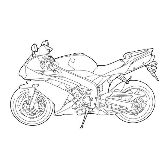
DESCRIPTION EAU10410 Left view 1. Fuse box (page 6-35) 8. Shock absorber assembly rebound damping force adjusting screw (page 3-19) 2. Front fork rebound damping force adjusting screw (page 3-17) 9. Shock absorber assembly spring preload adjusting ring (page 3-19) 3. -
Page 17: Right View
DESCRIPTION EAU10420 Right view 1. Luggage strap holder (page 3-21) 9. Engine oil level check window (page 6-13) 2. Helmet holder (page 3-16) 10.Engine oil filler cap (page 6-13) 3. Owner’s tool kit (page 6-1) 11.Rear brake fluid reservoir (page 6-27) 4. -
Page 18: Controls And Instruments
DESCRIPTION EAU10430 Controls and instruments 1. Clutch lever (page 3-12) 2. Left handlebar switches (page 3-11) 3. Main switch/steering lock (page 3-1) 4. Multi-function meter unit (page 3-5) 5. Front brake fluid reservoir (page 6-27) 6. Right handlebar switches (page 3-11) 7. -
Page 19: Instrument And Control Functions
INSTRUMENT AND CONTROL FUNCTIONS EAU10460 To lock the steering Main switch/steering lock NOTE: The headlights come on automatically when the engine is started and stay on until the key is turned to “OFF”, even if the engine stalls. EAU10660 All electrical systems are off. The key can be removed. -
Page 20: Indicator And Warning Lights
“LOCK” while the vehicle is moving, 9. Engine trouble warning light “ ” Yamaha dealer check the electrical cir- otherwise the electrical systems will cuit. be switched off, which may result in EAU11030 loss of control or an accident. - Page 21 If the warning light does not come on for a few seconds, and then go off, for a few seconds, then go off, have a have a Yamaha dealer check the elec- Yamaha dealer check the electrical cir- trical circuit.
- Page 22 INSTRUMENT AND CONTROL FUNCTIONS Coolant Display Conditions What to do temperature Under 39 °C Message “Lo” is displayed. OK. Go ahead with riding. (Under 103 °F) 40–116 °C Temperature is displayed. OK. Go ahead with riding. (104–242 °F) Stop the vehicle and allow it to idle until 117–139 °C Temperature display flashes.
-
Page 23: Multi-Function Meter Unit
This warning light comes on or flashes light and on how to set it.) when an electrical circuit monitoring the engine is defective. When this occurs, have a Yamaha dealer check the self- diagnosis system. (See page 3-5 for an explanation of the self-diagnosis de- vice.) - Page 24 INSTRUMENT AND CONTROL FUNCTIONS a speedometer (which shows the To switch the speedometer and ECA10031 CAUTION: riding speed) odometer/tripmeter displays be- a tachometer (which shows engine tween kilometers and miles, press Do not operate the engine in the ta- speed) the “SELECT”...
- Page 25 INSTRUMENT AND CONTROL FUNCTIONS 3. Push the “SELECT” button, and If the fuel level warning light comes on Standard measurement the minute digits will start flashing. (see page 3-2), the odometer display 1. Push the “RESET” button to start 4. Push the “RESET” button to set will automatically change to the fuel re- the stopwatch.
- Page 26 Do not operate the engine if it is matically displayed, even if the air have a Yamaha dealer check the vehi- overheated. intake temperature was displayed cle. prior to turning the key to “OFF”.
- Page 27 INSTRUMENT AND CONTROL FUNCTIONS ECA11590 Display brightness: NOTE: CAUTION: This function allows you to adjust In this mode, the right display shows the brightness of the displays and If the display indicates an error the current setting for each function tachometer to suit the outside code, the vehicle should be checked (except the shift timing indicator light...
- Page 28 INSTRUMENT AND CONTROL FUNCTIONS The indicator light will stay on set in increments of 500 r/min. From Be sure to set the deactivation when activated. (This setting 12000 r/min to 15000 r/min, the indica- function to a higher engine speed is selected when the indicator tor light can be set in increments of 200 than for the activation function,...
-
Page 29: Handlebar Switches
INSTRUMENT AND CONTROL FUNCTIONS EAU12347 EAU12400 ECA10050 Handlebar switches Dimmer switch “ ” CAUTION: Set this switch to “ ” for the high See page 5-1 for starting instruc- Left beam and to “ ” for the low beam. tions prior to starting the engine. EAU12460 Turn signal switch “... -
Page 30: Clutch Lever
INSTRUMENT AND CONTROL FUNCTIONS EAU12820 EAU12870 EAU33850 Clutch lever Shift pedal Brake lever 1. Clutch lever 1. Shift pedal 1. Brake lever 2. Brake lever position adjusting knob The clutch lever is located at the left The shift pedal is located on the left 3. -
Page 31: Brake Pedal
INSTRUMENT AND CONTROL FUNCTIONS it by aligning a groove on the adjusting EAU12941 EAU13072 Brake pedal Fuel tank cap knob with the “ ” mark on the brake lever. 1. Brake pedal 1. Fuel tank cap lock cover 2. Unlock. The brake pedal is on the right side of the motorcycle. -
Page 32: Fuel
Avoid spilling fuel on the hot en- as well as to the exhaust system. gine. Your Yamaha engine has been de- signed to use premium unleaded gaso- line with a pump octane number [(R+M)/2] of 91 or higher, or a research... -
Page 33: Catalytic Converter
10%. Gasohol ECA10700 CAUTION: containing methanol is not recom- mended by Yamaha because it can The following precautions must be cause damage to the fuel system or ve- observed to prevent a fire hazard or hicle performance problems. -
Page 34: Helmet Holders
INSTRUMENT AND CONTROL FUNCTIONS 2. Lift the front of the passenger seat EAU33870 Helmet holders and pull it forward. To install the passenger seat 1. Insert the projection on the rear of the passenger seat into the seat holder as shown, and then push the front of the seat down to lock it in place. -
Page 35: Adjusting The Front Fork
INSTRUMENT AND CONTROL FUNCTIONS To release a helmet from a helmet EAU14741 load thereby soften Adjusting the front fork holder suspension, turn the adjusting bolt on This front fork is equipped with spring Remove the passenger seat, remove each fork leg in direction (b). preload adjusting bolts, rebound damp- the helmet from the helmet holder, and NOTE:... -
Page 36: Specifications
INSTRUMENT AND CONTROL FUNCTIONS Rebound damping force Compression damping force ECA10100 CAUTION: Never attempt to turn an adjusting mechanism beyond the maximum or minimum settings. NOTE: Although the total number of clicks of a damping force adjusting mechanism may not exactly match the above spec- ifications due to small differences in 1. -
Page 37: Adjusting The Shock Absorber Assembly
INSTRUMENT AND CONTROL FUNCTIONS EAU42940 Spring preload Spring preload setting: Adjusting the shock absorber Minimum (soft): assembly This shock absorber assembly is Standard: equipped with a spring preload adjust- Maximum (hard): ing ring, a rebound damping force ad- justing screw, a compression damping force adjusting bolt (for fast compres- Rebound damping force sion damping) and a compression... - Page 38 INSTRUMENT AND CONTROL FUNCTIONS direction (a). To decrease the compres- Rebound damping setting: Compression damping setting (for sion damping force and thereby soften Minimum (soft): slow compression damping): the compression damping, turn the ad- 20 click(s) in direction (b)* Minimum (soft): Standard: 20 click(s) in direction (b)* justing bolt in direction (b).
-
Page 39: Luggage Strap Holders
EAU15181 EAU15281 Luggage strap holders EXUP system handling the shock absorber. The This model is equipped with Yamaha’s manufacturer cannot be held re- EXUP (EXhaust Ultimate Power valve) sponsible for property damage or system. This system boosts engine personal injury that may result from power by means of a valve that regu- improper handling. -
Page 40: Sidestand
INSTRUMENT AND CONTROL FUNCTIONS EAU15301 below and have a Yamaha dealer re- EAU15311 Sidestand Ignition circuit cut-off system pair it if it does not function proper- The sidestand is located on the left side The ignition circuit cut-off system (com- of the frame. - Page 41 5. Push the start switch. Does the engine start? The neutral switch may be defective. The motorcycle should not be ridden until checked by a Yamaha dealer. With the engine still running: 6. Move the sidestand up. 7. Keep the clutch lever pulled.
-
Page 42: Pre-Operation Checks
PRE-OPERATION CHECKS EAU15592 The condition of a vehicle is the owner’s responsibility. Vital components can start to deteriorate quickly and unexpectedly, even if the vehicle remains unused (for example, as a result of exposure to the elements). Any damage, fluid leakage or loss of tire air pressure could have serious consequences. -
Page 43: Pre-Operation Check List
• If necessary, add recommended coolant to specified level. 6-16 • Check cooling system for leakage. • Check operation. • If soft or spongy, have Yamaha dealer bleed hydraulic system. • Check brake pads for wear. Front brake • Replace if necessary. - Page 44 • Make sure that operation is smooth. • Check cable free play. Throttle grip 6-21, 6-30 • If necessary, have Yamaha dealer adjust cable free play and lubricate cable and grip housing. • Make sure that operation is smooth. Control cables 6-30 •...
-
Page 45: Operation And Important Riding Points
Yamaha dealer check the electrical cir- sciousness and death within a described on page 3-22. cuit. short time. Always make sure Never ride with the sidestand 3. -
Page 46: Shifting
OPERATION AND IMPORTANT RIDING POINTS ECA11130 EAU16671 ECA10260 Shifting CAUTION: CAUTION: For maximum engine life, always Even with the transmission in warm the engine up before starting the neutral position, do not off. Never accelerate hard when the coast for long periods of time engine is cold! with the engine off, and do not tow the motorcycle for long dis-... -
Page 47: Engine Break-In
OPERATION AND IMPORTANT RIDING POINTS 4. At the recommended shift points 3. Shift the transmission into the neu- EAU16841 Engine break-in shown in the following table, close tral position when the motorcycle There is never a more important period the throttle, and at the same time, is almost completely stopped. -
Page 48: Parking
If any engine trouble should oc- may overturn. cur during the engine break-in ECA10380 period, immediately have a CAUTION: Yamaha dealer check the vehi- Never park in an area where there cle. are fire hazards such as grass or other flammable materials. NOTE:... -
Page 49: Periodic Maintenance And Minor Repair
TRAINED AND EQUIPPED TO PER- certain maintenance work correctly. FORM THESE PARTICULAR SER- VICES. NOTE: If you do not have the tools or experi- ence required for a particular job, have a Yamaha dealer perform it for you. - Page 50 PERIODIC MAINTENANCE AND MINOR REPAIR EWA10340 WARNING Modifications approved Yamaha may cause loss of perfor- mance, excessive emissions, and render the vehicle unsafe for use. Consult a Yamaha dealer before at- tempting any changes. EWA12371 WARNING Do not touch either muffler bracket,...
-
Page 51: Periodic Maintenance Chart For The Emission Control System
• Check the air cut-off valve, reed Air induction sys- valve, and hose for damage. √ √ • Replace any damaged parts if necessary. * Since these items require special tools, data and technical skills, have a Yamaha dealer perform the service. -
Page 52: General Maintenance And Lubrication Chart
PERIODIC MAINTENANCE AND MINOR REPAIR EAU32183 General maintenance and lubrication chart INITIAL ODOMETER READINGS 600 mi 4000 mi 8000 mi 12000 mi 16000 mi 20000 mi ITEM ROUTINE (1000 km) (7000 km) (13000 km) (19000 km) (25000 km) (31000 km) 1 month 6 months 12 months... - Page 53 PERIODIC MAINTENANCE AND MINOR REPAIR INITIAL ODOMETER READINGS 600 mi 4000 mi 8000 mi 12000 mi 16000 mi 20000 mi ITEM ROUTINE (1000 km) (7000 km) (13000 km) (19000 km) (25000 km) (31000 km) 1 month 6 months 12 months 18 months 24 months 30 months...
- Page 54 Front and rear brake √ √ √ √ √ √ 25 * • Check operation. switches • Apply Yamaha chain and cable √ √ √ √ √ √ 26 * Control cables lube or engine oil SAE 10W-30 thoroughly.
- Page 55 • Adjust headlight beam. * Since these items require special tools, data and technical skills, have a Yamaha dealer perform the service. NOTE: From 24000 mi (37000 km) or 36 months, repeat the maintenance intervals starting from 8000 mi (13000 km) or 12 months.
- Page 56 PERIODIC MAINTENANCE AND MINOR REPAIR • Replace the brake hoses every four years and if cracked or damaged.
-
Page 57: Removing And Installing Cowlings And Panels
PERIODIC MAINTENANCE AND MINOR REPAIR EAU18712 Removing and installing cowl- ings and panels The cowlings and panels shown need to be removed to perform some of the maintenance jobs described in this chapter. Refer to this section each time a cowling or panel needs to be re- moved and installed. - Page 58 PERIODIC MAINTENANCE AND MINOR REPAIR 2. Fit the projections on the cowling into the slots and slide it forward. 1. Cowling B 1. Bolt 2. Quick fastener 2. Quick fastener screw 3. Cowling C 1. Slot 2. Disconnect the turn signal light 2.
- Page 59 PERIODIC MAINTENANCE AND MINOR REPAIR To install the cowling EAU36630 Panels C and D 1. Insert the projections into the slots, and then slide the cowling forward. To remove one of the panels Remove the screw and the quick fas- tener, and then pull the panel off as shown.
-
Page 60: Checking The Spark Plugs
Do not attempt to diagnose wipe off any grime from the spark plug such problems yourself. Instead, have threads. a Yamaha dealer check the vehicle. If a spark plug shows signs of electrode Tightening torque: Spark plug: erosion and excessive carbon or other 12.5 Nm (1.25 m·kgf, 9.0 ft·lbf) -
Page 61: Canister (For California Only)
PERIODIC MAINTENANCE AND MINOR REPAIR EAU19681 EAU19911 NOTE: Canister (for California only) Engine oil and oil filter car- If a torque wrench is not available when tridge installing a spark plug, a good estimate The engine oil level should be checked of the correct torque is 1/4–1/2 turn before each ride. - Page 62 2. Engine oil filter cartridge NOTE: An oil filter wrench is available at a 1. Engine oil level check window Yamaha dealer. 2. Maximum level mark 3. Minimum level mark 6. Apply a thin coat of engine oil to 4. Engine oil filler cap the O-ring of the new oil filter car- 1.
- Page 63 PERIODIC MAINTENANCE AND MINOR REPAIR Recommended engine oil: See page 8-1. Oil quantity: Without oil filter cartridge replace- ment: 2.90 L (3.07 US qt) (2.55 Imp.qt) With oil filter cartridge replacement: 3.10 L (3.28 US qt) (2.73 Imp.qt) ECA11620 CAUTION: 1.
-
Page 64: Coolant
If the oil level warning light flickers EAU42990 or remains on, immediately turn the To check the coolant level engine off and have a Yamaha dealer 1. Place the vehicle on a level sur- 1. Coolant reservoir check the vehicle. -
Page 65: Change Coolant
PERIODIC MAINTENANCE AND MINOR REPAIR If water has been added to the 3. Place a container under the engine coolant, have a Yamaha dealer to collect the used coolant. check the antifreeze content of 4. Remove the radiator cap. the coolant as soon as possible,... - Page 66 If water has been added to the 1. Coolant reservoir cap 2. Coolant reservoir coolant, have a Yamaha dealer 3. Bolt check the antifreeze content of 6-18...
-
Page 67: Replacing The Air Filter Element
15. Start the engine, and then check well supported. the vehicle for coolant leakage. If Do not tilt or pull the fuel tank coolant is leaking, have a Yamaha too much, otherwise the fuel dealer check the cooling system. hoses may come loose, which 16. - Page 68 6. Pull the air filter element out. are not damaged. If any fuel hose is damaged, do not start the engine. Have a Yamaha dealer replace the hose, other- wise fuel may leak. Make sure that the fuel hoses 1.
-
Page 69: Checking The Throttle Cable Free Play
To prevent this from occurring, the valve clearance must be adjusted by a Yamaha dealer at the intervals specified in the periodic maintenance and lubrication chart. 1. Throttle cable free play 1. -
Page 70: Tires
PERIODIC MAINTENANCE AND MINOR REPAIR EAU21750 evenly from side to side. Properly Tire air pressure (measured on cold Tires adjust the suspension for your load, tires): To maximize the performance, durabil- and check the condition and pres- 0–90 kg (0–198 lb): ity, and safe operation of your motor- Front: sure of your tires. - Page 71 Use only the tire valves and in it, or if the sidewall is cracked, con- valve cores listed below to tact a Yamaha dealer immediately and avoid tire deflation during a have the tire replaced. high-speed ride.
-
Page 72: Cast Wheels
Other tires may run fore each ride. If any damage is parts you choose for your vehicle the danger of bursting at super found, have a Yamaha dealer re- should be designed specifically for high speeds. place the wheel. Do not attempt... -
Page 73: Adjusting The Clutch Lever Free Play
NOTE: use of items which have not been If the specified clutch lever free play play approved by Yamaha. cannot be obtained as described above, proceed as follows. 1. Fully turn the adjusting bolt at the clutch lever in direction (a) to loos- en the clutch cable. -
Page 74: Adjusting The Rear Brake Light Switch
Checking the front and rear almost touches the brake disc, have a switch brake pads Yamaha dealer replace the brake pads The front and rear brake pads must be as a set. checked for wear at the intervals spec- ified in the periodic maintenance and... -
Page 75: Checking The Brake Fluid Level
However, if the Use only the recommended quality brake fluid level goes down sud- 1. Minimum level mark brake fluid, otherwise the rubber denly, have a Yamaha dealer Rear brake seals may deteriorate, causing check the cause. leakage and poor braking perfor- mance. -
Page 76: Changing The Brake Fluid
EAU22730 EAU22760 Changing the brake fluid Drive chain slack Have a Yamaha dealer change the The drive chain slack should be brake fluid at the intervals specified in checked before each ride and adjusted the NOTE after the periodic mainte- if necessary. -
Page 77: Cleaning And Lubricating The Drive Chain
PERIODIC MAINTENANCE AND MINOR REPAIR 3. Tighten the locknuts, then the axle EAU23022 NOTE: Cleaning and lubricating the nut to their specified torques. Using the alignment marks on each drive chain side of the swingarm, make sure that The drive chain must be cleaned and Tightening torques: both chain pullers are in the same posi- Locknut:... -
Page 78: Checking And Lubricating The Cables
If a cable is damaged maintenance chart. or does not move smoothly, have a Yamaha dealer check or replace it. Recommended lubricant: Yamaha Chain and Cable Lube or engine oil SAE 10W-30... -
Page 79: Checking And Lubricating The Brake And Clutch Levers
PERIODIC MAINTENANCE AND MINOR REPAIR EAU23140 EAU43070 Recommended lubricant: Checking and lubricating the Checking and lubricating the Lithium-soap-based grease (all-pur- brake and clutch levers shift pedal pose grease) Brake lever The operation of the shift pedal should be checked before each ride, and the Clutch lever shift pedal rod pivots should be lubricat- ed if necessary. -
Page 80: Checking And Lubricating The Sidestand
2. While applying the front brake, If the sidestand does not move up push down hard on the handlebars and down smoothly, have a Yamaha several times to check if the front dealer check or repair it. fork compresses and rebounds smoothly. -
Page 81: Checking The Steering
Securely support the vehicle so that fork does not operate smoothly, there is no danger of it falling over. have a Yamaha dealer check or re- pair it. 2. Hold the lower ends of the front fork legs and try to move them for- ward and backward. -
Page 82: Checking The Wheel Bearings
Batteries produce explosive hy- drogen gas. Therefore, keep To charge the battery sparks, flames, cigarettes, etc., Have a Yamaha dealer charge the bat- away from the battery and pro- tery as soon as possible if it seems to vide sufficient ventilation when have discharged. -
Page 83: Replacing The Fuses
If you do not have access to a CHILDREN. sealed-type (MF) battery charg- To access the main fuse er, have a Yamaha dealer The main fuse is located under the rider charge your battery. To store the battery seat and can be accessed as follows: 1. - Page 84 PERIODIC MAINTENANCE AND MINOR REPAIR 1. Main fuse 1. Rubber damper 1. Fuse box To access the fuel injection system fuse The fuel injection system fuse is locat- ed under the fuel tank and can be ac- cessed as follows: 1.
-
Page 85: Replacing A Headlight Bulb
50.0 A Headlight fuse: 4. If the fuse immediately blows 1. High beam headlight bulb 25.0 A again, have a Yamaha dealer 2. Low beam headlight bulb Signaling system fuse: check the electrical system. 7.5 A This model is equipped with quartz bulb Ignition fuse: headlights. - Page 86 6. Install the panel. of the bulb, and the bulb life will 7. Have a Yamaha dealer adjust the be adversely affected. Thor- headlight beam if necessary. oughly clean off any dirt and fin-...
- Page 87 PERIODIC MAINTENANCE AND MINOR REPAIR Headlight bulb Do not touch the glass part of the headlight bulb to keep it free from oil, otherwise the transpar- ency of the glass, the luminosity of the bulb, and the bulb life will be adversely affected.
-
Page 88: Tail/Brake Light
1. Remove the turn signal light lens 7. Have a Yamaha dealer adjust the If the tail/brake light does not come on, by removing the screw. headlight beam if necessary. have a Yamaha dealer check it. -
Page 89: Replacing The License Plate Light Bulb
PERIODIC MAINTENANCE AND MINOR REPAIR EAU24310 3. Remove the defective bulb by pull- EAU33910 Replacing the license plate Replacing an auxiliary light ing it out. light bulb bulb 4. Insert a new bulb into the socket. 1. Remove the license plate light unit This model is equipped with two auxil- 5. -
Page 90: Supporting The Motorcycle
PERIODIC MAINTENANCE AND MINOR REPAIR 3. Remove the socket (together with 7. Install the auxiliary light bulb cover EAU24350 Supporting the motorcycle the bulb) by pulling it out. by installing the quick fastener. Since this model is not equipped with a NOTE: centerstand, follow these precautions To install the quick fastener, push the... -
Page 91: Front Wheel
4. Remove the brake caliper on each To remove the front wheel side by removing the bolts. EWA10820 WARNING It is advisable to have a Yamaha dealer service the wheel. Securely support the motor- cycle so that there is no danger of it falling over. - Page 92 PERIODIC MAINTENANCE AND MINOR REPAIR 7. Tighten wheel axle pinch bolt B, NOTE: and then tighten pinch bolt A to the Make sure that there is enough space specified torque. between the brake pads before install- ing the brake calipers onto the brake discs.
-
Page 93: Rear Wheel
21 Nm (2.1 m·kgf, 15 ft·lbf) WARNING the swingarm. 5. Turn the drive chain slack adjust- It is advisable to have a Yamaha 12. While applying the front brake, ing bolts fully in direction (a) and dealer service the wheel. -
Page 94: Troubleshooting
ECA11070 CAUTION: self. However, should your motorcycle require any repair, take it to a Yamaha Do not apply the brake after the 1. Retainer dealer, whose skilled technicians have 2. Slot... -
Page 95: Troubleshooting Charts
Remove the spark plugs and check the electrodes. The engine does not start. Have a Yamaha dealer check the vehicle. Check the battery. 4. Battery The engine turns over The battery is good. - Page 96 Start the engine. If the engine overheats again, have a The coolant level Yamaha dealer check and repair the cooling system. is OK. NOTE: If coolant is not available, tap water can be temporarily used instead, provided that it is changed to the recommended coolant as soon as possible.
-
Page 97: Motorcycle Care And Storage
Rust and corrosion can develop matte colored finished parts. Be Cleaning even if high-quality components are sure to consult a Yamaha dealer for ECA15090 advice on what products to use be- used. A rusty exhaust pipe may go un- CAUTION: fore cleaning the vehicle. - Page 98 MOTORCYCLE CARE AND STORAGE Do not use any harsh chemical den part of the windshield to NOTE: products on plastic parts or the make sure that it does not leave Salt sprayed on roads in the winter may mufflers. Be sure to avoid using any marks.
- Page 99 Note that the thermally induced discoloring of the portion of the ex- Make sure that there is no oil or Consult a Yamaha dealer for advice on haust pipe leading into the titanium what products to use. wax on the brakes or tires.
-
Page 100: Storage
MOTORCYCLE CARE AND STORAGE EAU26201 3. Perform the following steps to pro- 4. Lubricate all control cables and the Storage tect the cylinders, piston rings, etc. pivoting points of all levers and from corrosion. pedals as well as of the side- Short-term a. -
Page 101: Specifications
SPECIFICATIONS Dimensions: Engine oil: Fuel: Overall length: Type: Recommended fuel: 2060 mm (81.1 in) YAMALUBE 4, SAE10W30 or SAE20W40 Premium unleaded gasoline only Overall width: Fuel tank capacity: 720 mm (28.3 in) 18.0 L (4.76 US gal) (3.96 Imp.gal) Overall height: Fuel reserve amount: 0°... - Page 102 SPECIFICATIONS Gear ratio: Manufacturer/model: Rear wheel: 1st: PIRELLI/DIABLO CORSA L Wheel type: 38/15 (2.533) Manufacturer/model: Cast wheel 2nd: MICHELIN/Pilot POWER Rim size: 33/16 (2.063) Loading: 17M/C x MT6.00 3rd: Maximum load: Front brake: 37/21 (1.762) 196 kg (432 lb) Type: 4th: (Total weight of rider, passenger, cargo and Dual disc brake...
- Page 103 SPECIFICATIONS Electrical system: Turn signal indicator light: Ignition system: Fuel level warning light: Transistorized coil ignition (digital) Charging system: Coolant temperature warning light: AC magneto Battery: Engine trouble warning light: Model: YTZ10S Shift timing indicator light: Voltage, capacity: 12 V, 8.6 Ah Fuses: Headlight: Main fuse:...
-
Page 104: Consumer Information
Record the key identification number, vehicle identification number and mod- el label information in the spaces pro- vided below for assistance when ordering spare parts from a Yamaha dealer or for reference in case the vehi- cle is stolen. KEY IDENTIFICATION NUMBER: 1. - Page 105 (See page 3-15.) Record the information on this la- bel in the space provided. This informa- tion will be needed when ordering spare parts from a Yamaha dealer. EWA12371 WARNING Do not touch either muffler bracket,...
-
Page 106: Reporting Safety Defects
If you believe that your vehicle has a defect which could cause a crash or could cause injury or death, you should immediately inform the National Highway Traffic Safety Administration (NHTSA) in addition to notifying Yamaha Motor Corporation, U.S.A. If NHTSA receives similar complaints, it may open an investigation, and if it finds that a safety defect exists in a group of vehicles, it may order a recall and remedy campaign. -
Page 107: Motorcycle Noise Regulation
CONSUMER INFORMATION EAU26560 Motorcycle noise regulation TAMPERING WITH NOISE CONTROL SYSTEM PROHIBITED: Federal law prohibits the following acts or the causing thereof: (1) The removal or rendering inoperative by any person other than for purposes of maintenance, repair, or replacement of any device or element of design incorporated into any new ve- hicle for the purpose of noise control prior to its sale or delivery to the ultimate purchaser or while it is in use or (2) the use of the vehicle after such device or element of design has been removed or rendered inoperative by any person. -
Page 108: Maintenance Record
CONSUMER INFORMATION EAU26632 Maintenance record Copies of work orders and/or receipts for parts purchased and installed on your vehicle will be required to document that maintenance has been completed in accordance with the emissions warranty. The chart below is printed only as a reminder that maintenance work is required. - Page 109 CONSUMER INFORMATION Maintenance Date of Servicing dealer Mileage Remarks interval service name and address 36000 mi (55000 km) or 54 months 40000 mi (61000 km) or 60 months...
-
Page 110: Yamaha Motor Corporation, U.s.a. Street And Enduro Motorcycle Limited Warranty
CONSUMER INFORMATION EAU26663 YAMAHA MOTOR CORPORATION, U.S.A. STREET AND ENDURO MOTORCYCLE LIMITED WARRANTY Yamaha Motor Corporation, U.S.A. hereby warrants that CUSTOMER’S RESPONSIBILITY under this Engine new Yamaha motorcycles will be free from defects in warranty shall be to: Displacement Period... - Page 111 CUSTOMER SERVICE What costs are my responsibility during the warranty period? If your machine requires warranty service, you must take it to any authorized Yamaha The customer’s responsibility includes all costs of normal maintenance services, motorcycle dealer within the continental United States. Be sure to bring your warranty non-warranty repairs, accident and collision damages, and oil, oil filters, air filters, registration card or other valid proof of the original date of purchase.
-
Page 112: Yamaha Extended Service (Y.e.s.)
This excellent Y.E.S. plan coverage is only available to dealer to see how comforting uninterrupted factory- Yamaha owners like you, and only while your Yamaha is still backed protection can be. within the Yamaha Limited Warranty period. So visit your authorized Yamaha dealer to get all the facts. - Page 113 Yamaha Limited Warranty expires. A special note: If visiting your dealer isn’t convenient, contact Yamaha with your Primary ID number (your frame number). We’ll be happy to help you get the Y.E.S. coverage you need.
- Page 114 INDEX Accessories and replacement parts..6-24 Front and rear brake pads, checking..6-26 Neutral indicator light ......3-2 Air filter element, replacing ....6-19 Front fork, adjusting......3-17 Noise regulation ........9-4 Auxiliary light bulb, replacing ....6-41 Front fork, checking ......6-32 Fuel............
- Page 115 INDEX Throttle grip and cable, checking and lubricating..... 6-30 Tires............6-22 Tool kit ............ 6-1 Troubleshooting........6-46 Troubleshooting charts ......6-47 Turn signal indicator lights ...... 3-2 Turn signal light bulb, replacing.... 6-40 Turn signal switch......... 3-11 Valve clearance ........6-21 Vehicle identification number....
- Page 118 YAMAHA MOTOR CO., LTD. PRINTED ON RECYCLED PAPER PRINTED IN JAPAN 2006.10-4.2×1 CR...