HP 1155 Maintenance And Service Manual
Maintenance & service guide hp 1155 all-in-one business pc
Hide thumbs
Also See for 1155:
- User manual (74 pages) ,
- Illustrated parts & service map (3 pages) ,
- Overview (13 pages)
Table of Contents
Quick Links
Table of Contents

Related Manuals for HP 1155


Summary of Contents for HP 1155
- Page 1 Maintenance & Service Guide HP 1155 All-in-One Business PC...
- Page 2 No part of this document may be photocopied, reproduced, or translated to another language without the prior written consent of Hewlett-Packard Company. Maintenance & Service Guide HP 1155 All-in-One Business PC First Edition (April 2013) Document Part Number: 730783-001...
-
Page 3: About This Book
About This Book WARNING! Text set off in this manner indicates that failure to follow directions could result in bodily harm or loss of life. CAUTION: Text set off in this manner indicates that failure to follow directions could result in damage to equipment or loss of information. -
Page 4: Table Of Contents
Table of contents 1 Product Features ............................1 Overview .............................. 1 Front Components ..........................2 Side Components ..........................3 Rear Components ..........................4 2 Installing and Customizing the Software ...................... 5 Activating and customizing the software ....................5 Activating the Windows Operating System ................5 Downloading Windows 8 updates .................. - Page 5 Generating Static ....................... 23 Preventing Electrostatic Damage to Equipment ..............24 Personal Grounding Methods and Equipment ..............24 Grounding the Work Area ....................25 Recommended Materials and Equipment ................25 Operating Guidelines .......................... 26 Routine Care ............................26 General Cleaning Safety Precautions ................26 Cleaning the Computer Case ....................
- Page 6 Hard Drive Cables and Connector ..................... 61 Fan ..............................63 Side I/O Cover ............................ 65 Webcam Module ..........................67 System Board Cover .......................... 69 Display Cable ............................. 71 System Board ............................. 73 Security Bracket ..........................74 Front Bezel ............................75 Display Panel .............................
- Page 7 Appendix C Backup and recovery in Windows 8 ..................123 Backing up your information ......................123 Performing a system recovery ......................124 Using the Windows recovery tools ................... 124 Using f11 recovery tools ....................125 Using Windows 8 operating system media (purchased separately) ........ 125 Appendix D POST Error Messages ......................
-
Page 8: Product Features
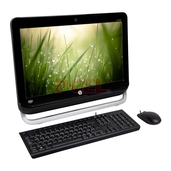
Product Features Overview HP Pro 1105 All-in-One Business PC offers the following features: ● Integrated All-in-One form factor ● 18.5-inch, WLED, diagonal widescreen HD (720p) anti-glare display (non-touch) ● Adjustable tilt stand ● Integrated ATI Radeon HD 7310, Microsoft® DirectX®6 11 capable ●... -
Page 9: Front Components
Front Components Component Component Dual microphones 18.5-inch diagonal widescreen LCD HD anti-glare display Low-light webcam Stereo speakers Chapter 1 Product Features... -
Page 10: Side Components
Side Components Component Component Power button 6-in-1 media card reader Optical disk drive (2) USB 3.0 Port Hard disk drive LED Indicator Microphone port Media card reader LED Indicator Headphone port Side Components... -
Page 11: Rear Components
Rear Components Component Component Adjustable tilt stand Security lock slot Power connector LED Indicator Line-out port Power connector RJ-45 ethernet port (4) USB 2.0 ports Chapter 1 Product Features... -
Page 12: Installing And Customizing The Software
Installing and Customizing the Software If your computer was not shipped with a Microsoft operating system, some portions of this documentation do not apply. Additional information is available in online help after you install the operating system. CAUTION: Do not add optional hardware or third-party devices to the computer until the operating system is successfully installed. -
Page 13: Downloading Windows 8 Updates
Downloading Windows 8 updates Microsoft may release updates to the operating system. To help keep the computer running optimally, HP recommends checking for the latest updates during the initial installation and periodically throughout the life of the computer. Run Windows Update as soon as possible after you set up your computer. Point to the upper-right or lower-right corner of the Start screen to display the charms. -
Page 14: Computer Setup (F10) Utility
Computer Setup (F10) Utility Computer Setup (F10) Utilities Use Computer Setup (F10) Utility to do the following: ● Change factory default settings. ● Set the system date and time. ● Set, view, change, or verify the system configuration, including settings for processor, graphics, memory, audio, storage, communications, and input devices. -
Page 15: Using Computer Setup (F10) Utilities
● Solve system configuration errors detected but not automatically fixed during the Power-On Self- Test (POST). ● Replicate the system setup by saving system configuration information on a USB device and restoring it on one or more computers. ● Execute self-tests on a specified ATA hard drive (when supported by drive). ●... -
Page 16: Computer Setup-File
Computer Setup—File NOTE: Support for specific Computer Setup options may vary depending on the hardware configuration. Table 3-2 Computer Setup—File Option Description System Information Lists: ● Product name ● SKU number ● Processor type/speed/stepping ● Cache size (L1/L2/L3) (dual core processors have this listed twice) ●... -
Page 17: Computer Setup-Storage
Computer Setup—Storage NOTE: Support for specific Computer Setup options may vary depending on the hardware configuration. Table 3-3 Computer Setup—Storage Option Description Device Configuration Lists all installed BIOS-controlled storage devices. When a device is selected, detailed information and options are displayed. The following options may be presented: ●... - Page 18 Table 3-3 Computer Setup—Storage (continued) Storage Options eSATA Port Allows you to set a SATA port as an eSATA port for use with an external drive. Default is enabled. This setting affects only the port with the black connector, labeled as eSATA on the system board. This port should have the eSATA back panel connector attached to use eSATA drives.
- Page 19 Table 3-3 Computer Setup—Storage (continued) DPS Self-Test Allows you to execute self-tests on ATA hard drives capable of performing the Drive Protection System (DPS) self-tests. NOTE: This selection will only appear when at least one drive capable of performing the DPS self-tests is attached to the system.
-
Page 20: Computer Setup-Security
Computer Setup—Security NOTE: Support for specific Computer Setup options may vary depending on the hardware configuration. Table 3-4 Computer Setup—Security Option Description Setup Password Allows you to set and enable a setup (administrator) password. NOTE: If the setup password is set, it is required to change Computer Setup options, flash the ROM, and make changes to certain plug and play settings under Windows. - Page 21 Table 3-4 Computer Setup—Security (continued) Slot Security Allows you to disable any PCI or PCI Express slot. Default is enabled. Network Boot Enables/disables the computer’s ability to boot from an operating system installed on a network server. (Feature available on NIC models only; the network controller must be either a PCI expansion card or embedded on the system board.) Default is enabled.
- Page 22 Table 3-4 Computer Setup—Security (continued) System Security Data Execution Prevention (enable/disable) - Helps prevent operating system security breaches. (these options are Default is enabled. hardware dependent) SVM CPU Virtualization (enable/disable). Controls the virtualization features of the processor. Changing this setting requires turning the computer off and then back on. Default is disabled. Virtualization Technology (VTx) (enable/disable) - Controls the virtualization features of the processor.
- Page 23 Table 3-4 Computer Setup—Security (continued) DriveLock Security Allows you to assign or modify a master or user password for hard drives. When this feature is enabled, the user is prompted to provide one of the DriveLock passwords during POST. If neither is successfully entered, the hard drive will remain inaccessible until one of the passwords is successfully provided during a subsequent cold-boot sequence.
-
Page 24: Computer Setup-Power
Computer Setup—Power NOTE: Support for specific Computer Setup options may vary depending on the hardware configuration. Table 3-5 Computer Setup—Power Option Description ● OS Power Idle Power Savings—Extended/Normal. Allows certain operating systems to decrease the Management processors power consumption when the processor is idle. Default is extended. ●... -
Page 25: Computer Setup-Advanced
Computer Setup—Advanced NOTE: Support for specific Computer Setup options may vary depending on the hardware configuration. Table 3-6 Computer Setup—Advanced (for advanced users) Option Heading Power-On Options Allows you to set: ● POST mode (QuickBoot, Clear Memory, FullBoot, or FullBoot Every x Days). ◦... - Page 26 Table 3-6 Computer Setup—Advanced (for advanced users) (continued) BIOS Power-On Allows you to set the computer to turn on automatically at a time you specify. Onboard Devices Allows you to set resources for or disable Legacy devices. Select the Legacy device's IRQ, DMA, and I/O Range. The settings may not take effect for all operating systems.
-
Page 27: Recovering The Configuration Settings
Table 3-6 Computer Setup—Advanced (for advanced users) (continued) VGA Configuration Displayed only if there is an add-in video card in the system. Allows you to specify which VGA controller will be the “boot” or primary VGA controller. AMT Configuration Allows you to set: ●... -
Page 28: Serial Ata (Sata) Drive Guidelines And Features
Serial ATA (SATA) Drive Guidelines and Features NOTE: HP only supports the use of SATA hard drives on these models of computer. No Parallel ATA (PATA) drives are supported. SATA Hard Drives Serial ATA Hard Drive Characteristics Number of pins/conductors in data cable Number of pins in power cable Maximum data cable length 39.37 in (100 cm) -
Page 29: Smart Ata Drives
SMART ATA Drives The Self Monitoring Analysis and Recording Technology (SMART) ATA drives for the HP Personal Computers have built-in drive failure prediction that warns the user or network administrator of an impending failure or crash of the hard drive. The SMART drive tracks fault prediction and failure indication parameters such as reallocated sector count, spin retry count, and calibration retry count. -
Page 30: Routine Care, And Disassembly Preparation
Routine Care, and Disassembly Preparation This chapter provides general service information for the computer. Adherence to the procedures and precautions described in this chapter is essential for proper service. CAUTION: When the computer is plugged into an AC power source, voltage is always applied to the system board. -
Page 31: Preventing Electrostatic Damage To Equipment
Removing DIPs* from vinyl tray 2,000 V 4,000 V 11,500 V Removing DIPs* from Styrofoam 3,500 V 5,000 V 14,500 V Removing bubble pack from PCB 7,000 V 20,000 V 26,500 V Packing PCBs in foam-lined box 5,000 V 11,000 V 21,000 V *These are then multi-packaged inside plastic tubes, trays, or Styrofoam. -
Page 32: Grounding The Work Area
Grounding the Work Area To prevent static damage at the work area, use the following precautions: ● Cover the work surface with approved static-dissipative material. Provide a wrist strap connected to the work surface and properly grounded tools and equipment. ●... -
Page 33: Operating Guidelines
Operating Guidelines To prevent overheating and to help prolong the life of the computer: ● Keep the computer away from excessive moisture, direct sunlight, and extremes of heat and cold. ● Operate the computer on a sturdy, level surface. Leave a 10.2-cm (4-inch) clearance on all vented sides of the computer and above the monitor to permit the required airflow. -
Page 34: Cleaning The Keyboard
To clean the computer case, follow the procedures described below: ● To remove light stains or dirt, use plain water with a clean, lint-free cloth or swab. ● For stronger stains, use a mild dishwashing liquid diluted with water. Rinse well by wiping it with a cloth or swab dampened with clear water. -
Page 35: Cleaning The Mouse
Cleaning the Mouse Before cleaning the mouse, ensure that the power to the computer is turned off. ● Clean the mouse ball by first removing the retaining plate and the ball from the housing. Pull out any debris from the ball socket and wipe the ball with a clean, dry cloth before reassembly. ●... -
Page 36: Hard Drives
Hard Drives Handle hard drives as delicate, precision components, avoiding all physical shock and vibration. This applies to failed drives as well as replacement spares. ● If a drive must be mailed, place the drive in a bubble-pack mailer or other suitable protective packaging and label the package “Fragile: Handle With Care.”... -
Page 37: Illustrated Parts Catalog
Illustrated parts catalog Computer major components Chapter 6 Illustrated parts catalog... - Page 38 Item Description Spare part number Front bezel 729648-001 Display panels (18.5-inch, WLED, non-ZBD, 200 nits) 710538-001 710539-001 710540-001 Rear cover (does not include stand) 669985-001 Foot assembly 669986-001 Side I/O panel 729649-001 Stand 669988-001 Mylar, for use on stand hinge (not illustrated) 669994-001 Computer major components...
-
Page 39: Cables
Cables Description Spare part number Display cable (LVDS) 669996-001 Optical drive cable 669998-001 Hard drive cable 669997-001 Webcam cable 669995-001 Antenna (not illustrated) 669974-001 Backlight cable for use with AUO and CMI display panels 710536-001 Backlight cable for use with LG display panels 710537-001 Chapter 6 Illustrated parts catalog... -
Page 40: Boards
Boards Description Spare part number System board with AMD E1-1500 processor, USB 3.0 (includes heat sink, gasket, 703642-001 processor, replacement thermal material) Models without Windows 8 728286-001 Windows 8 Standard 728286-501 Windows 8 Professional 728286-601 Backlight controller 710541-001 WLAN module (802.11b/g/n) Ralink RT3290LE 802.11bgn 1x1 Wi-Fi and Bluetooth 4.0 Combo Adapter (WLAN 701399-001 module) -
Page 41: Misc Parts
Misc Parts Description Spare part number Fan/blower 669981-001 Speaker Kit, includes left and right speakers 678227-001 Rubber grommet (for use in hard drive cage) 669991-001 Mouse (USB, optical; not illustrated) 596410-001 HP Business Digital Headset (not illustrated) 642738-001 Keyboard (not illustrated) USB (United States) 655571-001 USB (Latin America Spanish) -
Page 42: Mass Storage Devices (Not Illustrated)
Mass storage devices (not illustrated) Description Spare part number Optical drive HP SuperMulti DVD Writer Drive (includes bezel) 657958-001 Hard drives 1-TB 621418-001 750-GB 632938-001 500-GB 621421-001 320-GB 621420-001 250-GB 621419-001 Sequential part number listing Spare part Description number 596410-001 Mouse, USB, optical 621418-001 Hard drive, 1-TB... - Page 43 Spare part Description number 669997-001 Hard drive cable 669998-001 Optical drive cable 678227-001 Speaker Kit, includes left and right speakers 689372-001 Memory module, 2-GB (PC3-12800) 689373-001 Memory module, 4-GB (PC3-12800) 701396-001 Ralink RT5390R 802.11bgn 1x1 Wi-Fi Adapter (WLAN module) 701399-001 Ralink RT3290LE 802.11bgn 1x1 Wi-Fi and Bluetooth 4.0 Combo Adapter (WLAN module) 708630-161 Keyboard, wireless for use in Latin America...
-
Page 44: Removal And Replacement Procedures All-In One (Aio) Chassis
Removal and Replacement Procedures All-in One (AIO) Chassis The following sections provide information about disassembling various components of the computer. Preparing to Disassemble the Computer To avoid injury and equipment damage, always complete the following steps in order, when opening the computer. -
Page 45: Rear Cover
Rear Cover Description Spare part number Rear cover 669985-001 Remove the main rear cover to access internal components. The cover is secured by three Phillips screws – two captive in the bottom corners, one non-captive above the stand. To remove the rear cover: Prepare the computer for disassembly (see Preparing to Disassemble the Computer on page... -
Page 46: Stand
Stand Description Spare part number Stand 669988-001 The stand is secured with four screws that you can remove from the inside of the rear cover. To remove the stand: Prepare the computer for disassembly (see Preparing to Disassemble the Computer on page 37). - Page 47 Slide the stand bracket through the slot in the rear cover, and then remove the stand from the rear cover. To replace the stand, reverse the removal procedures. Chapter 7 Removal and Replacement Procedures All-in One (AIO) Chassis...
-
Page 48: Foot Assembly
Foot assembly Description Spare part number Foot assembly 669986-001 The foot assembly is secured with six screws. On each side, the inside screw is smaller than the two outside screws. To remove the foot assembly: Prepare the computer for disassembly (see Preparing to Disassemble the Computer on page 37). - Page 49 Remove the six screws that secure the foot assembly to the computer. Lift the foot assembly from the computer. To replace the foot assembly, reverse the removal procedures. Chapter 7 Removal and Replacement Procedures All-in One (AIO) Chassis...
-
Page 50: Memory Cover
Memory Cover Remove the memory cover to access the memory modules (SODIMMs), WLAN module, and RTC battery. The cover is secured by one captive Phillips screws. To remove the memory cover: Prepare the computer for disassembly (see Preparing to Disassemble the Computer on page 37). - Page 51 Lift the cover off the computer. To replace the memory cover, reverse the removal procedures. Chapter 7 Removal and Replacement Procedures All-in One (AIO) Chassis...
-
Page 52: Memory
Memory Description Spare part number 4 GB (PC3-12800) 689373-001 2 GB (PC3-12800) 689372-001 1 GB (PC3-10600) 646808-001 The memory modules are located under the memory cover. The computer has two memory slots. The computer comes with double data rate 3 synchronous dynamic random access memory (DDR3- SDRAM) small outline dual inline memory modules (SODIMMs). - Page 53 In addition, the computer supports: ● 512-Mbit, 1-Gbit, and 2-Gbit non-ECC memory technologies ● single-sided and double-sided SODIMMS ● SODIMMs constructed with x8 and x16 devices; SODIMMs constructed with x4 SDRAM are not supported NOTE: The system will not operate properly if you install unsupported SODIMMs. There are two memory sockets on the system board located behind the memory access panel.
-
Page 54: Wlan Module
WLAN Module Description Spare part number Ralink RT5390R 802.11bgn 1x1 Wi-Fi Adapter (WLAN module) 701396-001 Ralink RT3290LE 802.11bgn 1x1 Wi-Fi and Bluetooth 4.0 Combo Adapter (WLAN module) 701399-001 The WLAN module is secured with one screw and has one connected antenna. The module is located under the memory cover. - Page 55 Lift the module to a 45-degree angle, and then pull it away to remove it from the socket (3). To install the WLAN module, reverse the removal procedures. NOTE: WLAN modules are designed with a notch to prevent incorrect insertion. Chapter 7 Removal and Replacement Procedures All-in One (AIO) Chassis...
-
Page 56: Rtc Battery
RTC Battery The RTC battery is located under the memory cover. To remove the RTC battery: Prepare the computer for disassembly (see Preparing to Disassemble the Computer on page 37). Remove the rear cover (see Rear Cover on page 38). Remove the memory cover (see Memory Cover on page 43). - Page 57 To insert the new battery, slide one edge of the replacement battery under the holder’s lip with the positive side up. Push the other edge down until the clamp snaps over the other edge of the battery (2). Figure 7-1 Removing and Replacing a coin cell battery Chapter 7 Removal and Replacement Procedures All-in One (AIO) Chassis...
-
Page 58: Backlight Controller
Backlight Controller Description Spare part number Backlight controller 710541-001 The backlight controller is located on the left side of the computer. It is secured with two screws and has three connectors. To remove the backlight controller: Prepare the computer for disassembly (see Preparing to Disassemble the Computer on page 37). - Page 59 Lift the backlight controller board from the computer (3). To install the backlight controller board, reverse the removal procedures. Multiple display panels are available for this computer. The panels use the same backlight controller board spare part. You must position the jumper on the backlight controller board based on the display panel installed.
-
Page 60: Speakers
Speakers Description Spare part number Speaker Kit, includes left and right speakers 678227-001 The speakers are located at the bottom of the computer. Two separate speakers are each secured by two screws and have separate cables and system board connectors. To remove the speakers: Prepare the computer for disassembly (see Preparing to Disassemble the Computer... - Page 61 Remove two screws (2) that secure the left speaker to the computer, and then lift the speaker from the computer (3). Remove two screws (1) that secure the right speaker to the computer, and then lift the speaker from the computer (2). Use the following image to determine correct routing for the speaker cables.
-
Page 62: Optical Drive
Optical Drive Description Spare part number HP SuperMulti DVD Writer Drive (includes bezel) 657958-001 The optical drive is located on the left side of the computer (viewed from behind) under the backlight controller board. It is secured with one screw. To remove the optical drive: Prepare the computer for disassembly (see Preparing to Disassemble the Computer... - Page 63 Use the bracket (2) to push the drive out of the bay, and then slide the drive out of the computer (3). To install an optical drive, reverse the removal procedures. Chapter 7 Removal and Replacement Procedures All-in One (AIO) Chassis...
-
Page 64: Optical Drive Cables And Connector
Optical Drive Cables and Connector Description Spare part number Optical drive connector cable 669998-001 The optical drive connector is secured with two screws and has two cables that connect to the system board. To remove the optical drive connector: Prepare the computer for disassembly (see Preparing to Disassemble the Computer on page 37). - Page 65 Remove the connector from the computer. To install the optical drive connector, reverse the removal procedures. Chapter 7 Removal and Replacement Procedures All-in One (AIO) Chassis...
-
Page 66: Hard Drive
Hard Drive Description Spare part number 1-TB 621418-001 750-GB 632938-001 500-GB 621421-001 320-GB 621420-001 250-GB 621419-001 The hard drive is located on the left side of the computer (viewed from behind). The drive is secured with one captive screw and is housed in a removable cage. Prepare the computer for disassembly (see Preparing to Disassemble the Computer on page... - Page 67 Grasp the handle on top of the hard drive cage and slide the cage toward the outer edge of the computer (2), then lift the cage out of the computer (3). Remove the four mounting Phillips screws (1) that secure the drive to the cage. Do not remove the blue rubber grommets behind each screw.
-
Page 68: Hard Drive Cables And Connector
NOTE: Make sure the grommets are not broken or missing before installing the hard drive. Replacement grommets are available using spare part number 669991-001. Hard Drive Cables and Connector Description Spare part number Hard drive connector cable 669997-001 The hard drive connector is secured with two screws and has two cables that connect to the system board. - Page 69 Remove the connector from the computer (3). To install the hard drive connector, reverse the removal procedures. Chapter 7 Removal and Replacement Procedures All-in One (AIO) Chassis...
-
Page 70: Fan
Description Spare part number 669981-001 The fan is located in the middle of the computer. It is covered by a bracket and is secured with two screws. To remove the fan: Prepare the computer for disassembly (see Preparing to Disassemble the Computer on page 37). - Page 71 Remove the two screws (1) that secure the fan bracket to the computer, and then lift the bracket from the computer (2). Disconnect the fan cable (1) from the system board connector. Remove the three screws (2) that secure the fan to the computer. Lift the fan slightly, and then slide the fan assembly away from the system board and remove it from the computer (3).
-
Page 72: Side I/O Cover
Side I/O Cover Description Spare part number Side I/O cover 729649-001 The side I/O cover is located on the right side of the computer (viewed from behind). Press the tabs to remove it. To remove the side I/O cover: Prepare the computer for disassembly (see Preparing to Disassemble the Computer on page 37). - Page 73 Press the tab on the right side of the cover (1), and then pull the cover up and away from the computer (2). NOTE: To help disengage the panel, you can press the tab on the left side of the panel when pulling it away from the computer to remove it.
-
Page 74: Webcam Module
Webcam Module Description Spare part number Webcam module 710544-001 The webcam module is located at the top of the computer. It is secured with tabs (no screws) and has one connector. To remove the webcam module: Prepare the computer for disassembly (see Preparing to Disassemble the Computer on page 37). - Page 75 Disconnect the cable from the module (3), and then remove the module from the computer. If you need to remove the webcam cable, disconnect the cable from the webcam module (1), remove the cable from the metal clips built into the computer (2), disconnect the cable from the system board (3), and then remove the cable from the computer.
-
Page 76: System Board Cover
System Board Cover The system board cover protects the system board. It is secured with four screws. To remove the system board cover: Prepare the computer for disassembly (see Preparing to Disassemble the Computer on page 37). Remove the rear cover (see Rear Cover on page 38). - Page 77 Lift the outer side of the cover up to a 45-degree angle, and then lift the cover off the computer (3). To install the system board cover, reverse the removal procedures. Chapter 7 Removal and Replacement Procedures All-in One (AIO) Chassis...
-
Page 78: Display Cable
Display Cable Description Spare part number Display cable 669996-001 The display cable is located just above the system board. To remove the display cable: Prepare the computer for disassembly (see Preparing to Disassemble the Computer on page 37). Remove the rear cover (see Rear Cover on page 38). - Page 79 Remove the cable from the metal clips (4) built into the computer. Remove the cable from the computer. To install the display cable, reverse the removal procedures. Chapter 7 Removal and Replacement Procedures All-in One (AIO) Chassis...
-
Page 80: System Board
System Board Description Spare part number System board with AMD E1-1500 processor, USB 3.0 (includes heat sink, gasket, processor, 703642-001 replacement thermal material) For use in models without Windows 8 728286-001 For use in models with Windows Standard 728286-501 For use in models with Windows Professional 728286-601 The system board is secured with nine screws. -
Page 81: Security Bracket
Security Bracket The security bracket is secured with two screws. It is not spared. To remove the security bracket: Prepare the computer for disassembly (see Preparing to Disassemble the Computer on page 37). Remove the rear cover (see Rear Cover on page 38). -
Page 82: Front Bezel
Front Bezel Description Spare part number Front bezel 729648-001 The front bezel is located on the front of the computer and is secured to the display panel bracket with 6 screws. You can remove the bezel without removing most of the main computer components, which the following procedure demonstrates. -
Page 83: Display Panel
Display Panel Description Spare part number Display panel, WLED, 18.5-inch, non-ZBD, 200 nits—AUO 710538-001 Display panel, WLED, 18.5-inch, non-ZBD, 200 nits—CMI 710539-001 Display panel, WLED, 18.5-inch, non-ZBD, 200 nits—LG 710540-001 Backlight cable for use with AUO and CMI display panels 710536-001 Backlight cable for use with LG display panels 710537-001... - Page 84 Panel manufacturer Screw hole label AUO and LG panels: NOTE: Shown with computer not completely disassembled. You do not have to remove most components to replace the display. Display Panel...
- Page 85 CMI panels: NOTE: Shown with computer completely disassembled. Note that you do not have to remove most components to replace the display. Disconnect the two LCD backlight cables from the backlight controller board. Lift the bracket assembly from the bottom side of the display. Disconnect the display cable from the display panel.
- Page 86 Panel manufacturer Jumper setting Display Panel...
-
Page 87: Appendix A Troubleshooting Without Diagnostics
Troubleshooting Without Diagnostics This chapter provides information on how to identify and correct minor problems, such as USB devices, hard drive, optical drive, graphics, audio, memory, and software problems. If you encounter problems with the computer, refer to the tables in this chapter for probable causes and recommended solutions. -
Page 88: Helpful Hints
● Refer to the comprehensive online technical support at http://www.hp.com/support. ● Refer to Helpful Hints on page 81 in this guide. To assist you in resolving problems online, HP Instant Support Professional Edition provides you with self-solve diagnostics. If you need to contact HP support, use HP Instant Support Professional Edition's online chat feature. - Page 89 ● Wake the computer by pressing any key on the keyboard or pressing the power button. If the system remains in suspend mode, shut down the computer by pressing and holding the power button for at least four seconds then press the power button again to restart the computer. If the system will not shut down, unplug the power cord, wait a few seconds, then plug it in again.
-
Page 90: Solving General Problems
Solving General Problems You may be able to easily resolve the general problems described in this section. If a problem persists and you are unable to resolve it yourself or if you feel uncomfortable about performing the operation, contact an authorized dealer or reseller. WARNING! When the computer is plugged into an AC power source, voltage is always applied to the system board. - Page 91 Cursor will not move using the arrow keys on the keypad. Cause Solution Num Lock key is turned on. Press the Num Lock key. The Num Lock light must be off if you want to use the arrow keys on the keypad. You can also disable or enable the Num Lock key in Computer Setup at...
- Page 92 Table A-1 Solving General Problems (continued) Poor performance. Cause Solution Virus resident on the hard drive. Run virus protection program. Too many applications running. Windows 7: Close unnecessary applications to free up memory. Add more memory. Some applications run in the background and can be closed by right-clicking on their corresponding icons in the task tray.
- Page 93 Computer powered off automatically and the Power LED flashes Red two times, once every second, followed by a two second pause, and the computer beeps two times. (Beeps stop after fifth iteration but LEDs continue flashing). Cause Solution Processor thermal protection activated: Ensure that the computer air vents are not blocked and the processor cooling fan is running.
-
Page 94: Solving Power Problems
Solving Power Problems Common causes and solutions for power problems are listed in the following table. Table A-2 Solving Power Problems Power supply shuts down intermittently. Cause Solution If equipped with a voltage selector, voltage selector switch Select the proper AC voltage using the selector switch. on rear of computer chassis (some models) not switched to correct line voltage (115V or 230V). - Page 95 Power LED flashes Red four times, once every second, followed by a two second pause, and the computer beeps four times. (Beeps stop after fifth iteration but LEDs continue flashing.) Cause Solution Power failure (power supply is overloaded). If equipped with a voltage selector, check that the voltage selector, located on the rear of the power supply (some models), is set to the appropriate voltage.
-
Page 96: Solving Hard Drive Problems
Solving Hard Drive Problems Table A-3 Solving Hard Drive Problems Hard drive error occurs. Cause Solution Hard disk has bad sectors or has failed. In Windows 7, click Start, click Computer, and right- click on a drive. Select Properties, and then select the Tools tab. - Page 97 Nonsystem disk/NTLDR missing message. Cause Solution The system is trying to start from the hard drive but the hard Perform Drive Protection System (DPS) testing in drive may have been damaged. system ROM. System files missing or not properly installed. Insert bootable media and restart the computer.
- Page 98 Computer seems to be locked up. Cause Solution Program in use has stopped responding to commands. Use the task manager to close programs that do not respond. Attempt the normal Windows “Shut Down” procedure. If this fails, press the power button for four or more seconds to turn off the power.
-
Page 99: Solving Media Card Reader Problems
Solving Media Card Reader Problems Table A-4 Solving Media Card Reader Problems Media card will not work in a digital camera after formatting it in Windows. Cause Solution By default, Windows will format any media card with a Either format the media card in the digital camera or select capacity greater than 32MB with the FAT32 format. - Page 100 Do not know how to remove a media card correctly. Cause Solution The computer’s software is used to safely eject the card. In Windows 7, click Start, select Computer, right-click on the corresponding drive icon, and then select Eject. Pull the card out of the slot.
-
Page 101: Solving Display Problems
Solving Display Problems If you encounter display problems, see the documentation that came with the monitor and to the common causes and solutions listed in the following table. Table A-5 Solving Display Problems Blank screen (no video). Cause Solution Monitor is not turned on and the monitor light is not on. Turn on the monitor and check that the monitor light is on. - Page 102 Blank screen and the power LED flashes Red five times, once every second, followed by a two second pause, and the computer beeps five times. (Beeps stop after fifth iteration but LEDs continue flashing.) Cause Solution Pre-video memory error. Reseat DIMMs. Power on the system. Replace DIMMs one at a time to isolate the faulty module.
- Page 103 Blurry video or requested resolution cannot be set. Cause Solution If the graphics controller was upgraded, the correct graphics Install the video drivers included in the upgrade kit. drivers may not be loaded. Monitor is not capable of displaying requested resolution. Change requested resolution.
- Page 104 “Out of Range” displays on screen. Cause Solution Video resolution and refresh rate are set higher than what Restart the computer and enter Safe Mode. Change the the monitor supports. settings to a supported setting then restart the computer so that the new settings take effect.
- Page 105 Fuzzy focus; streaking, ghosting, or shadowing effects; horizontal scrolling lines; faint vertical bars; or unable to center the picture on the screen (flat panel monitors using an analog VGA input connection only). Cause Solution Flat panel monitor’s internal digital conversion circuits may Select the monitor’s Auto-Adjustment option in the be unable to correctly interpret the output synchronization of monitor’s on-screen display menu.
-
Page 106: Solving Audio Problems
Solving Audio Problems If the computer has audio features and you encounter audio problems, see the common causes and solutions listed in the following table. Table A-6 Solving Audio Problems Sound cuts in and out. Cause Solution Processor resources are being used by other open Shut down all open processor-intensive applications. - Page 107 Table A-6 Solving Audio Problems (continued) Sound does not come out of the speaker or headphones. Cause Solution Some applications can select which audio output device is Make sure the application has selected the correct audio used. device. The operating system controls may be set to use a different Set the operating system to use the correct audio device.
-
Page 108: Solving Printer Problems
Table A-6 Solving Audio Problems (continued) There is no sound or sound volume is too low. Cause Solution Some applications can select which audio output device is Make sure the application has selected the correct audio used. device. The operating system controls may be set to use a different Set the operating system to use the correct audio device. - Page 109 Table A-7 Solving Printer Problems (continued) Printer prints garbled information. Cause Solution The cables may not be connected properly. Reconnect all cables. Printer memory may be overloaded. Reset the printer by turning it off for one minute, then turn it back on.
-
Page 110: Solving Keyboard And Mouse Problems
Solving Keyboard and Mouse Problems If you encounter keyboard or mouse problems, see the documentation that came with the equipment and to the common causes and solutions listed in the following table. Table A-8 Solving Keyboard Problems A wireless keyboard/mouse is not working correctly. Symptoms include lagging mouse movement, jumpy mouse/ keyboard, or no function of mouse/keyboard and external drive. - Page 111 Table A-9 Solving Mouse Problems Mouse does not respond to movement or is too slow. Cause Solution Mouse connector is not properly plugged into the back of the Shut down the computer using the keyboard. computer. Windows 7: Press the Ctrl keys at the same time (or press Windows logo...
-
Page 112: Solving Hardware Installation Problems
Solving Hardware Installation Problems You may need to reconfigure the computer when you add or remove hardware, such as an additional drive or expansion card. If you install a plug and play device, Windows automatically recognizes the device and configures the computer. If you install a non-plug and play device, you must reconfigure the computer after completing installation of the new hardware. - Page 113 Computer will not start. Cause Solution Wrong memory modules were used in the upgrade or Review the documentation that came with the system to memory modules were installed in the wrong location. determine if you are using the correct memory modules and to verify the proper installation.
-
Page 114: Solving Network Problems
Power LED flashes Red ten times, once every second, followed by a two second pause, and the computer beeps ten times. (Beeps stop after fifth iteration but LEDs continue flashing.) Cause Solution Bad option card. Check each option card by removing the cards one at time (if multiple cards), then power on the system to see if fault goes away. - Page 115 Network driver does not detect network controller. Cause Solution Network controller is disabled. Run Computer Setup and enable network controller. Enable the network controller in the operating system using Device Manager. To access Device Manager in Windows 7, click Start, select Control Panel, and then select Device Manager.
- Page 116 Diagnostics reports a failure. Cause Solution The cable is not securely connected. Ensure that the cable is securely attached to the network connector and that the other end of the cable is securely attached to the correct device. The cable is attached to the incorrect connector. Ensure that the cable is attached to the correct connector.
-
Page 117: Solving Memory Problems
Table A-11 Solving Network Problems (continued) Network controller stops working without apparent cause. Cause Solution The cable is not securely connected. Ensure that the cable is securely attached to the network connector and that the other end of the cable is securely attached to the correct device. - Page 118 Table A-12 Solving Memory Problems System will not boot or does not function properly after installing additional memory modules. Cause Solution A memory module is not installed in the DIMM1 or XMM1 Ensure that a memory module is installed in the DIMM1 or socket.
-
Page 119: Solving Processor Problems
Solving Processor Problems If you encounter processor problems, common causes and solutions are listed in the following table. Table A-13 Solving Processor Problems Poor performance is experienced. Cause Solution Processor is hot. Make sure the airflow to the computer is not blocked. Make sure the fans are connected and working properly (some fans only operate when needed). - Page 120 Table A-14 Solving CD-ROM and DVD Problems (continued) System will not boot from CD-ROM or DVD drive. Cause Solution Network Boot is enabled in Computer Setup. Run the Computer Setup utility and disable Network Boot in Security > Network Boot. Non-bootable CD in drive.
-
Page 121: Solving Usb Flash Drive Problems
Cannot eject compact disc (tray-load unit). Cause Solution Disc not properly seated in the drive. Turn off the computer and insert a thin metal rod into the emergency eject hole and push firmly. Slowly pull the tray out from the drive until the tray is fully extended, then remove the disc. - Page 122 Table A-15 Solving USB Flash Drive Problems USB flash drive is not seen as a drive letter in Windows. Cause Solution The drive letter after the last physical drive is not available. Change the default drive letter for the flash drive in Windows. USB flash drive not found (identified).
-
Page 123: Solving Front Panel Component Problems
Solving Front Panel Component Problems If you encounter problems with devices connected to the front panel, refer to the common causes and solutions listed in the following table. A USB device, headphone, or microphone is not recognized by the computer. Cause Solution Device is not properly connected. - Page 124 Unable to connect to the Internet. Cause Solution IP address is not configured properly. Contact your ISP for the correct IP address. Cookies are corrupted. (A “cookie” is a small piece of Windows 7: information that a Web server can store temporarily with the Select Start >...
-
Page 125: Solving Software Problems
Solving Software Problems Most software problems occur as a result of the following: ● The application was not installed or configured correctly. ● There is insufficient memory available to run the application. ● There is a conflict between applications. ● Be sure that all the needed device drivers have been installed. - Page 126 Computer will not continue after HP logo screen displays. Cause Solution System files may be damaged. In Windows 7, use recovery media to scan hard drive for errors, or use Windows Startup Repair to fix problems that might prevent Windows from starting correctly. Windows Startup Repair is one of the recovery tools in the System Recovery Options menu.
-
Page 127: Contacting Customer Support
Contacting Customer Support For help and service, contact an authorized reseller or dealer. To locate a reseller or dealer near you, visit http://www.hp.com. NOTE: If you take the computer to an authorized reseller, dealer, or service provider for service, remember to provide the setup and power-on passwords if they are set. Refer to the number listed in the warranty or in the Support Telephone Numbers guide for technical assistance. -
Page 128: Appendix B Hp Pc Hardware Diagnostics
HP PC Hardware Diagnostics To help troubleshoot and diagnose failures, use the UEFI-based hardware diagnostic solution that HP includes on all products. This tool can even be used if the computer will not boot to the operating system. Why run HP PC Hardware Diagnostics – UEFI The HP PC Hardware Diagnostic tools simplify the process of diagnosing hardware issues and expedite the support process when issues are found. -
Page 129: Downloading Hp Pc Hardware Diagnostics To A Usb Device
After pressing F2, the BIOS sequentially searches three places for the system diagnostics: First – a connected USB drive (to download the diagnostics tools to a USB drive, see the instructions in Downloading HP PC Hardware Diagnostics to a USB device on page 122). -
Page 130: Appendix C Backup And Recovery In Windows 8
Backup and recovery in Windows 8 To protect your information, use Windows Backup and Restore to back up individual files and folders, back up your entire hard drive, create system repair media, or create system restore points. In case of system failure, you can use the backup files to restore the contents of your computer. From the Start screen, type restore, click Settings, and then select from the list of displayed options. -
Page 131: Performing A System Recovery
NOTE: The backup process may take over an hour, depending on file size and the speed of the computer. From the Start screen, type backup, click Settings, and then select from the list of displayed options. Follow the on-screen instructions to set up your backup, create a system image, or create system repair media. -
Page 132: Using F11 Recovery Tools
If the Windows partition and the HP Recovery partition are listed, restart the computer after Windows has loaded, and then press and hold Shift while clicking Restart. NOTE: If the computer fails to boot to Windows after several attempts, the system will boot to the Windows Recovery Environment by default. - Page 133 NOTE: This process takes several minutes. If possible, back up all personal files. Restart the computer, and then follow the instructions provided with the Windows 8 operating system media to install the operating system. When prompted, press any keyboard key. Follow the on-screen instructions.
-
Page 134: Appendix D Post Error Messages
POST Error Messages This appendix lists the error codes, error messages, and the various indicator light and audible sequences that you may encounter during Power-On Self-Test (POST) or computer restart, the probable source of the problem, and steps you can take to resolve the error condition. POST Message Disabled suppresses most system messages during POST, such as memory count and non-error text messages. -
Page 135: Post Numeric Codes And Text Messages
POST Numeric Codes and Text Messages This section covers those POST errors that have numeric codes associated with them. The section also includes some text messages that may be encountered during POST. NOTE: The computer will beep once after a POST text message is displayed on the screen. Control panel message Description Recommended action... - Page 136 Control panel message Description Recommended action 201-Memory Error RAM failure. Ensure memory modules are correctly installed. Verify proper memory module type. Remove and replace the identified faulty memory module(s). If the error persists after replacing memory modules, replace the system board.
- Page 137 Control panel message Description Recommended action 921-Device in PCI Express slot failed to There is an incompatibility/problem with this Try rebooting the system. If the error initialize device and the system or PCI Express Link reoccurs, the device may not work with this could not be retrained to an x1.
- Page 138 Control panel message Description Recommended action 2201-MEBx Module did not checksum Memory error during POST execution of the Reboot the computer. correctly Management Engine (ME) BIOS Extensions Unplug the power cord, re-seat the option ROM. memory modules, and reboot the computer.
- Page 139 Control panel message Description Recommended action 2219-USB Key Provisioning file has invalid Provisioning file contained on the USB key Recreate the provisioning file using header identifier has been corrupted or is not a valid version third party management console for the current ME firmware. software.
-
Page 140: Interpreting Post Diagnostic Front Panel Leds And Audible Codes
Control panel message Description Recommended action Network Server Mode Active and No Keyboard failure while Network Server Reconnect keyboard with computer Keyboard Attached Mode enabled. turned off. Check connector for bent or missing pins. Ensure that none of the keys are depressed. - Page 141 Activity Beeps Possible Cause Recommended Action Red Power LED flashes two Thermal protection Clean the air vents on the front, back, or times, once every second, activated: any other vented side of the computer. followed by a two second Air flow is restricted, a fan Ensure that there is a 10.2 cm (4 in) pause.
- Page 142 Activity Beeps Possible Cause Recommended Action Red Power LED flashes six Pre-video graphics error. For systems with a graphics card: times, once every second, Reseat the graphics card. followed by a two second pause. Beeps stop after fifth Replace the graphics card. iteration but LEDs continue until problem is solved.
- Page 143 Activity Beeps Possible Cause Recommended Action Red Power LED flashes MXM thermal shutdown. Clean the MXM graphics card heat sink. twelve iteration but LEDs Replace the MXM graphics card heat sink. continue until problem is solved. Replace the MXM graphic card. System does not power on None System unable to power...
-
Page 144: Appendix E Power Cord Set Requirements
Power Cord Set Requirements The power supplies on some computers have external power switches. The voltage select switch feature on the computer permits it to operate from any line voltage between 100-120 or 220-240 volts AC. Power supplies on those computers that do not have external power switches are equipped with internal switches that sense the incoming voltage and automatically switch to the proper voltage. -
Page 145: Country-Specific Requirements
Country-Specific Requirements Additional requirements specific to a country are shown in parentheses and explained below. Country Accrediting Agency Country Accrediting Agency Australia (1) EANSW Italy (1) Austria (1) Japan (3) METI Belgium (1) CEBC Norway (1) NEMKO Canada (2) Sweden (1) SEMKO Denmark (1) DEMKO... -
Page 146: Appendix F Specifications
Specifications All-in One Model Desktop Dimensions 3.94 in 10.0 cm Width 18.74 in 47.6 cm Depth 14.94 in 37.9 cm Height Approximate Weight (includes stand) 13.2 lb 6.0 kg Temperature Range 41° to 95°F 5° to 35°C Operating -22° to 149°F -30°... -
Page 147: Index
Index computer cleaning 26 access panel, locked 84 country power cord set general problems 83 antenna, spare part number 32, requirements 138 grommet, spare part number 34, Customer Support 80, 120 audible codes 133 grounding methods 24 audio problems 99 display cable removing 71 hard drive... - Page 148 Media Card Reader problems 92 printer 101 SATA processor 112 connectors on system board memory module removing 45 software 118 data cable pinouts 21 spare part numbers 33 processor problems 112 memory problems 110 hard drive characteristics 21 monitor problems 94 screws, correct size 28 rear components 4 security bracket...
- Page 149 webcam module removing 67 spare part number 33 Windows 8 operating system DVD 125 WLAN module removing 47 spare part number 33, 36 142 Index...