Table of Contents
Table of Contents

Related Manuals for Toshiba ST-A20 SERIES


Summary of Contents for Toshiba ST-A20 SERIES
- Page 1 TOSHIBA POS Terminal ST-A20 SERIES Owner's Manual...
- Page 2 See http://www.dtsc.ca.gov/hazardouswaste/perchlorate/ -- Note; This is applicable to California, U.S.A only When using TOSHIBA TEC non-approved peripheral devices, perform an operation check before use. The POS terminal may not function correctly depending on the devices and the environment. Copyright © 2008 <...
- Page 3 Do not attempt to effect repairs or modifications to this equipment. If a fault occurs that cannot be rectified using the procedures described in this manual, turn off the power, unplug the machine, then contact your authorized TOSHIBA TEC representative for assistance. Meanings of Each Symbol This symbol indicates warning items (including cautions).
- Page 4 Request Regarding Maintenance Utilize our maintenance services. After purchasing the machine, contact your authorized TOSHIBA TEC representative for assistance once a year to have the inside of the machine cleaned. Otherwise, dust will build up inside the machines and may cause a fire or a malfunction. Cleaning is particularly effective before humid rainy seasons.
-
Page 5: Table Of Contents
TROUBLESHOOTING ----------------------------------------------------------------- SPECIFICATIONS --------------------------------------------------------------------- Basic Specifications --------------------------------------------------------------------- Option ---------------------------------------------------------------------------------------- CAUTION! 1. This manual may not be copied in while or in part without prior written permission of TOSHIBA TEC. 2. The contents of this manual may be changed without notification. -
Page 6: Introduction
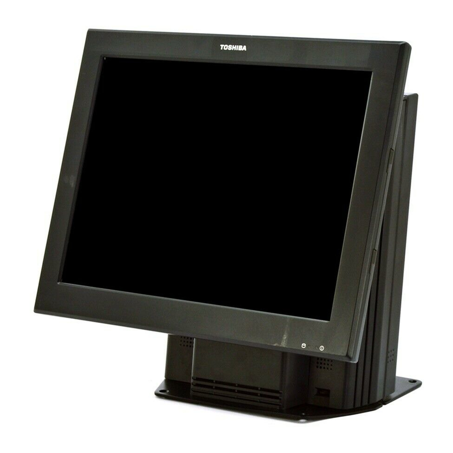
1. INTRODUCTION 1.1 Applicable Model 1. INTRODUCTION Thank you for choosing the TOSHIBA POS Terminal. This POS terminal contains all the high performance register functions necessary for a specialty/hospitality POS terminal and enables the user oriented system configuration. The operation panel can be chosen from 12-inch TFT display and 15-inch TFT display. -
Page 7: Appearance
2. APPEARANCE EO1-12037 2. 1 Standard Model 2. APPEARANCE 2.1 Standard Model 12-inch display POS terminal 15-inch display POS terminal... - Page 8 2. APPEARANCE EO1-12037 2. 1 Standard Model...
- Page 9 2. APPEARANCE EO1-12037 2.2 Available Options LED and CONTROL BUTTON DESCRIPTION This is the LED to indicate the power ON/OFF status of the POS terminal. The blue LED is Power LED (Blue) illuminated when the power is ON. The yellow LED is illuminated during the HDD LED (Yellow) access to the hard disk drive.
-
Page 10: Available Options
2. APPEARANCE EO1-12037 2.2 Available Options 2.2 Available Options Wireless Adaptor Case Fixed type customer display Magnetic Card Reader Tilt type customer display (MCR) iButton Remote type customer display... -
Page 11: Examples Of Pos Terminal With Some Options
2. APPEARANCE EO1-12037 2.3 Examples of POS Terminal with Some Options 2.3 Examples of POS Terminal with Some Options... -
Page 12: Connectors
2. APPEARANCE EO1-12037 2.4 Connectors 2.4 Connectors CAUTION! The drawer interface connector is exclusively for connecting the drawer. Do not connect a phone line or any other cables than the drawer cable to this connector. Doing so may cause a failure of the phone line and this terminal. - Page 13 2. APPEARANCE EO1-12037 2.4 Connectors Connector Description AC inlet A connector for the AC inlet PS/2 (Mouse, Keyboard) Mini-DIN 6- Connector for the PS/2 type mouse, Connector for the pin female type connector PS/2 type keyboard Connector for the USB (Universal Serial Bus) interface USB V2.0/1.1 and UHCI (Conforming to Universal Hub Controller Interface V2.0/1.1) USB: General 5V USB X 6...
-
Page 14: Installation Procedure
3. INSTALLATION PROCEDURE EO1-12037 3.1 Environment for Installation 3. INSTALLATION PROCEDURE WARNING! Care must be taken not to get your fingers caught between the LCD Frame and the POS terminal when bending the display downward. CAUTION! When removing the protective film from the display surface, please be sure to do it slowly. If it is done quickly, static electricity may generate, and the TFT may be damaged. -
Page 15: Connecting The Ac Plug
3. INSTALLATION PROCEDURE EO1-12037 3.2 Connecting the AC Plug 3.2 Connecting the AC Plug 1. Push on both sides of the molded Tower (TWR) Tail Cover to remove it from the system in order to gain access of the AC inlet. 2. -
Page 16: Adjustment
4. ADJUSTMENT EO1-12037 4.1 Tilt Angle Adjustment 4. ADJUSTMENT Tilt angle and brightness of the operator’s display can be adjusted. Adjustment method is common to both of 12-inch display model and 15-inch display model. CAUTION! 1. Do not adjust the display angle by holding the LCD panel. Doing so may damage the unit. Be sure to hold the LCD frame. -
Page 17: Brightness Adjustment
4. ADJUSTMENT EO1-12037 4.2 Brightness Adjustment 4.2 Brightness Adjustment The brightness control is provided on the lower right of the operator’s display. Turning it to the left makes the display darker, and turning it to the right makes the display brighter. -
Page 18: Volume Adjustment
EO1-12037 4. ADJUSTMENT 4.3 Volume Adjustment 4.3 Volume Adjustment The volume control is provided on the lower right of the tower. Turning it to the left makes the volume lower, and turning it to the right makes the volume higher. -
Page 19: Magnetic Card Reader (Option)
5. MAGNETIC CARD READER (OPTION) EO1-12037 5.1 How to Read Magnetic Card 5. MAGNETIC CARD READER (OPTION) The optional magnetic card reader can be installed. 5.1 How to Read Magnetic Card Insert the magnetic card into the upper portion of the magnetic card reader slot and slowly move the card downward. -
Page 20: Ibutton (Option)
6. iBUTTON® (OPTION) EO1-12037 6.1 How to Read iButton 6. iButton (OPTION) ® The optional iButton unit can be installed on the bottom of the LCD. 6.1 How to Read iButton CAUTION! 1. Keep storage media, like a floppy disk, away from the touch probe. The magnet of the touch probe may destroy the stored data Keep a metal object like a paper clip away from the touch probe. -
Page 21: General Maintenance
7. GENERAL MAINTENANCE EO1-12037 7. General Maintenance 7. GENERAL MAINTENANCE WARNING! 1. Be sure to disconnect the power cord prior to performing any maintenance. 2. Do not pour water directly on or wipe the operator’s display with a soaked cloth, as this may cause fire, electric shock, or machine failure. -
Page 22: Troubleshooting
8. TROUBLESHOOTING WARNING! If you cannot solve a problem with the following solutions, do not attempt to repair it by yourself. Turn the power off, unplug the POS Terminal, then contact the nearest TOSHIBA TEC service representative for assistance Symptom... -
Page 23: Specifications
9. SPECIFICATIONS EO1-12037 9.1 Basic Specifications 9. SPECIFICATIONS 9.1 Basic Specifications Description Item Intel Celeron M 440 (1.86GHz) 512 MB/1GB (max. 2GB) SO-DIMM DDR2-533/PC2-4200, 2 slots Memory 3.5" HDD SATA x max.1 (40 GB) 2.5” HDD SATA x max.2 (120 GB) Mutually available 3.5”... - Page 24 9. SPECIFICATIONS EO1-12037 9.2 Options 9.2 Options Option Model Description 24V-drive standard drawer Dimensions and Weight: DRWST-51A-4MVK-QM-R 460(W) x 400(D) x 115(H) mm / 18.1(W) x 15.7 (D) x 4.5(H) inch DRWST-51A-8MVK-QM-R 10 Kg / 22 lb Money Case Type: MC4, 8 Drawer unit Bill Coin...
- Page 25 English Waste Recycling information for users: Following information is only for EU-member states: The crossed out wheeled bin symbol is used to indicate that the product must not be treated as general household waste. By ensuring that this product is disposed of correctly you will be helping to prevent potentially negative consequences for the environment and human health, which could otherwise be caused by incorrect waste handling of this product.
- Page 26 EO1-12037...