HP 53131A Operating Manual
225 mhz universal counter
Hide thumbs
Also See for 53131A:
- Programming manual (330 pages) ,
- Assembly and service manual (254 pages)
Table of Contents
Quick Links
Table of Contents

Related Manuals for HP 53131A


Summary of Contents for HP 53131A
- Page 1 Operating Guide HP 53131A/132A 225 MHz Universal Counter...
- Page 3 Operating Guide This guide describes how to use the HP 53131A/132A 225 MHz Universal Counter. The information in this guide applies to instruments having the number prefix listed below, unless accompanied by a “Manual Updating Changes” package indicating otherwise. SERIAL PREFIX NUMBER:...
- Page 4 If HP receives notice from the mains power source to of such defects during the the product’s ground circuitry. warranty period, HP will, at its option, either repair or replace WARNING products which prove to be Indicates earth (ground) WHEN MEASURING POWER defective.
-
Page 5: Table Of Contents
Support xviii Accessories Supplied and Available Accessories Supplied Accessories Available Supplied Manuals Differences Between Prior and Current Revisions of the HP 53131A/132A HP 53131A Containing Firmware Revisions (3317, 3335, or 3402) Calibrations Measurements Statistics xxii HP-IB Commands xxii HP 53132A Time Interval Delay Arming... - Page 6 Contents HP 53131A/132A Quick Reference Guide xxiii Getting Started The Front Panel at a Glance The Front Panel Indicators at a Glance The Front Panel Indicators at a Glance (Cont.) The Front Panel Menus at a Glance The Front Panel Menus at a Glance (Cont.) The Front Panel Menus at a Glance (Cont.)
- Page 7 Contents Setting the Counter to Flag and Stop Measuring On Out-of-Limit Measurements 1-28 Setting the Counter to Flag On Limits But Continue Measuring 1-29 Disabling Limit Testing 1-30 Disabling Math 1-30 To Perform Statistics on Measurements 1-31 Selecting the Type of Statistics (Stats) 1-31 Computing Stats on Filtered Data Only 1-32...
- Page 8 EXTERNAL Arming 2-17 TIME Arming 2-17 DIGITS Arming 2-17 HP 53131A (and HP 53132A With S/N Prefix Below 3646) Time Interval DELAY Arming 2-17 HP 53132A (With S/N Prefix 3646 and Above) Time Interval DELAY Arming 2-20 To Use the Gate and External Arm...
- Page 9 Contents Example Procedure for Turning Off Math Mode 2-30 Example Procedure for Setting the Offset From the Last Measurement Value 2-31 Overview of Statistics (Stats) Menu 2-32 To Use the Stats Menu for Automatic and Continuous Statistical Analysis 2-33 Example Procedure for Computing Stats 2-33 Example Procedure for Easy Viewing of Stats 2-34...
- Page 10 To Select the Numerical Convention for the Display 2-65 To Connect the Counter to a Serial Printer via the RS-232 Port 2-65 To Connect the Counter to a Printer via HP-IB 2-66 To Select the HP-IB Talk-Only Mode for Printing 2-66 viii...
- Page 11 HP-IB Messages 2-77 Preset Values After Power-Up and *RST 2-78 HP 53131A (and HP 53132A With S/N Prefix Below 3646) Preset Values for Functions Accessible Via Front Panel or HP-IB 2-79 HP 53132A (With S/N Prefix 3646 and Above) Preset Values...
- Page 12 Contents Specifications Introduction Instrument Inputs Instrument Inputs (Continued) Time Base Measurement Specifications Measurement Specifications (Continued) Measurement Definitions 3-12 Measurement Definitions (Continued) 3-13 Measurement Arming and Processing 3-14 Measurement Arming and Processing (Continued) 3-15 General Information 3-16 Index Operating Guide...
- Page 13 In This Guide This book is the operating guide for the HP 53131A and HP 53132A 225 MHz Universal Counters. It consists of a table of contents, this preface, a quick reference guide, three chapters, and an index. This preface contains the following information: •...
-
Page 14: In This Guide
In This Guide Contents and Organization Table of Contents The Quick Reference Guide consists of a Menu Tree (cut-out sheet) that serves as a device to trigger your memory or get you quickly reacquainted with the instrument, and Menu Roadmaps that illustrate how to navigate through the menus. -
Page 15: Related Documents
Related Documents For more information on universal counters refer to the following Series 200 Application Notes: • Fundamentals of Electronic Frequency Counters Application Note 200—HP part number 02-5952-7506. • Fundamentals of Time Interval Measurements Application Note 200-3—HP part number 02-5952-7561. •... -
Page 16: Types Of Service Available If Your Instrument Fails
Fails If your HP 53131A/132A fails within three years of original purchase, HP will repair it free of charge. If your instrument fails after your 3-year warranty expires HP will repair it, or you can repair it yourself by ordering the service guide. -
Page 17: Repackaging For Shipment
HP 53131A/132A to the designated HP Service Center, using the shipping carton of the instrument. HP will notify you when your failed instrument has been received. If the instrument is to be shipped to HP for service or repair, be sure you do the following: •... -
Page 18: Description Of The 225 Mhz Universal Counter
Channel 3 Option 030, Option 050, or Option 124, this capability is extended to 3.0, 5.0, or 12.4 GHz, respectively. For the HP 53131A, frequency and time interval resolutions are 10 digits in one second and 500 picoseconds, respectively. The HP 53131A provides... - Page 19 Programmable control is performed via an HP-IB. The HP-IB and a talk-only RS-232C serial port are standard for the HP 53131A and HP 53132A. The serial port is for printing measured and analyzed data on serial printers, or for outputting an out-of-limit signal.
-
Page 20: Options
In This Guide Options The options available for the HP 53131A/132A 225 MHz Universal Counter are listed following this paragraph. Specifications for the options are listed in Chapter 3, “Specifications.” If you’ve purchased an option with the initial order, it will be installed at the factory and ready for operation at delivery. -
Page 21: Accessories Supplied And Available
Power cord, 2.3 meters Accessories Available • HP 34161A Accessory Pouch • HP 34131A Transit Case • Printer RS-232 Interface cables, HP 24542G or HP 24542H • HP-IB cables, HP 10833A/B/C/D Supplied Manuals • HP 53131A/132A Operating Guide—this guide (HP P/N 53131-90055) •... -
Page 22: Differences Between Prior And Current Revisions Of The Hp 53131A/132A
Differences Between Prior and Current Revisions of the HP 53131A/132A If you have an HP 53131A containing one of the prior firmware revisions (3317, 3335, or 3402), read the subsection below titled “HP 53131A Containing Firmware Revisions (3317, 3335, or 3402)” to get an overview of the differences between the earlier firmware revisions and current firmware revision. -
Page 23: Calibrations
A more accurate Time Interval calibration (FINE TI) is not available. See the section titled “Using the Calibration Menu” in Chapter 2 of the HP 53131A/132A Operating Guide for details. Measurements If your Counter contains other than the current firmware revision, the following measurement capabilities are different: •... -
Page 24: Statistics
50% level. HP 53132A Time Interval Delay Arming HP 53131A and HP 53132A Counters with a serial number prefix below 3646 are identical in their TI arming modes. Both only offer Time Interval Delay, where the STOP trigger of a time interval measurement can be delayed by a user-specified time. -
Page 25: Hp 53131A/132A Quick Reference Guide
HP 53131A/132A Quick Reference Guide The Quick Reference Guide is designed for experienced users of the HP 53131A/132A Universal Counter. It is intended to be used as a tool to trigger your memory. If you are using the HP 53131A/132A for the first time, HP recommends that you at least read Chapter 1, “Getting Started,”... - Page 26 xxiv Operating Guide...
- Page 27 SHOW: MEAN ON FAIL: STOP MATH: OFF SHOW: MATH: SHOW: SHOW: NUMBER MATH HELP? SHOW: GRAPH STATS: OFF STATS: USE: ALL MEAS USE: I N L I M I T ON SINGLE: 1 ON SINGLE: (HP 53131A and HP 53132A)
- Page 28 COMMON 1: COMMON 1: 100kHz Attenuate Filter CH 1: 50 OHM CH 1: DC CH 1: X10 ATT CH 1: LP FILT CH 1: 1M OHM CH 1: CH 1: X1 ATT CH 1: NO FILT (HP 53131A and HP 53132A)
- Page 29 TIME: .100 s Gate & ExtArm ARM : EXTERNL ARM: AUTO DELAY : NONE DELAY : TIME SLOPE : POS SLOPE : T IME : .01000 DELAY: NONE DELAY: TIME TIME : .01000 (HP 53131A and HP 53132A S/N below 3646)
- Page 30 DELAY : NONE DELAY :TIME SLOPE : POS DELAY: NONE DELAY: TIME DELAY: EVENT STOP : AUTO STOP : EXT SLOPE : SLOPE : POS DELAY : NONE DELAY : TIME DELAY : EVENT (HP 53132A S/N 3646 and above)
- Page 31 Time & Other RATIO 1 TO 3 POS WIDTH 1 VOLT PEAKS 2 Ratio Period Meas Time & Freq & NEG WIDTH 1 RATIO 2 TO 1 Ratio Period Freq & RATIO 3 TO 1 Ratio (HP 53131A and HP 53132A)
- Page 32 GATE: EXTERNL START: Gate & STOP: ExtArm STOP: AUTO STOP: Gate & ExtArm STOP: STOP: TIME Gate & TIME: .100 ExtArm Enter TIME: .2000 Gate & Gate & GATE: DIGITS DIGITS: ExtArm ExtArm Enter DIGITS: (HP 53131A and HP 53132A)
- Page 33 Gate & ARM: ARM: AUTO ExtArm ARM: EXTERNL Gate & SLOPE: ExtArm SLOPE: SLOPE: Gate & DELAY: ExtArm DELAY: NONE DELAY: T I M E Gate & TIME: .01000 ExtArm Enter TIME: .02000 (HP 53131A and HP 53132A S/N below 3646)
- Page 34 Period START: START: Gate & ExtArm START: AUTO SLOPE: Gate & ExtArm SLOPE: SLOPE: Gate & DELAY: ExtArm DELAY :NONE DELAY :TIME DELAY :EVENT Gate & ExtArm Enter 100.1 Gate & ExtArm Enter 1000 (HP 53132A S/N 3646 and above)
- Page 35 STOP :EXT STOP :AUTO SLOPE : Gate & ExtArm SLOPE : SLOPE : Gate & DELAY : ExtArm DELAY :NONE DELAY :TIME DELAY :EVENT Gate & ExtArm Enter 100.1 Gate & ExtArm Enter 1000 (HP 53132A S/N 3646 and above)
- Page 36 Uppr & LOWR: 0.000000 LOWR: 4.900000 Lower Limit Modes Limit LIM TEST: LIM TEST: Modes LIM TEST: Limit ON FAIL:GO ON FAIL:GO ON Modes ON FAIL: STOP Limit SHOW: NUMBER SHOW: NUMBER Modes SHOW: GRAPH (HP 53131A and HP 53132A)
- Page 37 Enter Scale & OFFS: 0.000000 OFFS: 0.500000 Offset Enter Scale & SET OFFSET? OFFS:-nnnnnnn Offset Scale & MATH: MATH: Offset MATH: Enter Scale & MATH HELP ? (MEAS X SCALE) + OFFS = RESULT Offset (HP 53131A and HP 53132A)
- Page 38 Stats MATH Stats Stats Stats SHOW: Enter SHOW: MEAS SHOW: STD DEV SHOW: MEAN Stats STATS: SHOW: SHOW: STATS: STATS: Stats USE: USE: ALL MEAS USE: IN LIMIT Stats ON SINGLE: ON SINGLE: ON SINGLE: (HP 53131A and HP 53132A)
- Page 39 LEVEL: 75 PCT FALLTIME 1 POS WIDTH 1 Enter NEG WIDTH 1 Trigger SLOPE: Sensitivity Other Meas SLOPE: SLOPE: TOTALIZE PHASE 1 TO 2 Trigger SENSTVTY: DUTY CYCLE 1 Sensitivity SENSTVTY: Trigger Sensitivity SENSTVTY: SENSTVTY: (HP 53131A and HP 53132A)
- Page 40 AUTO TRG: Trigger LEVEL: 0.000V LEVEL: 2.000V Sensitivity Enter Trigger LEVEL: 50 PCT LEVEL: 75 PCT Sensitivity Trigger SLOPE: SLOPE: Sensitivity SLOPE: Trigger SENSTVTY: SENSTVTY: Sensitivity SENSTVTY: SENSTVTY: Trigger COMMON 1: COMMON 1: Sensitivity COMMON 1: (HP 53131A and HP 53132A)
-
Page 41: Getting Started
Getting Started... -
Page 42: The Front Panel At A Glance
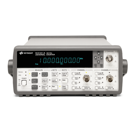
Chapter 1 Getting Started The Front Panel at a Glance The Front Panel at a Glance CHANNEL 3 5 3131 A 225 MHz 100 MHz 3 GHz UNIVERSAL COUNTER µs + / – Enter Gate Damage Lvl: Period Freq +Wid -Wid Rise Fall Time Ch 1 Ch 2 Ch 3 Limit ExtRef... -
Page 43: The Front Panel Indicators At A Glance
Chapter 1 Getting Started The Front Panel Indicators at a Glance The Front Panel Indicators at a Glance There are eight different groups of indicators or LEDs. They are listed and described in the following table. Indicators Description of the Indicators When one of these indicators is lit, it simultaneously Freq &... -
Page 44: The Front Panel Indicators At A Glance (Cont.)
Chapter 1 Getting Started The Front Panel Indicators at a Glance (Cont.) The Front Panel Indicators at a Glance (Cont.) Indicators Description of the Indicators When this indicator flashes, it indicates that the Counter is triggering on the input signal. If the input signal is too high, this indicator remains ON. -
Page 45: The Front Panel Menus At A Glance
Chapter 1 Getting Started The Front Panel Menus at a Glance The Front Panel Menus at a Glance Freq & Time & Other Gate & Ratio Period Meas ExtArm FREQUENCY 1 T I 1 TO 2 T O T A L I Z E 1 GATE: TIME FREQUENCY 2 PERIOD 1... -
Page 46: The Front Panel Menus At A Glance (Cont.)
Chapter 1 Getting Started The Front Panel Menus at a Glance (Cont.) The Front Panel Menus at a Glance (Cont.) Recall Save & Trigger Print Sensitivity NO REGISTERS SAVE: AUTO TRG: ON AUTO TRG: RECALL 0 UNSAVE: LEVEL: 50 PCT LEVEL: 0.000V RECALL 1... - Page 47 The Front Panel Menus at a Glance (Cont.) NOTE Turn power off, press and hold Recall (Utility) key, then press POWER key to access this menu. POWER Utility Recall On / Stby REV: TEST: ALL? HP-IB: BAUD: 9600 TEST: DISP? TIMEBAS: AUTO BAUD: 19200 TEST: CPU? TIMEBAS:...
-
Page 48: The Front Panel Menus At A Glance (Cont.)
Chapter 1 Getting Started The Front Panel Menus at a Glance (Cont.) The Front Panel Menus at a Glance (Cont.) NOTE Turn power off, press and hold Scale & Offset key, then press POWER key to access this menu. (This menu does not exist in early versions of the Counter. -
Page 49: The Display Annunciators At A Glance
Chapter 1 Getting Started The Display Annunciators at a Glance The Display Annunciators at a Glance µs Gate Period Freq +Wid -Wid Rise Fall Time Ch 1 Ch 2 Ch 3 Limit ExtRef Annunciator Indication Period Counter is set to measure Period. Freq Counter is set to measure Frequency. -
Page 50: The Display Special Character At A Glance
Chapter 1 Getting Started The Display Special Character at a Glance The Display Special Character at a Glance µs Gate Period Freq +Wid -Wid Rise Fall Time Ch 1 Ch 2 Ch 3 Limit ExtRef Special Character Description A placeholder that indicates this digit is not significant. -
Page 51: The Rear Panel At A Glance
WARNING: FOR CONTINUED FIRE PROTECTION, USE SPECIFIED ~ LINE FUSE. 1 Rear-panel input connectors 6 10 MHz Output connector (optional) 7 HP-IB (IEEE-488.1) 2 Power module (Senses incoming interface connector voltage and automatically 8 Oscillator Adjust potentiometer selects proper setup.) -
Page 52: Making Measurements
Making Measurements Making Measurements One of the first things you will want to do with your HP 53131A/132A Universal Counter is to become acquainted with its front panel. Therefore, we have written the procedures in this section to familiarize you with some of its controls. -
Page 53: To Measure Frequency
Chapter 1 Getting Started Making Measurements Legend 1 Press key one time 4 Press and hold 8 Disconnect signal and release 5 Result 9 Indicator off 2 Press key two times 6 Auto operation 10 Indicator on and release 7 Connect signal 11 Indicator flashing 3 Repeated key presses To Measure Frequency... - Page 54 Chapter 1 Getting Started Making Measurements Earlier versions of the Counter do not momentarily display the HP-IB NOTE address at turn-on. Connect (for demonstration purposes) the Counter’s rear-panel 10 MHz Out signal to CHANNEL 1 input as shown in the illustrated procedure, below.
-
Page 55: To Select Input Coupling And Impedance
Chapter 1 Getting Started Making Measurements Again, the Counter will automatically display the measured frequency of the input signal. If you need or want to change CHANNEL 2’s coupling, impedance, and triggering conditions to match the input signal you are trying to measure, the next procedures “To Select Input Coupling and Impedance”... -
Page 56: Selecting Input Impedance
Chapter 1 Getting Started Making Measurements Selecting Input Impedance Channel 2’s input impedance is now set to 50 . NOTE The “arrow” keys can also be used to toggle the state of toggle keys (DC/AC, 50 /1M , etc.) as indicated by the flashing indicator within the arrow keys. -
Page 57: To Set Input Channel Trigger Level/Sensitivity
Chapter 1 Getting Started Making Measurements To Set Input Channel Trigger Level/Sensitivity Changing Trigger Mode Trigger Sensitivity Press any one of these arrow keys to toggle to the next state of Auto Trigger. + / – Enter Modifying Input Trigger Level Trigger Sensitivity The leftmost “0”... -
Page 58: Selecting Input Trigger Slope
Chapter 1 Getting Started Making Measurements To set the trigger level to 0.05V, perform the following steps. + / – Enter NOTE BE SURE to always press the Enter key to complete numeric data entries. Channel 2’s trigger level is now set to 0.05V. Selecting Input Trigger Slope Trigger Sensitivity... -
Page 59: Selecting Input Sensitivity
Chapter 1 Getting Started Making Measurements Selecting Input Sensitivity Trigger Sensitivity Display 1, 7/13/92 Display 1, 7/13/92 Display 1, 7/13/92 Starting the Measurement Gate Freq Ch 2 The Run key initiates repetitive measurements, and is described in the section titled “To Control Measurement” at the end of this chapter. To Select Scale and Offset The Scale &... -
Page 60: Entering The Scale Value
Chapter 1 Getting Started Making Measurements Entering the Scale Value MATH Scale & Offset Scale & Offset Stats To demonstrate the Scale Math operation, set Scale to 10 as shown in the following steps. Press and hold the key until the value of Scale is 10 as shown in the following step. -
Page 61: Entering The Offset Value
Chapter 1 Getting Started Making Measurements Entering the Offset Value To demonstrate the Offset Math operation, set the Offset to 1 MHz as shown in the following steps. Scale & Offset At this point, pressing the key will cause the Counter to display the full display of the Offset value as shown in the following step. -
Page 62: Displaying The Math Results
Chapter 1 Getting Started Making Measurements Displaying the Math Results Freq Ch 2 The Counter displays the modified measurement results, which are based on the scale and offset values that you selected in the previous steps. That is, the 101 represents the original 10, scale multiplied by 10, then offset by 1. -
Page 63: To Set Limits Of Measurements
Chapter 1 Getting Started Making Measurements To Set Limits of Measurements To demonstrate how Math and Limits work together, use the Scale (10) and Offset (1 Mega) values selected in the previous procedure “To Select Scale and Offset.” Enable Math by performing the following steps. Scale &... -
Page 64: Setting The Upper Limit
Chapter 1 Getting Started Making Measurements Setting the Upper Limit LIMITS Uppr & Lower Uppr & Lower Limit Modes Press the key six more times to cause the Counter to display your entry in Mega units as shown in the following step. The leftmost “0”... - Page 65 Chapter 1 Getting Started Making Measurements Enter NOTE BE SURE to press the Enter key to enter the 102 Mega value. 1 102 Mega Upper Limit 2 101 Mega Scale/Offset Measurement Figure 1-1. 102 Mega Upper Limit Setting Operating Guide 1-25...
-
Page 66: Setting The Lower Limit
Chapter 1 Getting Started Making Measurements Setting the Lower Limit Uppr & Lower Press the arrow keys as shown in the following steps to set the lower limit value. Press the key six more times to cause the Counter to display your entry in Mega units as shown in the following step. -
Page 67: Operating Guide
Chapter 1 Getting Started Making Measurements Limits should now be set as shown in Figure 1-2. 1 102 Mega Upper Limit 2 101 Mega Scale/Offset Measurement 3 100 Mega Lower Limit Figure 1-2. 100 Mega Lower and 102 Mega Upper Limits Settings Figure 1-3 represents what transpired during this Math and Limits procedure. -
Page 68: Setting The Counter To Flag And Stop Measuring On Out-Of-Limit Measurements
Chapter 1 Getting Started Making Measurements Setting the Counter to Flag and Stop Measuring On Out-of-Limit Measurements If you want the Counter to stop measuring when the signal exceeds the limits (102 to 100 Mega) that you entered in the previous procedure, perform the following steps to select the STOP choice in the ON FAIL display. -
Page 69: Setting The Counter To Flag On Limits But Continue Measuring
Chapter 1 Getting Started Making Measurements Setting the Counter to Flag On Limits But Continue Measuring Perform the following steps to select the GO ON choice in the ON FAIL display if you want the Counter to continue measuring even though an measurement result exceeds the limits previously entered. -
Page 70: Disabling Limit Testing
Chapter 1 Getting Started Making Measurements Disabling Limit Testing Limit Modes The Counter is now making measurements without limit testing. Disabling Math Scale & Offset Display 1, 7/13/92 Display 1, 7/13/92 Gate Freq Ch 2 The Counter is now making measurements without the scale/offset values calculated into the measurements. -
Page 71: To Perform Statistics On Measurements
Chapter 1 Getting Started Making Measurements To Perform Statistics on Measurements Selecting the Type of Statistics (Stats) Suppose you want the Counter to compute and display the standard deviation of the current input data (which is the 10 MHz signal applied to CHANNEL 2). -
Page 72: Computing Stats On Filtered Data Only
Chapter 1 Getting Started Making Measurements The Counter is now set to make statistics based on 20 measurements. Freq Ch 2 Gate Freq Ch 2 Gate Freq Ch 2 In this case, the displayed standard deviation value is computed on all measurements of the 10 MHz signal since no limits were set. - Page 73 Chapter 1 Getting Started Making Measurements Perform the following steps to select the IN LIMIT choice in the USE display if you want the Counter to compute statistics on only frequency measurements within the limits you set. Stats Display 1, 7/13/92 Display 1, 7/13/92 Since the Limits were set to 101 Mega and 102 Mega values that are based on a scale of 10 and offset of 1 Mega, you must re-enable Math now...
-
Page 74: Displaying Stats After Filtering Data Of Input Signal
Chapter 1 Getting Started Making Measurements Displaying Stats After Filtering Data of Input Signal Let’s assume you have set the upper and lower limits for the input signal, and selected the IN LIMIT (filtering) choice. Now, perform the following steps to display the standard deviation of the filtered measurements. (Note that the first step in the following procedure is optional since you should have already set Stats to show standard deviation at the beginning of this Stats procedure. -
Page 75: Disabling Stats And Math
Chapter 1 Getting Started Making Measurements Disabling Stats and Math Stats Scale & Offset Display 1, 7/13/92 Display 1, 7/13/92 Gate Freq Ch 2 The Counter is now making and displaying normal measurements (that is, the Counter is not showing statistics or scale/offset results). Operating Guide 1-35... -
Page 76: To Control Measurement
Chapter 1 Getting Started Making Measurements To Control Measurement Use these two keys to control the measurement of the Counter. The Run key provides repetitive measurements, whereas the Single/ Stop Stop/Single key allows you to make one measurement. With the 10 MHz signal still connected to CHANNEL 2, perform the following steps so you can better understand the Run and Stop/Single operations. -
Page 77: Operating Your Universal Counter
Operating Your Universal Counter Operator’s Reference... -
Page 78: Introduction
Introduction Introduction This is the operator’s reference chapter which contains information and procedures for the front-panel keys, operating functions, and menus of the HP 53131A/132A 225 MHz Universal Counter. Chapter Summary • How this Counter Works for You page 2-4 •... -
Page 79: Where To Find Some Key Working Examples
Chapter 2 Operating Your Universal Counter Introduction Where to Find Some Key Working Examples • Example Procedure for Gate and External Arm page 2-24 • Example Procedure for Changing the Number of page 2-25 Digits of Resolution Displayed for More Precise Measurements •... -
Page 80: How This Counter Works For You
Cycling the POWER key presets the Counter. • The Counter’s Utility menu allows you to select such things as timebase source, HP-IB configuration, and RS-232 serial port configuration. After your selections, the Counter automatically stores all these selections in non-volatile memory (except the timebase source);... -
Page 81: Using The Measurement Control Keys (Run And Stop/Single)
(Run and Stop/Single) Overview of the Measurement Control Keys Stop/ Two measurement control keys are provided on the HP 53131A/132A Single Counter: Run and Stop/Single. In general, the Run key provides repetitive measurements while the Stop/Single key allows you to make single-shot measurements. -
Page 82: To Use The Measurement Control Keys
Chapter 2 Operating Your Universal Counter Using the Measurement Control Keys (Run and Stop/Single) To Use the Measurement Control Keys The following procedure demonstrates how these keys function. Connect power source to Counter, and turn on Counter. All segments of the front-panel display will light up while the Counter performs its power-on self-test, and then dashes are displayed. - Page 83 Chapter 2 Operating Your Universal Counter Using the Measurement Control Keys (Run and Stop/Single) Press Stop/Single key. One set of N frequency measurements is taken with each press of the Stop/Single key. One set of statistics is computed with each press of the Stop/Single key.
-
Page 84: Using Entry/Select (Arrow) Keys
Chapter 2 Operating Your Universal Counter Using Entry/Select (Arrow) Keys Using Entry/Select (Arrow) Keys There are six entry/select keys of which four are “arrow” keys. The function of the four arrow keys and the Enter key depends on the Counter’s operating mode (that is, numeric entry, state changing, sequencing through choices in a menu, etc.). -
Page 85: To Use During State Changing (On/Off, Lo/Med/Hi, Etc.)
Chapter 2 Operating Your Universal Counter Using Entry/Select (Arrow) Keys To Use During State Changing (ON/OFF, LO/MED/HI, etc.) • Press any of the arrow keys to toggle or change to the next state of the parameters found in the following menus: –... -
Page 86: Using The Measure Menu Keys
Meas ExtArm • Time interval, period, and pulse characterization measurements. (The HP 53131A/132A provides one key-press operation for such pulse measurements as risetime, falltime, pulse width, etc., which have traditionally required multiple key presses or operations.) • Other measurements (dutycycle, phase, peak voltage, and totalize). -
Page 87: To Measure Frequency
Chapter 2 Operating Your Universal Counter Using the MEASURE Menu Keys To Measure Frequency Connect power source to Counter, and turn on Counter. All segments of the front-panel display will light up while the Counter performs its power-on self-test, and then dashes are displayed. The Counter is now ready to measure frequency of a signal applied to CHANNEL 1 input. -
Page 88: To Measure Frequency Ratio
Chapter 2 Operating Your Universal Counter Using the MEASURE Menu Keys To Measure Frequency Ratio Press Freq & Ratio key until RATIO 1 TO 2 is displayed. RATIO 1 TO 2 is momentarily displayed, the Freq, Ch1, and Ch2 annunciators light, and the Counter is ready to measure and display the frequency ratio of a signal applied to CHANNEL 1 in relation to a signal applied to CHANNEL 2 (Ch1/Ch2). -
Page 89: To Measure Time Interval
Chapter 2 Operating Your Universal Counter Using the MEASURE Menu Keys To Measure Time Interval Press Time & Period key until TI 1 TO 2 is displayed. TI 1 TO 2 is momentarily displayed, the Time, Ch1, and Ch2 annunciators light, and the Counter is ready to measure the length of time between a start event on CHANNEL 1 and a stop event on CHANNEL 2. -
Page 90: To Measure Positive/Negative Pulse Widths
Chapter 2 Operating Your Universal Counter Using the MEASURE Menu Keys To Measure Positive/Negative Pulse Widths Press Time & Period key until POS WIDTH 1 or NEG WIDTH 1 , depending on which measurement you want to make, is displayed. POS WIDTH 1 or NEG WIDTH 1 is momentarily displayed, and the +Wid or Wid, and Ch1 annunicators light. -
Page 91: To Make Phase Measurements
Chapter 2 Operating Your Universal Counter Using the MEASURE Menu Keys To Make Phase Measurements Press Other Meas key until PHASE 1 TO 2 is displayed. PHASE 1 TO 2 is momentarily displayed, the Ch1 and Ch2 annunicators light, and the Counter is ready to measure the phase of a signal applied to CHANNEL 1 input relative to a signal applied to CHANNEL 2 input. -
Page 92: Using The Gate & External Arm Menu Key
Using the Gate & External Arm Menu Key Overview of Gate/External Arming Functions Table 2-2 for the HP 53131A (and HP 53132A with a serial number prefix MEASURE below 3646) and Table 2-3 for the HP 53132A with a serial number prefix Freq &... -
Page 93: External Arming
Digits arming is demonstrated in the sub-section titled “Example Procedure for Changing the Number of Digits of Resolution Displayed for More Precise Measurements.” HP 53131A (and HP 53132A With S/N Prefix Below 3646) Time Interval DELAY Arming The DELAY capability (specified in the Time Interval arming menu) provides a variable delay between the start event (Channel 1) and the enabling of the stop event (Channel 2) as shown Figure 2-1. - Page 94 ACTUAL T.I. MEAS DELAY TIME ARM: EXTERNL, SLOPE: POS, DELAY: TIME, TIME: (specified) Figure 2-1. HP 53131A (HP 53132A S/N Prefix Below 3646) Time Interval Delay NOTE The examples in Figure 2-1 have the input signal applied to Channel 1 with COMMON 1: ON, Channel 1 SLOPE: POS, and Channel 2 SLOPE: POS.
- Page 95 Chapter 2 Operating Your Universal Counter Using the Gate & External Arm Menu Key Table 2-2. HP 53131A (HP 53132A S/N Prefix Below 3646) Gate & External Arm Key Menus as a Function of the Measurement and Arming Mode Freq, Period,...
-
Page 96: Hp 53132A (With S/N Prefix 3646 And Above) Time Interval Delay Arming
Chapter 2 Operating Your Universal Counter Using the Gate & External Arm Menu Key HP 53132A (With S/N Prefix 3646 and Above) Time Interval DELAY Arming In the following subsections, a leading star ( ) means the parameter affects the START event. A trailing star means the parameter affects STOP event. - Page 97 ACTUAL T.I. MEAS DELAY STOP TO 4th EVENT START: AUTO, DELAY : EVENT, E : 4 Figure 2-2. HP 53132A (With S/N Prefix 3646 and Above) Auto Arming NOTE The examples in Figure 2-2 have the input signal applied to Channel 1 with COMMON 1: ON, Channel 1 SLOPE: POS, and Channel 2 SLOPE: POS.
- Page 98 SLOPE: POS, DELAY: EVENT, E: 5, STOP : EXT, SLOPE : NEG, DELAY : NONE Figure 2-3. HP 53132A (With S/N Prefix 3646 and Above) External Arming NOTE The examples in Figure 2-3 have the input signal applied to Channel 1 with COMMON 1: ON, Channel 1 SLOPE: POS, and Channel 2 SLOPE: NEG.
- Page 99 Chapter 2 Operating Your Universal Counter Using the Gate & External Arm Menu Key Table 2-3. HP 53132A (S/N Prefix 3646 and Above) Gate & External Arm Key Menus as a Function of the Measurement and Arming Mode Freq, Period,...
-
Page 100: To Use The Gate And External Arm
Chapter 2 Operating Your Universal Counter Using the Gate & External Arm Menu Key To Use the Gate and External Arm Example Procedure for Gate and External Arm For demonstration purposes, you want to set up the Counter so that it uses an external arm to start a measurement. -
Page 101: Example Procedure For Changing The Number Of Digits Of Resolution Displayed For More Precise Measurements
Chapter 2 Operating Your Universal Counter Using the Gate & External Arm Menu Key Press Gate & ExtArm key. STOP: NEG is displayed. Press any one of the arrow keys until STOP: TIME is displayed. Set the Gate Time to 5 ms by performing the following steps: a. - Page 102 Chapter 2 Operating Your Universal Counter Using the Gate & External Arm Menu Key To demonstrate how to use “digits arming” to change the number of digits displayed, perform the following steps first. a. Press Gate & ExtArm key GATE: TIME is displayed. b.
-
Page 103: Using The Math Menu Keys
Chapter 2 Operating Your Universal Counter Using the MATH Menu Keys Using the MATH Menu Keys Note that Math and Limits are not available for Totalize and Voltage MATH Peaks measurements. Scale & Offset Overview of Scale/Offset Math Menu Stats The Scale and Offset functions within the Math menu allow you to perform simple mathematical operations on the measurement result before it is displayed. -
Page 104: To Use The Scale/Offset Math Menu
Chapter 2 Operating Your Universal Counter Using the MATH Menu Keys To Use the Scale/Offset Math Menu Example Procedure for Scale Function For demonstration purposes, you have a motor that has a tachometer attached to its rotating shaft that generates a pulse for every revolution of the shaft. -
Page 105: Example Procedure For Offset Function
Chapter 2 Operating Your Universal Counter Using the MATH Menu Keys Press Scale & Offset key until OFFS: is displayed. OFFS: 0.000000 should be displayed. If the Offset value is not set to “0.000000”: a. Press the appropriate arrow keys to set the Offset to “0.000000.” b. -
Page 106: Example Procedure For Turning Off Math Mode
Chapter 2 Operating Your Universal Counter Using the MATH Menu Keys Press Scale & Offset key until OFFS: is displayed. OFFS: 0.000000 seconds should be displayed. This is the default value. Set the Offset to .1000000 s. Refer to the sub-section titled “Entering the Offset Value” in Chapter 1, “Getting Started,”... -
Page 107: Example Procedure For Setting The Offset From The Last Measurement Value
Chapter 2 Operating Your Universal Counter Using the MATH Menu Keys Example Procedure for Setting the Offset From the Last Measurement Value The SET OFFSET ? menu item uses the negative of the last measurement value, rounded to eleven digits, to set the OFFSET. Thus, any difference in the offset (or now the reference value) and the current measurement value is displayed. -
Page 108: Overview Of Statistics (Stats) Menu
Chapter 2 Operating Your Universal Counter Using the MATH Menu Keys Press Run key. is displayed, for example, at the completion of the next measurement. This value ( 0.00012) is the small difference between the signal being measured and the reference value ( OFFS: 10.00000 MHz ) obtained in step 5. -
Page 109: To Use The Stats Menu For Automatic And Continuous Statistical Analysis
Chapter 2 Operating Your Universal Counter Using the MATH Menu Keys To Use the Stats Menu for Automatic and Continuous Statistical Analysis Example Procedure for Computing Stats For demonstration purposes, let’s say you need to know the mean (average) and minimum risetime values of a digital signal. Also, you want the Counter to make 20 measurements before it performs these statistical computations. -
Page 110: Example Procedure For Easy Viewing Of Stats
Chapter 2 Operating Your Universal Counter Using the MATH Menu Keys Press Run key. Immediately after the Run key is pressed, the Counter momentarily displays DOING STATS . When the Counter has made 20 valid measurements, it then displays the mean risetime value of the digital input signal. -
Page 111: Example Procedure For Filtering Data (Using Limits) During Stats
Chapter 2 Operating Your Universal Counter Using the MATH Menu Keys Example Procedure for Filtering Data (Using Limits) During Stats Using the procedure in the previous sub-section titled “Example Procedure for Easy Viewing of Stats,” set up the Counter to display the minimum risetime value of an input signal. -
Page 112: Example Procedure For Configuring Single To Initiate N Measurements
Chapter 2 Operating Your Universal Counter Using the MATH Menu Keys Example Procedure for Configuring SINGLE to Initiate N Measurements Please refer to the procedure titled “To Use the Measurement Control Keys” on page 2-6 for an example use of ON SINGLE. Example Procedure for Turning Off Stats Mode Press Stats key until STATS: ON is displayed. -
Page 113: Using The Limits Menu Keys
Chapter 2 Operating Your Universal Counter Using the LIMITS Menu Keys Using the LIMITS Menu Keys Note that Math and Limis menus are not available for Totalize and Voltage Peaks measurements. Overview of Limits Menus LIMITS The menu items under the Limits keys allow you to: Uppr &... -
Page 114: To Set And Use Automatic Limit Testing
Chapter 2 Operating Your Universal Counter Using the LIMITS Menu Keys To Set and Use Automatic Limit Testing Limits Testing Example 1—Flag and Stop Measuring On Limits For demonstration purposes, you want to first measure the ratio between signals applied to channels 1 and 2 of the Counter. Next, you want to set limits that would cause the Counter to flag (turn on the Limits annunciator in the front-panel display) and stop making measurements if these signals drift more than ±10% apart. - Page 115 Chapter 2 Operating Your Universal Counter Using the LIMITS Menu Keys Press Limit Modes key until LIM TEST: ON is displayed. Note that once either the upper or lower limits have been set, the limit testing is automatically enabled as indicated by the LIM TEST: ON display, and the Limit Modes indicator.
-
Page 116: Limits Testing Example 2-Flag On Limits But Continue Measuring
Chapter 2 Operating Your Universal Counter Using the LIMITS Menu Keys Limits Testing Example 2—Flag On Limits but Continue Measuring If you decide that you want the Counter to flag measurements that are out of limits but to continue taking measurements, then perform the following steps. - Page 117 Chapter 2 Operating Your Universal Counter Using the LIMITS Menu Keys Press Run key to display the graph as shown below. Freq Ch 1 The asterisk (*) or star represents the measurement and the colons (:) represent the limits you set. This graph indicates that the measurement is within the limits.
-
Page 118: Limits Testing Example 4-Selecting Filtering Conditions Of Stats Computation
Chapter 2 Operating Your Universal Counter Using the LIMITS Menu Keys Limits Testing Example 4—Selecting Filtering Conditions of Stats Computation Let’s assume you have set the upper and lower limits to reasonable values as in the previous procedure. NOTE Since the Limit Testing and Stats functions are independent, LIM TEST: doesn’t have to be ON in order to filter measurements for statistics. -
Page 119: Limits Testing Example 5-Sending The Limit-Detect Output To The Rs-232 Serial Port
Chapter 2 Operating Your Universal Counter Using the LIMITS Menu Keys Limits Testing Example 5—Sending the Limit-Detect Output to the RS-232 Serial Port NOTE If you cycle power, you will lose everything except saved measurement setups and special parameters saved to non-volatile memory; therefore, make sure you use the Save and Recall functions of the Counter to retain the measurement setup prior to powering down to set up the the Limit-Detect Output line (pin 4) of the RS-232 serial connector. -
Page 120: Using Channel 1 And Channel 2 Input Conditioning Keys
Chapter 2 Operating Your Universal Counter Using CHANNEL 1 and CHANNEL 2 Input Conditioning Keys Using CHANNEL 1 and CHANNEL 2 Input Conditioning Keys The Trigger/Sensitivity keys are menu keys, while the other keys in this CHANNEL 1 Trigger group (that is, 50 /1 M , DC/AC, X10 Attenuate, and 100 kHz Filter) Sensitivity are toggle keys. - Page 121 Chapter 2 Operating Your Universal Counter Using CHANNEL 1 and CHANNEL 2 Input Conditioning Keys While AUTO TRIG: is ON, the Counter will, for each measurement, check that the measurement signal(s) are triggering at the current level(s). If no triggering is found, the Counter will measure and compute new trigger level(s).
- Page 122 Chapter 2 Operating Your Universal Counter Using CHANNEL 1 and CHANNEL 2 Input Conditioning Keys DEFINITION OF SENSITIVITY. Sensitivity is the lowest amplitude signal at a particular frequency that the Counter will count. The amplifier gain and the voltage difference between the input trigger hysteresis levels determine the Counter’s sensitivity.
- Page 123 Chapter 2 Operating Your Universal Counter Using CHANNEL 1 and CHANNEL 2 Input Conditioning Keys Upper Hysteresis Level Peak-to-Peak Trigger Sensitivity Level Lower Hysteresis Input signal Level to Counter Signal will not generate a count because the trigger level is set below the midpoint of the signal, causing the lower hysteresis level to not be crossed.
-
Page 124: To Use The Trigger/Sensitivity Keys To Adjust Counter's Triggering Level
Chapter 2 Operating Your Universal Counter Using CHANNEL 1 and CHANNEL 2 Input Conditioning Keys To Use the Trigger/Sensitivity Keys to Adjust Counter’s Triggering Level Example Procedure for Setting Trigger Voltage and Sensitivity Levels Connect a signal to channel 1 input, and set up the Counter to measure the frequency of the signal. - Page 125 Chapter 2 Operating Your Universal Counter Using CHANNEL 1 and CHANNEL 2 Input Conditioning Keys Press Trigger/Sensitivity key. SLOPE: POS is displayed. The trigger slope is set at positive; thus, the Counter triggers on the rising edge of the input signal as shown in the following figure.
-
Page 126: Operating Guide
Chapter 2 Operating Your Universal Counter Using CHANNEL 1 and CHANNEL 2 Input Conditioning Keys Press any one of the arrow keys until SENSTVTY: HI is displayed. The Counter’s CHANNEL 1 sensitivity is set high as shown in the following figure. Trigger Band The Counter should now be triggering as determined by the sensitivity... -
Page 127: Example Procedure For Using Common 1 To Make Time Interval (Ti) Measurements On A Single Signal
Chapter 2 Operating Your Universal Counter Using CHANNEL 1 and CHANNEL 2 Input Conditioning Keys Example Procedure for Using Common 1 to Make Time Interval (TI) Measurements on a Single Signal Connect a signal to channel 1 of the Counter. Press Time &... -
Page 128: Using The Save And Recall Menus
Chapter 2 Operating Your Universal Counter Using the Save and Recall Menus Using the Save and Recall Menus Overview of Save and Recall Functions Utility Local Recall Save & Print The combined use of the Save and Recall functions allows you to save and recall the measurement setups which determine how the Counter measures, analyzes, and reports answers. -
Page 129: To Use The Save Function
Chapter 2 Operating Your Universal Counter Using the Save and Recall Menus To Use the Save Function The following step-by-step procedure describes how to SAVE a simple measurement setup to quickly get you familiar with the Save function. You will SAVE the following in register 1 (SAVE: 1): •... -
Page 130: To Use The Recall Function
Chapter 2 Operating Your Universal Counter Using the Save and Recall Menus Press Enter key to complete the 1.5V entry. Press 50 /1M key to set input impedance to 50 . Press DC/AC key to set input coupling to DC. To save these settings, which make up your measurement setup, simply perform the following steps: a. -
Page 131: To Unsave A Measurement Setup
Chapter 2 Operating Your Universal Counter Using the Save and Recall Menus To Unsave a Measurement Setup To unsave the measurement setup you’ve saved in the previous procedure, press Save & Print key until UNSAVE: NO is displayed. Press the appropriate arrow keys to select UNSAVE: 1 , then press Enter key. -
Page 132: Using The Print Menu
Chapter 2 Operating Your Universal Counter Using the Print Menu Using the Print Menu Overview of the Print Menu Local Save & Print The Print menu allows you to: • enable or disable printing (PRINT: OFF or ON). • get help on how to print (PRINT HELP ?). To Use the Print Menu Press Save &... -
Page 133: Using The Utility Menu
The Utility menu allows you to: • view the firmware revision of your Counter (REV: n). • select and/or display the current HP-IB address (HP-IB: 1, ... 30, or TALK). • choose timebase source (TIMEBAS: AUTO, INT, or EXT). •... -
Page 134: To Set The Hp-Ib Address
Using the Utility Menu To Set the HP-IB Address Each device on the HP-IB must have a unique address. You can set the Counter’s address to any value between 0 and 30. The address is set to “3” when the Counter is shipped from the factory. -
Page 135: To Choose The Timebase Source
You can specify that the tests should loop forever ( TEST LOOP: ON or OFF ) or until any key is pressed. You can also specify that failure messages be sent to a printer, the RS-232, and the HP-IB—if in talk-only ( TST PRINT: ON or OFF ). Operating Guide 2-59... - Page 136 ROM? — checksum the ROM. RAM? — test RAM. EEPROM? — checksum the EEPROM, which is used for non-volatile memory. HP-IB? — test HP-IB chip. QSPI? — test serial hardware control loops. FPGA? — internally measure the timebase to test count circuitry.
-
Page 137: Example Procedure For Running The Self Test
Chapter 2 Operating Your Universal Counter Using the Utility Menu Example Procedure for Running the Self Test Press and hold Recall (Utility) key, then cycle POWER key. Press Recall (Utility) key until TEST: is displayed. Press any one of the arrow keys to select the desired menu choice in the menu item (for example, the ALL? menu choice). -
Page 138: Setting The Hardware Pacing
Chapter 2 Operating Your Universal Counter Using the Utility Menu Configuring the RS-232 serial port for printing requires that you: • set the hardware pacing in the DTR (Data Terminal Ready) menu item, • turn PRINT:ON in the SAVE&PRINT menu, •... -
Page 139: Setting The Parity
Chapter 2 Operating Your Universal Counter Using the Utility Menu Setting the Parity You can select the parity for RS-232 operation. The Counter is configured for parity off when shipped from the factory. Press Recall (Utility) key until PARITY: is displayed. Press any one of the arrow keys until the desired parity is displayed. -
Page 140: To Configure The Rs-232 Serial Port For Sending Limit-Detect Output
Chapter 2 Operating Your Universal Counter Using the Utility Menu To Configure the RS-232 Serial Port for Sending Limit-Detect Output NOTE If you cycle power, you will lose everything except saved measurement setups and special parameters stored in non-volatile memory; therefore, make sure you use the Save function of the Counter to retain the measurement setup prior to powering down to set up the Limit-Detect Output line (pin 4) of RS-232 serial connector. -
Page 141: To Select The Numerical Convention For The Display
DTE connector (DB-25). You can use a standard HP 24542G or 24542H interface cable. Connect the Counter to a terminal or printer by simply installing an RS-232 cable (such as an AT Printer Cable—HP P/N 24542H cable) between the units. Operating Guide... -
Page 142: To Connect The Counter To A Printer Via Hp-Ib
Using the Utility Menu To Connect the Counter to a Printer via HP-IB You can connect the Counter to a printer via HP-IB either with or without a computer. If you connect a computer, you can operate the printer under program control. -
Page 143: Using The Calibration Menu
Counter is shipped from the factory. If you forget your security code, you can reset the security code to the model-number default by resetting all of the non-volatile memory to a default state. See the HP 53131A/132A Assembly-Level Service Guide for more information. The Calibration menu allows you to: •... -
Page 144: To View The Calibration Menu And Security Status
(CODE?) NOTE A good precaution is to use an HP-IB program (see the programming example titled “To Read and Store Calibration Data” in Chapter 3 of the Programming Guide) to read and store the calibration factors prior to initiating any calibration. -
Page 145: To Initiate The Calibration Routines
Chapter 2 Operating Your Universal Counter Using the Calibration Menu To Initiate the Calibration Routines Press and hold Scale & Offset key, then cycle POWER key. Unsecure for calibration by performing the preceding procedure. Press Scale & Offset key until CAL: OFFS1? is displayed. Press any one of the arrow keys until your calibration choice (that is, CAL: OFFS2? , CAL: GAIN 1? , CAL: GAIN 2? , CAL: TI QUIK? , CAL: TI FINE? , or CAL: TIMEBAS? ) is displayed. - Page 146 CAL: TI QUIK? calibration instead, or restore the calibration factors that you saved prior to starting. Equipment: HP 8130A Pulse Generator or equivalent. HP 59992A J06 Time Interval Calibrator or equivalent. Equipment and Counter Setup: See Figure 2-4. HP 8130A...
-
Page 147: To Secure Against Calibration
Procedure: From the front-panel calibration menu, one keypress invokes the calibration. You are prompted to press buttons on the HP 59992A J06 Calibrator for each part of a four-part calibration. Note that CAL: TI FINE? requires the completion of four steps in order. -
Page 148: To Change To A New Security Code
Chapter 2 Operating Your Universal Counter Using the Calibration Menu To Change to a New Security Code Press and hold Scale & Offset key, then cycle POWER key. Unsecure for calibration by the using the procedure described in the section titled “To Unsecure for Calibration.” Press Scale &... -
Page 149: Front Panel Display Messages
Measurement Result Displays • Power-Up/Self Test Messages • Menu Messages • HP-IB Messages Measurement Result Displays Table 2-4. Measurement Result Displays Display Message Probable Cause NEW TIMEBASE You have selected the auto reference mode ( TIMEBAS: AUTO ) and the Counter detected that the external reference became invalid during the measurement. -
Page 150: Power-Up/Self Test Messages
(or LEDs) are illuminated for the power-up test. 2. If all tests pass: SELFTST: PASS will be displayed (See NOTE below). 3. HP-IB AT X will be momentarily displayed (where X represents the HP-IB address number), then the Counter will start taking measurements. -
Page 151: Menu Messages
You have requested that a Counter setting which is stored in the EEPROM ( HP-IB: , BAUD: , PARITY: , SW PACE: , DTR: , SHOW 9 AS: , or CAL: ) be updated, and a hardware failure has resulted. - Page 152 Chapter 2 Operating Your Universal Counter Front Panel Display Messages Table 2-5. Menu Messages (continued) Display Message Description OFFS 2 FAIL You have invoked the OFFS 2 ? choice from the Calibration menu item CAL: , and the calibration failed. OFFS 2 PASS You have invoked the OFFS 2 ? choice from the Calibration menu item CAL: , and the calibration passed.
-
Page 153: Hp-Ib Messages
You have generated the HP-IB error corresponding to the indicated error number. Refer to Chapter 5, “Errors,” in the Programming Guide for a list of the error descriptions. +nnnn and nnn represent HP-IB error code numbers that would actually be displayed. Operating Guide 2-77... -
Page 154: Preset Values After Power-Up And *Rst
This section provides separate preset value lists for the HP 53131A and the HP 53132A with a serial number prefix below 3646 (Table 2-7A) and HP 53132A with a serial number prefix of 3646 and above (Table 2-7B) to make it easy for you to differentiate from the counters, which have different arming capabilities for the Time Interval measurements. -
Page 155: Hp 53131A (And Hp 53132A With S/N Prefix Below 3646) Preset Values For Functions Accessible Via Front Panel Or Hp-Ib
Panel or HP-IB Table 2-7A lists preset values for the HP 53131A (and the HP 53132A with serial number prefix below 3646). Table 2-7A. HP 53131A (and HP 53132A With S/N Prefix Below 3646) Preset Values Value at *RST Value at... - Page 156 Chapter 2 Operating Your Universal Counter Preset Values After Power-Up and *RST Table 2-7A. HP 53131A (and HP 53132A With S/N Prefix Below 3646) Preset Values (continued) Value at *RST Value at Non-Volatile Description Save/Recall (HP-IB Reset) Power-Up Memory Phase Arming Parameters...
- Page 157 Chapter 2 Operating Your Universal Counter Preset Values After Power-Up and *RST Table 2-7A. HP 53131A (and HP 53132A With S/N Prefix Below 3646) Preset Values (continued) Value at *RST Value at Non-Volatile Description Save/Recall (HP-IB Reset) Power-Up Memory Display Parameters...
- Page 158 Chapter 2 Operating Your Universal Counter Preset Values After Power-Up and *RST Table 2-7A. HP 53131A (and HP 53132A With S/N Prefix Below 3646) Preset Values (continued) Value at *RST Value at Non-Volatile Description Save/Recall (HP-IB Reset) Power-Up Memory Limits Parameters...
- Page 159 Chapter 2 Operating Your Universal Counter Preset Values After Power-Up and *RST Table 2-7A. HP 53131A (and HP 53132A With S/N Prefix Below 3646) Preset Values (continued) Value at *RST Value at Non-Volatile Description Save/Recall (HP-IB Reset) Power-Up Memory Auto-Frequency Parameters...
- Page 160 Fundamental instrument settings are stored in non-volatile RAM. These settings persist even if the Counter is powered down and back up again. They persist if the Counter is reset over HP-IB with *RST. You can change these settings, and the changed value is stored so that it is unaffected if the Counter is powered down or reset over HP-IB with *RST.
-
Page 161: Hp 53132A (With S/N Prefix 3646 And Above) Preset Values
HP 53132A (With S/N Prefix 3646 and Above) Preset Values for Functions Accessible Via Front Panel or HP-IB Table 2-7B lists preset values for the HP 53132A (with serial number prefix 3646 and above). Table 2-7B. HP 53132A (S/N 3646 and above) Preset Values... - Page 162 Chapter 2 Operating Your Universal Counter Preset Values After Power-Up and *RST Table 2-7B. HP 53132A (S/N 3646 and above) Preset Values (continued) Value at *RST Value at Non-Volatile Description Save/Recall (HP-IB Reset) Power-Up Memory Phase Arming Parameters Phase arm...
- Page 163 Chapter 2 Operating Your Universal Counter Preset Values After Power-Up and *RST Table 2-7B. HP 53132A (S/N 3646 and above) Preset Values (continued) Value at *RST Value at Non-Volatile Description Save/Recall (HP-IB Reset) Power-Up Memory Input Impedance Parameters Channel 1 input impedance...
- Page 164 Chapter 2 Operating Your Universal Counter Preset Values After Power-Up and *RST Table 2-7B. HP 53132A (S/N 3646 and above) Preset Values (continued) Value at *RST Value at Non-Volatile Description Save/Recall (HP-IB Reset) Power-Up Memory Math Operation Parameters Math on/off Scale 1.000000...
- Page 165 Chapter 2 Operating Your Universal Counter Preset Values After Power-Up and *RST Table 2-7B. HP 53132A (S/N 3646 and above) Preset Values (continued) Value at *RST Value at Non-Volatile Description Save/Recall (HP-IB Reset) Power-Up Memory Auto-Frequency Parameters Channel 1 auto-frequency on/off...
- Page 166 Fundamental instrument settings are stored in non-volatile RAM. These settings persist even if the Counter is powered down and back up again. They persist if the Counter is reset over HP-IB with *RST. You can change these settings, and the changed value is stored so that it is unaffected if the Counter is powered down or reset over HP-IB with *RST.
-
Page 167: Preset Values For Functions Accessible Via Hp-Ib Only
Chapter 2 Operating Your Universal Counter Preset Values After Power-Up and *RST Preset Values for Functions Accessible Via HP-IB Only Table 2-8. HP 53131A/132A Preset Values—Accessible Via HP-IB Only Value at *RST Value at Non-Volatile Description Save/Recall (HP-IB Reset) Power-Up... - Page 168 Chapter 2 Operating Your Universal Counter Preset Values After Power-Up and *RST Table 2-8. HP 53131A/132A Preset Values—Accessible Via HP-IB Only (continued) Value at *RST Value at Non-Volatile Description Save/Recall (HP-IB Reset) Power-Up Memory Miscellaneous HP-IB Parameters Response format ASCii...
-
Page 169: Summary Of The Measurement Sequence
Use Utility menu to: • choose the timebase source. • configure the HP-IB if you intend to operate the Counter remotely. • set RS-232 serial port if you intend for the Counter to perform printing and/or limit-detecting. Use MEASURE menu keys to select the measurement function. -
Page 170: Common Questions
Chapter 2 Operating Your Universal Counter Common Questions Common Questions Why is Stats result not available yet? Your Counter has not completed N measurements yet. Why won’t printer work? Go to the Utility menu and set up serial port. Why did Counter stop measuring? •... - Page 171 Specifications...
-
Page 172: Operating Guide
Chapter 3 Specifications Instrument Inputs Introduction The specifications of the HP 53131A/132A Universal Counter are provided in this chapter. Instrument Inputs Channel 1 & 2 Input Specifications Channel 1 & 2 Input Characteristics Frequency Range Impedance: 1 M or 50... -
Page 173: Instrument Inputs (Continued)
There is no degradation in specifications for this input. Option 050 and Option 124 input connectors are available on the front panel only. 53131A—Applies to Serial Number Prefix 3710A and above. 53132A—Applies to Serial Number Prefix 3546A and above. -
Page 174: Time Base
200 mVrms to 10 Vrms Threshold: Damage Level: 10 Vrms Impedance: Input Capacitance: 23 pF Frequency (53131A): 1 MHz, 5 MHz or 10 MHz (automatic selection) Frequency (53132A): 10 MHz Internal vs. External Time Base Selection: Manual: Select Internal or External Automatic:... -
Page 175: Measurement Specifications
Option 124 200 MHz to 12.4 GHz 80 ps to 5 ns (Period 2 or 3 selectable only via the HP-IB interface) For Automatic or External Arming: For Time or Digits Arming: (and signals < 100 Hz using Timed Arming) -
Page 176: Measurement Specifications (Continued)
Chapter 3 Specifications Measurement Specifications (Continued) Measurement Specifications (Continued) HP 53131A—Worst Case RMS Resolution Automatic or External Arming: 1E+02 Auto Armed 1E+00 10ms 100ms 1E-2 1E-4 1E-6 Gate Time 1E-8 1E-10 1000 10000 100000 1000000 1E+07 1E+08 1E+09 1E+10 Input Frequency (Hz) - Page 177 Chapter 3 Specifications Measurement Specifications (Continued) Measurement Specifications (Continued) HP 53132A—Worst Case RMS Resolution Automatic or External Arming: 1E+02 1E+00 Auto Armed 10ms 1E-2 100ms 1E-4 1E-6 Gate Time 1E-8 1E-10 1000 10000 100000 1000000 1E+07 1E+08 1E+09 1E+10 Input Frequency (Hz)
- Page 178 60.2 mHz Which is to say that the HP 53132A would display results in the range 15 MHz ±60.2 mHz. Note however that the dominant error is the Time Base Error. If an even higher stability time base is available or if the instrument can be source locked to the 15 MHz signal, then this error term can be substantially reduced.
- Page 179 ------------------------------------------------------------------------------------------- - 750 ps 300 ps Systematic Uncertainty: ±(Time Base Error TI) ± Trigger Level Timing Error ± 1.5 ns Differential Channel Error (HP 53131A) ± 900 ps Differential Channel Error (HP 53132A) Time Interval Delay After a Time Interval Measurement has begun by satisfying the trigger conditions on Channel 1, the instrument will wait for the user-entered delay time to elapse before the end-of-measurement trigger will be accepted on Channel 2.
- Page 180 750 ps 300 ps Systematic Uncertainty: ± (Time Base Error Pulse Width) ± Trigger Level Timing Error ±1.5 ns Differential Channel Error (HP 53131A) ± 900 ps Differential Channel Error (HP 53132A) Rise/Fall Time Measurement is specified over the full signal ranges of Channel 1. The interval between the end of one edge and start of a similar edge must be greater than 4 ns.
- Page 181 Results Range: 0 to 1 (e.g. 50% duty cycle would be displayed as .5) RMS Resolution: 2 Trigger Error 1 Duty Cycle Frequency 53131A 53132A ------------------------------------------------------------------------------------------- - 750 ps 300 ps Totalize Measurement is specified over the full signal range of Channel 1.
-
Page 182: Measurement Definitions
Chapter 3 Specifications Measurement Definitions Measurement Definitions Definitions of Systematic Uncertainty Terms • Trigger Error External source and input amplifier noise may advance or delay the trigger points that define the beginning and end of a measurement. The resulting timing uncertainty is a function of the slew rate of the signal and the amplitude of spurious noise spikes (relative to the input hysteresis band). -
Page 183: Measurement Definitions (Continued)
The value of f is not available to the user, but the instrument can be queried over HP-IB to determine if this condition exists. After the measurement completes, use the query :DIAGnostic:MEASure:PRESolution? The response is an ASCII text formatted string “Ø”... -
Page 184: Measurement Arming And Processing
Time Interval Arming Modes: HP 53131A Time Interval Stop Delay Arming: The Stop Measurement condition on Channel 2 is inhibited (trigger hold-off) for a user specified time following the Start Measurement on Channel 1. Time Interval Delay Range:... -
Page 185: Measurement Arming And Processing (Continued)
• The limits annunciator will light on the front panel display. • The instrument will generate an SRQ if enabled via HP-IB. • The limits hardware signal provided via the RS-232 connector will go low for the duration of the out-of-limit condition (see the description of this connector under the General Information section of this specifications table). -
Page 186: General Information
The rear-panel RS-232 connector is a 9-pin connector (DB-9, male). You can connect the universal counter to any terminal or printer with a properly configured DTE connector (DB-25). You can use a standard interface cable (HP part number 24542G or 24542H). Data is “output only”; the instrument cannot be programmed via the RS-232 interface. - Page 187 2-48 only 1-32 annunciators, front panel configuring the RS-232 for sending arming modes limit-detect output 2-64 auto 2-16 connecting to a printer via HP-IB 2-66 digits 2-17 connecting to a serial printer via the external 2-17 RS-232 port 2-65 time...
- Page 188 Index Scale & Offset key 2-27 duty cycle 2-14 Stats 2-32 MEASURE keys Enter key Freq & Ratio 2-10 entering numeric values Other Meas 2-10 entering offset value 1-21 Time & Period 2-10 entering scale value 1-20 Print menu 2-56 entry/select keys Recall menu 2-52...
- Page 189 Counter flag on limits but hardware pacing 2-62 continue measuring when the signal how to make measurements 1-12 exceeds the user-entered limits 1-28 how to set limits 1-23 Math HP-IB Address 2-58 offset 2-27 HP-IB connector 1-11 scale 2-27 HP-IB messages 2-77 Math menu...
- Page 190 Trigger/Sensitivity key Uppr & Lower key Utility key questions 2-94 X10 Attenuate key quick reference guide xxiii messages quick time interval calibration 2-69 front panel 2-73 HP-IB 2-77 menu 2-75 ratio 2-12 power-up/self-test 2-74 Recall function 2-54 Index-4 Operating Guide...
- Page 191 1-26 time Interval delay arming 2-17 2-20 Setting the Baud Rate 2-62 timebase Setting the Hardware Pacing 2-62 auto 2-59 Setting the HP-IB Address 2-58 2-66 calibration 2-67 2-69 Setting the HP-IB address 2-58 external 2-59 Setting the Parity 2-63...
- Page 192 Index totalize 2-14 using the input impedance toggle trigger band 2-50 keys 1-16 trigger level 2-48 using the Math operations trigger slope 2-49 offset 2-28 types of measurement functions 2-10 scale 2-28 types of service available if your using the measurement control keys instrument fails Run key Stop/Single key...
- Page 193 For more information about Hewlett-Packard test and measurement products, applications, and services, visit our web http://www.hp.com/go/tmdir site at: HP’s Test and Measurement Fax Service for United States and Canada: Technical information for test and measurement products and services is available 24 hours a day, 1-800-800-5281...
-
Page 194: Declaration Of Conformity
Product Name: Universal Counter Frequency Counter Model Number: HP 53131A, 53132A HP 53181A Product Options: This declaration covers all options of the product. conforms to the following Product Specifications: Safety: IEC 1010-1: 1990 + A1 / EN 61010-1: 1993... - Page 195 Continued from front matter. . . Warranty (contd) HP will be liable for damage to Safety Considerations For continued protection tangible property per incident (contd) against fire, replace the line HP does not warrant that the up to the greater of $300,000 or...
- Page 196 Manual Part Number 53131-90055 Printed in U.S.A, MAY 1999...