Table of Contents
Quick Links
Table of Contents

Related Manuals for Siemens SICLOCK TC 400

Summary of Contents for Siemens SICLOCK TC 400
- Page 1 Operating Instructions 09/2007 SICLOCK TC 400 Plant Central Clock SICLOCK...
-
Page 3: Operating Instructions
Preface, Table of contents Safety Information ® Description SICLOCK TC 400 Hardware Description Plant Central Clock Operation Planning Installation Operating Instructions Connecting Configuration Tool Parameterization Parameterization and Operation on the Device Parameter Table Service and Maintenance Messages Technical Data Dimension Drawing Circuit Diagrams Spare Parts / Accessories Appendix... -
Page 4: Safety Notices
Registered Trademarks All designations with the trademark symbol ® are registered trademarks of Siemens AG. Other designa- tions in this documentation may be trademarks whose use by third parties for their own purposes can vio- late the rights of the owner. -
Page 5: Preface
Version 1.0. Recycling and disposal The SICLOCK TC 400 is environmentally friendly and is thus recyclable. To recy- cle and dispose of your old device in an environmentally friendly way, please con- tact a company certified to deal with electronic waste. - Page 6 Preface Preface-4 © Siemens AG 2007 All Rights Reserved ® SICLOCK TC 400 Operating Instructions...
-
Page 7: Table Of Contents
Description ........... 2-11 Configuration of the SICLOCK TC 400 hardware ....2-12 External synchronization . -
Page 8: Table Of Contents
Output telegram (for OUTPUT 1 to 3) ......9-82 Contents-6 © Siemens AG 2007 All Rights Reserved ® SICLOCK... - Page 9 Index ............Index-129 Contents-7 © Siemens AG 2007 All Rights Reserved ® SICLOCK...
-
Page 10: Siemens Ag 2007 All Rights Reserved
Table of contents Contents-8 © Siemens AG 2007 All Rights Reserved ® SICLOCK TC 400... -
Page 11: Safety Information
Contact your technical support team or where you purchased your device to find out which system expansion devices may safely be installed. Caution If you install or exchange system expansions and damage your device, the war- ranty becomes void. © Siemens AG 2007 All Rights Reserved ® SICLOCK TC 400... - Page 12 • Always pull the mains connector and disconnect the battery before you install or remove modules which are sensitive to ESD. • Handle modules fitted with ESDs by their edges only. • Do not touch any connector pins. 1-10 © Siemens AG 2007 All Rights Reserved ® SICLOCK TC 400...
-
Page 13: Description
As plant central clock, SICLOCK TC 400 supplies the various plant components with the exact and reliable time, which is obtained from one or more external syn- chronizations with an official or legal time, usually GPS or DCF77 radio clocks. -
Page 14: Configuration Of The Siclock Tc 400 Hardware
Description Configuration of the SICLOCK TC 400 hardware The following figure shows a connection example of the SICLOCK TC 400 to a SICLOCK GPS1000 as radio clock and an NTP server as an additional external synchronization. Arbeitsstation Arbeitsstation Arbeitsstation Figure 2-1 Application example 2-12 ©... -
Page 15: External Synchronization
Description External synchronization SICLOCK TC 400 can be matched to the local official time or GMT via external synchronization in order to automate or restrict manual actions, such as daylight saving time switchovers and leap seconds, to a minimum. External synchronizations can be GPS or DCF77 radio clocks, servers (e.g. time signal from an NTP server), further SICLOCK TC 400 devices or other signal sources. -
Page 16: Time Receivers
• Time synchronization with the SIMATIC method − PCS7-compatible mode − S5-compatible mode The time telegrams can be sent individually at each Ethernet port every sec- ond, every 10 seconds or every minute. 2-14 © Siemens AG 2007 All Rights Reserved ® SICLOCK TC 400... -
Page 17: Plant Synchronization Via Point-To-Point Connection
• Serial telegram (parameterizable output telegram, see below) Output telegram (setting applies to all three outputs) • Meinberg compatible (including time zones) • Meinberg compatible (not including time zones) • NMEA (0183/ZDA) 2-15 © Siemens AG 2007 All Rights Reserved ® SICLOCK TC 400... -
Page 18: Time Management
Description Time management Various functions are available in SICLOCK TC 400 in order to generate the time valid for the plant from the external synchronization. This includes setting options for time zones as well as the parameterizable daylight saving time. -
Page 19: Redundancy
Parameter Table (Section 10). Redundant control of time receivers (output redundancy) At least two SICLOCK TC 400 are used for an output redundancy. With the appro- priate parameterization, OUTPUTs 1 and 2 of the two devices can each be con- nected redundantly with the other. - Page 20 Description 2-18 © Siemens AG 2007 All Rights Reserved ® SICLOCK TC 400...
-
Page 21: Hardware Description
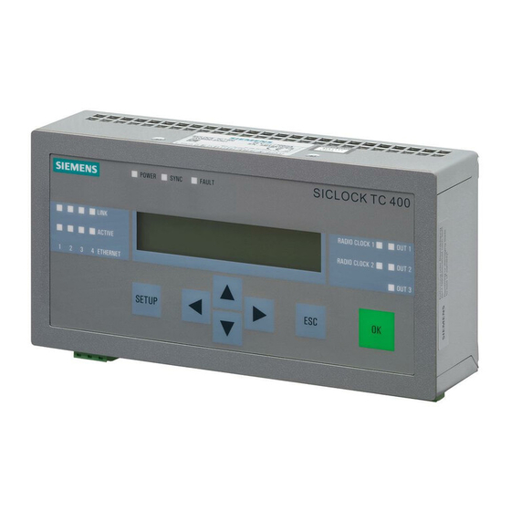
The following figures show the displays and operator controls as well as the con- nections of the SICLOCK TC 400. Figure 3-1 SICLOCK TC 400 - perspective view with front panel and ventilation grille Panel with operator controls and displays... -
Page 22: Connection Elements
Hardware Description Connection elements The following figure shows the connections of the SICLOCK TC 400. Figure 3-2 SICLOCK TC 400 - arrangement of the connections Terminal X1 - 24 V power supply Terminal X2 - connecting terminal for radio clocks, outputs and alarm See also Terminal assignment (Section 15.1). -
Page 23: Operator Controls And Displays
A Web-based configuration tool is avail- able for a wide range of configuration options, see Configuration Tool (Section 7). Figure 3-3 SICLOCK TC 400 front view 3-21 © Siemens AG 2007 All Rights Reserved ®... - Page 24 Displays POWER Green Ready to run SYNC Green SICLOCK TC 400 has been externally synchronized FAULT Alarm The associated message text is shown in the display. Flashing red Warning The associated message text is shown in the display. LINK (Port 1-4)
-
Page 25: Scope Of Delivery
Table 3-2 Scope of delivery of the individual device versions 2XV9450-2AR01 SICLOCK TC 400 single device with terminal strips connected at X1 and X2 Operating instructions on CD 2XV9450-2AR10 (SICLOCK TC 400 standard package) SICLOCK TC 400 single device with terminal strips connected at X1 and X2... - Page 26 Hardware Description 3-24 © Siemens AG 2007 All Rights Reserved ® SICLOCK TC 400...
-
Page 27: Technical Data
Operation Planning Overview of operation planning SICLOCK TC 400 has been designed for weather-protected, stationary operation in an industrial environment. The operating conditions surpass the requirements according to DIN IEC 60721- 3-3: • Class 3M3 (mechanical requirements) • Class 3K3 (climatic requirements) - Page 28 Use in residential areas and operation in the public network If you operate the SICLOCK TC 400 in residential areas or in the public network, you must ensure that it complies with the limit class B according to EN 55022 with regard to the emission of radio interference.
-
Page 29: Transport And Storage Conditions
1080 to 660 hPa (corresponds to an altitude of -1000 to 3500 m) Maximum temperature change 20° C/h Relative humidity 10 to 95% (at 25° C without condensation) 4-27 © Siemens AG 2007 All Rights Reserved ® SICLOCK TC 400... -
Page 30: Unpacking And Checking The Delivery
• Notify the delivery service in charge immediately if the package contents are incomplete or damaged. Warning Make sure that a damaged device is not installed and commissioned unintention- ally. 4-28 © Siemens AG 2007 All Rights Reserved ® SICLOCK TC 400... -
Page 31: Dimension Drawing
• Install the device in such a way that there is no danger, for example, of it falling out. • During assembly, please comply with the permissible mounting positions. See also Dimension Drawing (Section 14). 4-29 © Siemens AG 2007 All Rights Reserved ® SICLOCK TC 400... -
Page 32: Permitted Mounting Position
Figure 4-1 Horizontal mounting position 4.4.3 Fixing method The housing can be snapped onto DIN rails or fixed to SIMATIC S5 standard mounting rails. See also Installation overview (Section 5.1). 4-30 © Siemens AG 2007 All Rights Reserved ® SICLOCK TC 400... -
Page 33: Installation
Installation overview Figure 5-1 SICLOCK TC 400 - installation view The SICLOCK TC 400 should be installed in the control cabinet at an easily accessible position. The housing can be snapped onto DIN rails (EN 50022-35) or fixed to SIMATIC S5 standard mounting rails (6ES5 710-8maxx). - Page 34 Installation 5-32 © Siemens AG 2007 All Rights Reserved ® SICLOCK TC 400...
-
Page 35: Connecting
(PELV). The cable cross-section must be chosen to ensure that no damage can result from a cable overheating in the event of a short-circuit in the SICLOCK TC 400. For cable cross-section, see Connecting the power supply (Section 6.2). -
Page 36: Connecting The Power Supply
Ensure that the functional ground is connected correctly. Make sure the polarity is correct for DC voltage. Functional check After switching on, the POWER LED must show a green light. 6-34 © Siemens AG 2007 All Rights Reserved ® SICLOCK TC 400... -
Page 37: Connecting The External Synchronization
X2-9 RADIO CLOCK 1B X2-10 RADIO CLOCK 2A X2-11 RADIO CLOCK 2B Note If you are operating two radio clocks, connect the preferred model to RADIO CLOCK 1. 6-35 © Siemens AG 2007 All Rights Reserved ® SICLOCK TC 400... - Page 38 Receiving NMEA format − Telegram (faulty) Fault detected in telegram or telegram failure • No signal The connection of individual sources to the external synchronization is described in the following. 6-36 © Siemens AG 2007 All Rights Reserved ® SICLOCK TC 400...
-
Page 39: Siclock Gps1000
CLOCK 2" LED on the front panel should flash at approx. 1 Hz. After receiving for approximately three minutes the /Inputs/Input 1/Status (0.20.02) or /Inputs/Input 2/Status (0.21.02) parameter must change to "GPS". 6-37 © Siemens AG 2007 All Rights Reserved ® SICLOCK TC 400... -
Page 40: Siclock Dcfrs Industrial Version
DCF77 carrier frequency as possible. Do not mount the antenna close to drives, neon lamps, monitors and other emit- ters of interference. 6-38 © Siemens AG 2007 All Rights Reserved ® SICLOCK TC 400... -
Page 41: Siclock Gpsdec
CLOCK 2" LED on the front panel should flash at approx. 1 Hz. After receiving for approximately three minutes the /Inputs/Input 1/Status (0.20.02) or /Inputs/Input 2/Status (0.21.02) parameter must change to "GPS" or "DCF77". 6-39 © Siemens AG 2007 All Rights Reserved ® SICLOCK TC 400... -
Page 42: Third-Party Systems
Connecting 6.3.4 Third-party systems Third-party systems that fulfill the following requirements can be sued for the external synchronization of the SICLOCK TC 400. Requirements • Active radio clock signal with 20 mA rated current • Supported signals: − Demodulated DCF77 −... -
Page 43: Connecting The Time Receivers
Figure 6-6 OUTPUTs 1 and 2 as current interface Table 6-3 Terminals of OUTPUTs 1 and 2 Terminal Designation OUTPUT 1 GND OUTPUT 1 OUTPUT 2 OUTPUT 2 GND 6-41 © Siemens AG 2007 All Rights Reserved ® SICLOCK TC 400... - Page 44 An RS422 interface is available at OUTPUT 3 for a high-precision point-to-point connection. The connection is made as shown in Fig. 6-7. RS422 Figure 6-7 OUTPUT 3 RS422 Table 6-4 OUTPUT 3 terminals Terminal Designation OUTPUT 3A OUTPUT 3B 6-42 © Siemens AG 2007 All Rights Reserved ® SICLOCK TC 400...
-
Page 45: Redundant Point-To-Point Connections
Figure 6-8 Example with redundant time reception at OUTPUT 1 Further information Redundancy (Section 2.6) OUTPUT 1 and 2 redundant (Section 9.2.4) 6-43 © Siemens AG 2007 All Rights Reserved ® SICLOCK TC 400... -
Page 46: Connecting An Alarm Output And A Warning Output
Connecting Connecting an alarm output and a warning output The SICLOCK TC 400 automatically performs various functional tests during operation. When an error occurs, the appropriate messages are generated on the display. A distinction is made between alarms and warnings. -
Page 47: Configuration Tool
Configuration Tool The SICLOCK TC 400 configuration tool is available for the easy parameteriza- tion and configuration of the SICLOCK TC 400. The tool can be called as up Web interface via an Internet browser. With the configuration tool, you can view and change parameters online and offline, view archives and perform searches in them with filter criteria and load, save and change the parameterization of the SICLOCK TC 400 device. - Page 48 If a list is being considered, the entire list is read or written. Parameters are identified by their unique parameter number. The parameter number is always in three parts, e.g. 0.05.12. 7-46 © Siemens AG 2007 All Rights Reserved ® SICLOCK TC 400...
- Page 49 4. Save the configuration as parameter file (*.u600) on your PC with the button. Note In order to be able to access the last version of the SICLOCK TC 400 parameter- ization, we recommend that you save the current parameterization of SICLOCK TC 400 as *.u600 file before you make any changes.
-
Page 50: Menus
If the language set in the configuration tool is known to the device, then the parameter/archive is displayed in this language. If the language is not known to the device, the display is in the standard lan- guage. 7-48 © Siemens AG 2007 All Rights Reserved ® SICLOCK TC 400... - Page 51 Configuration Tool Table 7-1 Menus in the configuration tool Menu/Function Meaning/Note Help... Call the help system Version… Display the version information of the configuration tool 7-49 © Siemens AG 2007 All Rights Reserved ® SICLOCK TC 400...
-
Page 52: General Functions
Save of a parameterization/archive to the local file system The data (parameterization and archive) is saved in U600 format (*.u600). Save IP address of the SICLOCK TC 400 You enter the IP address of the device here. IP address Connect to a device The connection is established to the device with the specified IP address. -
Page 53: Establish/Disconnect Online Connection
Ignore event 7.2.1 Establish/disconnect online connection To establish an online connection to the SICLOCK TC 400: 1. Enter the IP address of the device in the toolbar. 2. Start the connection build-up by clicking the icon next to the IP address field. -
Page 54: Authorization
It is not possible to authorize yourself in offline mode with a password that is avail- able on the device, but is not contained in the offline authorization parameters. 7-52 © Siemens AG 2007 All Rights Reserved ® SICLOCK TC 400... -
Page 55: Parameters
Configuration Tool Parameters You can set and transfer parameters of the SICLOCK TC 400 in offline and online mode in the Parameters tab of the configuration tool. Figure 7-3 SICLOCK TC 400 configuration tool - parameters (1) Toolbar of the Parameters tab... - Page 56 Monitor actual values table is refreshed. (online connection See also Establish/disconnect online connection (Section 7.2.1). required) 7-54 © Siemens AG 2007 All Rights Reserved ® SICLOCK TC 400...
- Page 57 • Read parameter individually • Write parameter individually • Reset parameter to factory setting See Reading parameters / writing parameters / resetting parameters to factory settings (Section 7.3.4). 7-55 © Siemens AG 2007 All Rights Reserved ® SICLOCK TC 400...
- Page 58 If the configuration tool is not authorized or operated with a low authorization level, not all parameters are displayed. This restriction affects, for example, settings under "System". The access rights also change with the authorization level. 7-56 © Siemens AG 2007 All Rights Reserved ® SICLOCK TC 400...
-
Page 59: Sorting The Parameter Table
2. Click the symbol at the left side of the table next to the parameter. −> The parameter entries are hidden. Figure 7-4 Parameter table with shown and hidden entry 7-57 © Siemens AG 2007 All Rights Reserved ® SICLOCK TC 400... -
Page 60: Editing Parameters
Depending on the parameter/entry and operation status, the device checks whether the value change has been accepted. If the device rejects the new value, the old value is reset. 7-58 © Siemens AG 2007 All Rights Reserved ® SICLOCK TC 400... -
Page 61: Reading Parameters / Writing Parameters / Resetting Parameters To Factory Set
2. Select the desired parameter/entry in the parameter tree or parameter table. 3. Right-click the parameter or entry. −> The context menu opens. Left-click the desired function. Figure 7-7 Context menu to read, write or reset parameter 7-59 © Siemens AG 2007 All Rights Reserved ® SICLOCK TC 400... -
Page 62: Archive
You can load archive data from the device and save it as a file as well as evaluate and search the data with filter functions in the Archive tab of the configuration tool. Figure 7-8 SICLOCK TC 400 configuration tool - archives (1) Toolbar of the Archive tab... - Page 63 Clear include filter See Filter (Section 7.4.2). Remove all events from the exclude filter The events are moved to the include filter. Clear exclude filter See Filter (Section 7.4.2). 7-61 © Siemens AG 2007 All Rights Reserved ® SICLOCK TC 400...
-
Page 64: Sorting The Archive Table
−> Depending on the current sorting, the alphabetical order is reversed to either ascending or descending alphabetical order. The current sorting order is indicated by an arrow next to the column title: 7-62 © Siemens AG 2007 All Rights Reserved ® SICLOCK TC 400... -
Page 65: Filter
1. Click the button above the include or exclude filter. −> The include or exclude filter is cleared. The cleared events are now in the opposite filter for selection. 7-63 © Siemens AG 2007 All Rights Reserved ® SICLOCK TC 400... -
Page 66: Troubleshooting
Configuration Tool Troubleshooting The following is a list of FAQs and problem solutions for the SICLOCK TC 400 configuration tool. Table 7-5 Problem solutions for the configuration tool Question/Problem Cause/Remedy Authorization not possible in offline mode The data does not contain authorization parameters. You must perform an online authorization. - Page 67 You can refresh these values with the button or read them individually. Parameters (Section 7.3), Authorization (Section 7.2.2) and Reading parameters / writing parameters / resetting parameters to factory settings (Section 7.3.4). 7-65 © Siemens AG 2007 All Rights Reserved ® SICLOCK TC 400...
- Page 68 Configuration Tool 7-66 © Siemens AG 2007 All Rights Reserved ® SICLOCK TC 400...
- Page 69 Parameterization and Operation on the Device The SICLOCK TC 400 has a 2-line, alphanumeric backlit LCD display and automatic contrast con- trol for the display of date and time, messages and status. You can change important parameters for the commissioning and acknowledge messages via an integrated keypad.
- Page 70 The timeout for the switchover to the substitute synchronization can be set via the following parameter entry: /Redundancy/Redundancy/timeout (0.09.10) The timeout of the external synchronization can be set via the following parameter entry: /Inputs/Input 1/Monitoring/timeout (0.20.01) /Inputs/Input 2/Monitoring/timeout (0.21.01) 8-68 © Siemens AG 2007 All Rights Reserved ® SICLOCK TC 400...
- Page 71 If a persistent message that cannot be acknowledged is pending, you can change to the operating display temporarily with the ESC key. Backlighting The display backlighting is switched on for 10 minutes every time a key is pressed 8-69 © Siemens AG 2007 All Rights Reserved ® SICLOCK TC 400...
- Page 72 The following figure shows the basic operating sequence on the device. The initial situation is either the operating display or the message display on the device. Figure 8-5 Operating sequence 8-70 © Siemens AG 2007 All Rights Reserved ® SICLOCK TC 400...
- Page 73 −> A message appears that the password has not been accepted. Repeat the input with a correct password. The password input can be aborted at any time with ESC. 8-71 © Siemens AG 2007 All Rights Reserved ® SICLOCK TC 400...
-
Page 74: Parameter List
/Network Settings/Ethernet 4/IP Adapter 4 (0.05.04) • Version /Versions/Software Version (0.08.01) /Versions/Hardware Version (0.08.03) See also Parameterization (Section 9), Parameter Table (Section 10) and for acknowledging messages General functions (Section 7.2). 8-72 © Siemens AG 2007 All Rights Reserved ® SICLOCK TC 400... -
Page 75: Editing Dialog Box
Ethernet settings If you have selected an Ethernet setting in the parameter list, the following editing dialog box appears, e.g. for "ETH3 IP Address": ETH3 IP Address 192.168.3.30 8-73 © Siemens AG 2007 All Rights Reserved ® SICLOCK TC 400... - Page 76 The display alternates between the firmware and the processor version. You cannot make any settings in this dialog box. Press ESC or OK to return to the display of the parameter list. 8-74 © Siemens AG 2007 All Rights Reserved ® SICLOCK TC 400...
-
Page 77: Parameterization
Parameterization The following is a description of the frequently required settings. Further information Parameter Table (Section 10) Configuration Tool (Section 7) 9-75 © Siemens AG 2007 All Rights Reserved ® SICLOCK TC 400... -
Page 78: Linking The External Synchronization
Linking the external synchronization The external synchronizations can be linked via Ethernet as NTP server and/or as radio clock via point-to-point connections to the SICLOCK TC 400. Prerequisite for operation is at least one external synchronization. Additional external synchronization can be used as substitute synchronizations if a fault occurs, see Redundancy (Section 2.6). -
Page 79: Operation As Ntp Client
Parameterization 9.1.2 Operation as NTP client Four IP addresses of NTP servers can be assigned for SICLOCK TC 400 as NTP client. The servers are polled regularly and, on the basis of a strict selection strategy, a preferred server is selected. -
Page 80: Linking The Time Receivers
• 60 s with local time – for receivers that do not have a calendar The parameter entry "Multicast address" specifies the multicast IP address to be used. 9-78 © Siemens AG 2007 All Rights Reserved ® SICLOCK TC 400... -
Page 81: Simatic Method
Destination address The parameter entry /SIMATIC Method/Ethernet 1/destination address (0.15.01) specifies the send address of the SIMATIC method. Typically the broadcast address FF:FF:FF:FF:FF:FF is set. 9-79 © Siemens AG 2007 All Rights Reserved ® SICLOCK TC 400... -
Page 82: Output 1 To 3 Via Terminals
The required setting for the redundant configuration of the outputs is described in OUTPUT 1 and 2 redundant (Section 9.2.4). Further information Terminal assignment (Section 15.1) 9-80 © Siemens AG 2007 All Rights Reserved ® SICLOCK TC 400... -
Page 83: Output 1 And 2 Redundant
µs range and can be ignored. Large inaccuracies can occur when an external syn- chronization also supplies a faulty signal. 9-81 © Siemens AG 2007 All Rights Reserved ® SICLOCK TC 400... -
Page 84: Output Telegram (For Output 1 To 3)
You can specify the number of stop bits with the parameter entry /Outputs/Output Telegram/stop bits (0.19.01): 1 bit or 2 bits Further information OUTPUT 1 to 3 via terminals (Section 9.2.3) 9-82 © Siemens AG 2007 All Rights Reserved ® SICLOCK TC 400... -
Page 85: General Settings On The Device
Difference between TAI and UTC You can read out the difference between atomic time TAI and world time UTC in seconds with the /Time/Advanced/Atomic Time TAI/Offset From UTC To TAI (0.09.01) parameter. 9-83 © Siemens AG 2007 All Rights Reserved ® SICLOCK TC 400... -
Page 86: Synchronization
If required, disconnect the active external synchronization first or delete the server address for the NTP client operation from the /NTP Client/NTP Server List[4] (0.18.02) parameter. 9-84 © Siemens AG 2007 All Rights Reserved ® SICLOCK TC 400... -
Page 87: Display
For Standard Protection (2.06.02) parameter. You can reset the parameters to the factory settings with the /System/Reset (0.06.04) parameter. Exceptions are parameters such as network addresses, authorizations, etc. 9-85 © Siemens AG 2007 All Rights Reserved ® SICLOCK TC 400... -
Page 88: Temperature
/Environ- ment/Advanced/Battery/disconnect (0.25.01). During power up, the SICLOCK TC 400 checks once whether the battery has been disconnected after at least 30 minutes of operation. If required, the battery is then automatically connected and a message output. -
Page 89: Parameter Table
Parameter Table Table 10-1 List of the parameters of SICLOCK TC 400 Access Parameter Entry Value Range / Default / No. Time Local Time time and date 0.09.04 UTC Time time and date 0.09.02 Time Zone offset from UTC to zone time... - Page 90 Parameter Table Table 10-1 List of the parameters of SICLOCK TC 400 Access Parameter Entry Value Range / Default / No. Time/Advanced/Atomic Time TAI TAI Time time and date 0.09.03 Offset From UTC To TAI offset Min: -32768 s Max: +32767 s 0.09.01...
- Page 91 Parameter Table Table 10-1 List of the parameters of SICLOCK TC 400 Access Parameter Entry Value Range / Default / No. Redundancy Redundancy preference Min: Master Max: Slave 0.09.10 Default: Master timeout Min: 10 min Max: 720 min Default: 30 min...
- Page 92 Parameter Table Table 10-1 List of the parameters of SICLOCK TC 400 Access Parameter Entry Value Range / Default / No. Network Adapter 2 hardware address Min: 00.00.00.00.00.00 Max: FF.FF.FF.FF.FF.FF 0.05.06 Default: 00.00.00.00.00.00 Line State Adapter 2 link Min: Max: down 0.09.14...
- Page 93 Parameter Table Table 10-1 List of the parameters of SICLOCK TC 400 Access Parameter Entry Value Range / Default / No. Network Settings/Ethernet 4 IP Adapter 4 IP address Min: 0.0.0.0 Max: 255.255.255.255 0.05.04 Default: 192.168.4.40 subnet mask Min: 0.0.0.0 Max: 255.255.255.255...
- Page 94 Parameter Table Table 10-1 List of the parameters of SICLOCK TC 400 Access Parameter Entry Value Range / Default / No. Ethernet 2 mode Min: Max: S5-compat., every 10 s 0.15.02 Default: send condition Min: Max: only if synchronized Default:...
- Page 95 Parameter Table Table 10-1 List of the parameters of SICLOCK TC 400 Access Parameter Entry Value Range / Default / No. NTP Client NTP Client operation Min: Max: 0.18.01 Default: NTP Server List[4] IP address Min: 0.0.0.0 Max: 255.255.255.255 0.18.02 Default: 0.0.0.0...
- Page 96 Parameter Table Table 10-1 List of the parameters of SICLOCK TC 400 Access Parameter Entry Value Range / Default / No. Inputs/Input 2 Status signal Min: no signal Max: telegram (faulty) 0.21.02 Default: no signal Monitoring monitor input Min: Max: alarm 0.21.01...
- Page 97 Parameter Table Table 10-1 List of the parameters of SICLOCK TC 400 Access Parameter Entry Value Range / Default / No. Output 2 signal to output Min: Max: serial telegram 0.13.01 Default: inverted Min: Max: Default: pretrigger Min: 0 ns...
- Page 98 Parameter Table Table 10-1 List of the parameters of SICLOCK TC 400 Access Parameter Entry Value Range / Default / No. Display View language Min: German Max: English 0.10.01 Default: German time Min: local time Max: atomic time TAI Default:...
- Page 99 Parameter Table Table 10-1 List of the parameters of SICLOCK TC 400 Access Parameter Entry Value Range / Default / No. Hardware Version A2B number Min: Max: 4294967295 0.08.03 Default: release number Min: Max: 65535 Default: serial number The access symbols display the access possibility at the highest authorization level.
- Page 100 Parameter Table 10-98 © Siemens AG 2007 All Rights Reserved ® SICLOCK TC 400...
-
Page 101: Service And Maintenance
The battery can be specifically disconnected for storage which significantly increases the battery life. During power up, the SICLOCK TC 400 checks once whether the battery has been disconnected after at least 30 minutes of operation. If required, the battery is then automatically connected and a message output. -
Page 102: Software Update
Service and Maintenance 11.3 Software update You can obtain information and any software updates for your SICLOCK TC 400 from the Product Support. See also Preface. 11-100 © Siemens AG 2007 All Rights Reserved ® SICLOCK TC 400... -
Page 103: Messages
See also Battery (Section 9.3.6). Bootloader has been updated System and The bootloader has been successfully installed. information Bootloader has NOT been updated System and The bootloader could not be installed. information 12-101 © Siemens AG 2007 All Rights Reserved ® SICLOCK TC 400... - Page 104 The exact specification of the error is contained in the message text and may be of importance for the support (hotline). Processor has been updated System and A processor update has been performed and the processor has been updated. information 12-102 © Siemens AG 2007 All Rights Reserved ® SICLOCK TC 400...
- Page 105 A processor update has been performed, but the processor could not be updated. information Hardware time set Information The SICLOCK TC 400 internal hardware clock has been set. No useable NTP server Information A preferred server has not been found.
- Page 106 (E.g. firmware update, Web data update, etc.) Time initialized by hardware Application An initial synchronization of the clock module has been performed. Time set by HMI Application Time domain(s) has(have) been changed via HMI 12-104 © Siemens AG 2007 All Rights Reserved ® SICLOCK TC 400...
-
Page 107: Technical Data
Technical Data Table 13-1 Technical data of the SICLOCK TC 400 Dimensions 180.0 x 88.9 x 47.0 (WxHxD in mm) Weight Approximately 750 g Supply voltage 24 VDC (-15% to +20%) at X1 Power supply Continuous current max. 0.7 A Transient voltage interruption Max. - Page 108 Technical Data Table 13-1 Technical data of the SICLOCK TC 400 Service life during storage, con- < 6 years, see Battery (Section 11.1) nected Electromagnetic compatibility (EMC) Interference emission EN 55022 Class A, FCC Class A Immunity to interference EN 55024...
- Page 109 Technical Data Table 13-1 Technical data of the SICLOCK TC 400 Status displays on the device Display 2-line, alphanumeric backlit LCD display and temperature-compensated contrast control LEDs 4x orange LEDs for Ethernet port link-up 4x green LEDs for Ethernet port activity...
- Page 110 Technical Data 13-108 © Siemens AG 2007 All Rights Reserved ® SICLOCK TC 400...
-
Page 111: Dimension Drawing
Dimension Drawing Figure 14-1 Dimension drawing 14-109 © Siemens AG 2007 All Rights Reserved ® SICLOCK TC 400... - Page 112 Dimension Drawing 14-110 © Siemens AG 2007 All Rights Reserved ® SICLOCK TC 400...
-
Page 113: Circuit Diagrams
Radio Clock 2 COMMON ALARM OUT WARNING OUT active Radio Clock 1 48 V active Radio Clock 2 48 V Figure 15-1 Terminal assignment of the SICLOCK TC 400 15-111 © Siemens AG 2007 All Rights Reserved ® SICLOCK TC 400... - Page 114 Circuit Diagrams 15-112 © Siemens AG 2007 All Rights Reserved ® SICLOCK TC 400...
-
Page 115: Spare Parts / Accessories
Table 16-1 Spare parts and accessories with order numbers Order number Single device SICLOCK TC 400 single device 2XV9450-2AR01 Packages SICLOCK TC 400 standard package, contains GPS1000 2XV9450-2AR10 SICLOCK TC 400 DCF77 2XV9450-2AR20 Spare parts for GPS1000 GPS1000 E10433-E9910-H100 Mounting frame for GPS1000... - Page 116 Spare Parts / Accessories 16-114 © Siemens AG 2007 All Rights Reserved ® SICLOCK TC 400...
-
Page 117: Appendix
The requirements regarding noise immunity according to EN 61000-6-2:2001 are met when you connect an I/O device suitable for an industrial environment. I/O devices may only be connected via shielded cables. A-115 © Siemens AG 2007 All Rights Reserved ® SICLOCK TC 400... -
Page 118: Certificates And Approvals
DIN ISO 9001 certificate The quality assurance system for the entire product process (development, pro- duction, and marketing) at Siemens fulfills the requirements of DIN EN ISO 9001. This has been certified by DQS (the German society for the certification of quality management systems). -
Page 119: Esd Guidelines
Any damage that occurs to a module as a result of overvoltage is generally not recognized immediately and only comes to light after the equipment has been operating for some time. B-117 © Siemens AG 2007 All Rights Reserved ® SICLOCK TC 400... -
Page 120: Electrostatic Charging Of Persons
These values comply with the specifications in IEC 801-2. Figure B-2 Electrostatic voltage that can accumulate on operating personnel B-118 © Siemens AG 2007 All Rights Reserved ® SICLOCK TC 400... -
Page 121: Basic Measures To Protect Against The Discharge Of Static Electricity
If you have to take measurements on a module, make sure that you first discharge any static that may have accumulated in your body. To do this, touch a grounded metal object. Only use grounded measuring instruments. B-119 © Siemens AG 2007 All Rights Reserved ® SICLOCK TC 400... - Page 122 ESD Guidelines B-120 © Siemens AG 2007 All Rights Reserved ® SICLOCK TC 400...
-
Page 123: List Of Symbols
Download parameters of the connected device without parameter descrip- tion Upload parameters Transfer writeable values of the loaded parameters to the connected device Monitor actual values Refresh actual value display Write protection C-121 © Siemens AG 2007 All Rights Reserved ® SICLOCK TC 400... - Page 124 Change exclude-include view Move event from the include to the exclude filter and vice versa Clear include filter / Clear exclude filter Remove all events from the include/exclude filter C-122 © Siemens AG 2007 All Rights Reserved ® SICLOCK TC 400...
-
Page 125: D Glossary
There are various authorization levels. The current authorization status is displayed in the password entry field in differ- ent colors; red is the lowest authorization level. See Password. D-123 © Siemens AG 2007 All Rights Reserved ® SICLOCK TC 400... - Page 126 • Application • Information • Warning External synchronization External time source that is used for the synchronization of the SICLOCK TC 400. Filter Searches can be performed for specific events in the archive with an include and exclude filter. See Archive.
- Page 127 Glossary Device The SICLOCK TC 400 plant central clock is described as a device. Pulse converter All products of the SICLOCK range that convert physical levels without changing the information are designated as pulse converters. Examples of pulse converters: SICLOCK EOPC, SICLOCK PCON, SICLOCK DCFHF, SICLOCK DCFS7 inter- face.
- Page 128 SICLOCK TC 400 configuration tool Web interface for the parameterization and searching in the archive of a SICLOCK TC 400 device via an Internet browser. u600 file The configuration tool can open and save parameters and archives in the form of *.u600 files.
- Page 129 The term Time synchronization of plants is always used to describe when several components of a plant are synchronized with products of the SICLOCK range. Zone time The zone time is the zone time derived from UTC. D-127 © Siemens AG 2007 All Rights Reserved ® SICLOCK TC 400...
- Page 130 Glossary D-128 © Siemens AG 2007 All Rights Reserved ® SICLOCK TC 400...
-
Page 131: Index
Status of synchronization, 8-68 Leap seconds, 9-84 Symbols, C-121 Local time, 9-83 Synchronization, 9-84 Messages, 12-101 TAI time, 9-83 Microstepping, 9-85 Terminal assignment, 15-111 Mounting position, 4-30 Time receivers, 9-78 Index-129 © Siemens AG 2007 All Rights Reserved ® SICLOCK TC 400... - Page 132 Index Time zone, 9-83 TTY, 6-41 u600 file, 7-47 UTC time, 9-83 Warning output, 6-44 Warnings, 12-101 Index-130 © Siemens AG 2007 All Rights Reserved ® SICLOCK TC 400...
- Page 134 Siemens AG Electronic Design and Manufacturing Services Frauenauracher Str. 98 91056 ERLANGEN GERMANY www.siemens.com/siclock...