Table of Contents
f
Save This Manual
-_
For Future Reference
ModeJ No.
113,232240
Jointer/Planer
with Legs and Motor
Serial
Number
Model
and
serial
numbers
may be found on the back of
the jointer base.
You should record both model
and serial number
in a safe
place for future use.
YOU
SAFETY
READ ALL
INSTRUCTIONS
CAREFULLY
CONTRACTOR
ES
6-1/8 I
JOmNTEPJPLANER
Part No, SP5971
• assembly
. operating
• repair parts
Sears, Roebuck
and Co., Hoffman
Estates,
IL. 60179 U.S.A.
J
Printed inTaiwar_
Table of Contents

Related Manuals for Craftsman 113.232240


Summary of Contents for Craftsman 113.232240
- Page 1 Save This Manual For Future Reference ModeJ No. 113,232240 Jointer/Planer with Legs and Motor Serial Number Model serial numbers may be found on the back of the jointer base. CONTRACTOR You should record both model and serial number in a safe 6-1/8 I place for future use.
-
Page 2: Safety Instructions For Jointer/Planer
!:i! !ii!i i ¸I!! ii/! i ill ! YEAR WARRANTY ON CRAFTSMAN STATIONARY TOOL ie toa defect in material or workmanship within one year from the date purchasei CONTACT THE NEAREST SEARS SERVICE CENTER iN THE UNITED STATES : Sears will repair it, free of charge, This warranty applies only while this prodUct is in the United States. -
Page 3: Before Each Use
Before Each Use Inspect your jointer/ptaner. switch off and key removed, pull the cutter guard open and let go. tf the guard doesn't smoothly swing closed, WARNING: The 2-1/2 inch jointer/planer pulley and contact Sears Service Department. the 3-112 inch motor pulley furnished will run the •... -
Page 4: Inspect Your Workpiece
Safety tnstructions For Jointer/Planer (contin, Inspect your wotkpiece. - Never cut Freehand, Guide your workpiece solidly against the fence and table top. • Make sure there are no nails or foreign objects in the - Make sure there's no debris between the workpiece part of the workpiece to be cut. -
Page 5: Motor Specifications And Electrical Requirements
Ouffeed Table Freehand The section of a jointer bed which supports the workpiece Using the tool without holding the workpiece firmly after it passes over the cutter head. against the fence and table. This can let the workpiece twist and kick back and must never be attempted. Planing Removing wood from the widest surface or face of a board so as to make it flat and smooth. -
Page 6: General Electrical Connections
Motor Speclfic.tions and Eiectr, cat Requirements (continued) i : i DANGER: To aVoid electrocution: U_e only identical replacement parts when ser- vicing! Servicing should be performed by a qualified service technician. 2i Do not use in rain or where floor is wet. This tool is intended for indoor residential :only. -
Page 7: Changing Motor Voltage
Changing Motor Voltage 3. Remove and discard the electrical tape from the wire WARNING: If not properly grounded, this tool can nuts. Remove wire nuts. cause an electrical shock, particularly when used 4. Reconnect the leads as shown in the "Wiring Diagram" in damp locations, in proximity to plumbing, or out of doors. -
Page 8: Table Of Contents
Table of Contents Safety Instructions For Jointer/Planer ......2 Getting to Know Your JointedPlaner ....17-18 Safety Signal Words ....... : ...._ ..2 Alignments ............19-22 Before Using the JointedPlaner ....;....2 Cutter Knife Adjustments/Replacement ....19 When Installing Or Moving the Jointer/Planer. -
Page 9: Table Of Loose Parts
Unpacking If you are missing any parts, chect_ packing material for WARNING: To avoid injury from unexpected starl- those items. ing or electrical shock, do not plug the power cord WARNING: if any parts are missing, do not attempt into a power source outlet during Unpacking, until to assemble the jointerlplaner. -
Page 10: List Of Loose Parts
Unpacking and Checking = Contents Ccontinued) ..List of Loose Parts... -
Page 11: List Of Loose Parts (From Bag Assembly)
List of Loose Parts (From Bag Assembly) Rod-Knife Gauge 3ram Hex-L Wrench Wrench 8mm/lOmm Wrench 12mm/14mm Gauge-Knife (2) Leveling Feet (4) Wire Nut Retaining Ring (4) Switch Key (t) © External Washer (8) Washer (34) Lock'washer (3) Lockwasher (30) Lockwasher #8 (2) 1/4"... -
Page 12: Assembly
i_ :¸ _ i ::i: :i • : • 1 WARNING: Although compact, this tool is heavy. l:To avoid back injury, get help whenever you have : I to liftthe tool Assemble The Stand Carriage Bolt Washer Lockwasher 5/16-18 x 314 13132 5/16 5/16-18... -
Page 13: Assemble Motor To Stand
2. Install lower motorbrackets as shown using (4) 5/16-18 carriage bolts, (4) 13/32 washers, (4) 5/16 Iockwashers and (4) 5/16-18 hex nuts attach lower bracket on top of stiffeners. Hand tighten only. 3. Install vertical motor bracket using (2) 5/16-18 carriage bolts, (2) 13/32 washers, (2) 5/16 Iockwashers and (2) 5/16-18 hex nuts attach vertical bracket at the bottom only onto slots of lower motor bracket as shown. -
Page 14: Assemble Switchbox To Stand
Until pulley hits shoulder on shaft. Tighten the two set screws in:the pulley with supplied 3ram Hex "L" wrench. 3 With the leg stand on its side, set the motor on the ver- tical motor bracket, aligning it to the bottom of the slots so it won't Slip when the stand is tilted upright. -
Page 15: Assemble Fence To Bed
Assemble Fence To Bed 1. Remove the two nuts and the washer from the bolt on underside of the fence assemMy, \_" 114 Turn 2, Carefully lift the fence and place it onto the bed, lining Key Slot up the key slot in the fence with the key in the fence support. -
Page 16: Adjusting Guard Spring
Assembly (continued) Adjusting Guard Spring 1. Remove the pan head screw from bottom of the guard post, 2. Remove tension on.guard by turning tension knob clockwise. Pull up on guard to remove. 3, Add tension to the cutter head guard in 1/2 turn incre- ments by turning the tension knob and reinserting the guard post. -
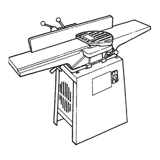
Page 17: Getting To Know Your Jointedplaner
Getting to Know Your Jointer/Planer (sharper) part of blade. WARNING: For your own safety always lock the switch "OFF" when jointertplaner is not in use. 4.90 ° and 45 ° Fence Stops Remove key and keep it in a safe place, also, in the When adjusted properly, these... - Page 18 i¸¸!:/ i¸ !!i ii!!i ill _ ill!i !! i _ /i!i _ (continued) t-----"---"- ICAUTION: Beforeturning switch "ON", make sure I theblade guard is correctly installed and operat- 'ling properly. 12. On-Off Switch Turns the tool on and off. The "yellow button" is a key. When it is inserted in the switch lever, the power may be turned ON and OFF.
-
Page 19: Alignments
Alignments ......Cutter Knife Alignment/Adjustments Do not let your hand or fingers touch the cutter I WARNING: The cutter knives are extremely sharp. I knives. Tools Needed 8ram open end wrench (Supplied). - Unplug jointer/planer, made sure switch is "OFF" and plug is not con- I WARNING: To avoid injury from accidental start, ] nected to power source outlet. -
Page 20: Cutter Knife Sharpening
Alignments (continued) Cutter Knife Sharpening The knives can be honed individually with an ordinary oil- stone. Make sure your oilstone is not worn in the center. It must be flat. Be sure to remove the burr on the flat side. 11/16 In Wide WARNING: The cutter knives are extremely sharp. -
Page 21: Outfeed Tableadjustment
Outfeed TableAdjustment To checkthis alignment proceed as follows: WARNING: To avoid injury from accidental start, made sure switch is "OFF" and plug is not con- nected to power source outlet. I. Raise or lower the outfeed table as required, by turning .a//A '_.//-4 f //._ ouffeed table... -
Page 22: Adjusting Table Gibs
Alignments (continued) Adjusting Table Gibs Lock Nuts "Gibs" are provided to take up all play between the mat- ing dovetail ways of the base and infeed and outfeed tables of your jointer. Proper gib adjustment is necessary for the correct functioning of the jointer, The gibs on your machine were adjusted at the factory and should require no further adjustment. -
Page 23: Safety Instructions For Basic Jointer/Planer Operation
Safety instructions for Basic Jointer/Planer Operation ' Before Each Use: The top should move toward the infeed table, Call your Sears Service Department for help ff the cutter head InSpect your jointer/planer. turns the wrong way. . WARNING: The 2-1/2 inch jointer/pianer pulley and -Keep JointeriPtaner interior, free of wood chips and... -
Page 24: Whenever Jointedptaner Is Running
Safety instructions for Basic Jointer/Planer Operation (continued) - When jointing o r beveling: and its supports. - Never joint or bevel workpieces less than 3/4 inch - Use extra caution with large, very small or awkward wide or 1/4 inch thick. workpieces. -
Page 25: Feedin G The Workpiece
Feeding the Workplace Hold the board firmly down on both tables and against the f_nce. Keep fingers c_ose togelher. Feed the board at a continuous even rate of speed until the cut is made along the entire length of the board. Any hesitation or stopping could cause a "step"... -
Page 26: Jointing
Basic Jointer/Planer Cutting Operations (continued) ..,,.,, Jointing_ Joiniing is the removal of wood along the edge'of a piece Of wood so as to make that edge straight, smooth and squal_e to the wood face which is against the fence. To ensure a square cut, the workpiece face must be held flat against the fence throughout the entire cut. -
Page 27: Support Long Workpieces
Support Long Workpieces To avoid injury from slips or kickbacks, use extra sup- ports (tables, saw horses, etc.) at both infeed and out- feed ends if your workpiece if hard to hold down to the table. ,,,,,, ,,,,, ,, Using the Hold-Down/Push-Blocks Always use the hold_down/push-blocks when jointing or rabbeting wood that is narrower than 3 inches or planing... -
Page 28: Sliding Fence Operation
Clean them with Craftsman Gum and Pitch Remover. and should be blown out or "vacuumed" frequently to pre- Apply a thin coat of paste type wax to the tables and the vent interference with normal motor ventilation, fence so that the wood slides easily while feeding. -
Page 29: Lubrication
Lubrication Unplug the joint__c_ start suddenly. You could be badSy hurt, The ball bearings in this machine are packed with grease at the factory, They required no further lubrication, The following parts should be ,oiled occasionally with SAE No. 20 or No. 30 engine oil. 1, Dovetail spacer and dovetail siide. -
Page 30: Troubleshooting Guide
i::¸¸¸ i¸!:::://;/: :: :::: i:' Troubleshooting Guide WARNING:" For your own safety turn switch "OFF" and remove plug from power source outlet before trou- I b!eshooting your jointerlplaner :General Trouble Probable Cause Remedy Motor will not run 1. Def'ective On-Off switch 1. -
Page 31: Motor
Motor NOTE: Motors used on wood working tools are particularly susceptible to the accumulation of sawdust and wood chips and_should be blown out or "vacuumed" frequently to prevent interference wi_t_ normal motor ventilation. Trouble Remedy Probable Cause Excessive noise t. Motor 1, Have moto_ _checked by qualified service techni- cian. - Page 32 Repair Paris Parts List for Craftsman 6-118" Jointer/Planer Model No. 113.232240 Figure 1 ii_:_••i_il;i;::, ¸¸_ ..;,:L7 : '_ i _...
-
Page 33: Repair Parts
Repair Parts Parts List for Craftsman 6-118" Jointer/Pianer Mode! No, 113.232240 Figure 1 Always order by Part Number - Not by Key Number Part No. Description Part No. Description 824919 * Screw Pan Hd 1/4-20 x 1/2 Guard Cutter STD512505 .. - Page 34 Repair Parts Parts List for Craftsman 6-1/8" Jointer/Planer Model No. 113.232240 Figure 2 Part No. Description Description Key Part.o. :82488_ Screw 1/4-28 x 7ram STD502503 '"* Soc Set Screw 1/4-20 x 3/8 824885 824888 Wed ge Pulley 9*2293 : STD852010 i 1"Blade...
- Page 35 Repair Parts ..,rll..i ....rl,=Ni, ii1,1,111 iii IN Parts List for Craftsman 6-1/8" Jointer/Planer Model No. 113.232240 Figure 3...
- Page 36 Alwaysorderby PartNumber - Not by Key Number Part No. Part No. Description Description 824895 Slide Fence 824082 Screw Pan'Hd 3/16-24-X 1/4 "' 102817 Screw Set Dog Point 1/4-20 x 1/2 824884 Trunnion 824900 Knob 824893 Nut Bevel Lock 824899 Rod Knob 824882 Fence 824896...
- Page 37 Repair Parts ......,,i, ii!1,11 Parts List for Craftsman 6-118" JointedPtaner Model No. 113.232240 Figure 4...
- Page 38 Parts List for Craftsman 6-1/8" Jointer/Planer Model No. 113.232240 Figure 4 Always order by Part Number - Not by Key Number Part No, Description Part No. Description , ,j 824905 Bracket Upper STD551037 " '* Washe'r 3/8 x 3/4 x 3/32 ' "...
- Page 39 Repair Parts ..Parts List for Craftsman 6-118" JointedPlaner Model No. 113.232240 Figure 5 Always order by Part Number - Not by Key Number Part No. Description Description Part No. , ;,,, ..* Nut #8-32 STD541008 9-22255 Key Switch...
- Page 40 iiii i,=,, iii i_,,11 ! ,, CONTRACTOR 6-1/8 INCH JOmNTER/PLANER Model No. Forthe repair or replacement parts you need Call 7 am - 7 pro, 7 days a week 113.232240 t -800-366=PART Jointer/Planer (1-B00-366-7278) with Legs and Motor For in-home major brand repair service Call 24 hours a day, 7 days a week 1-800-4-REPAIR (1-800-473-7247)