Available languages
Available languages
Quick Links
GE Model 19234
www.jascoproducts.com
Wireless Door Chime Kit
Installation Instructions AC Wireless Chime Kit
Required Tools: Small flat blade screwdriver, drill,
1/16” drill bit, and phillips screwdriver.
Included Hardware:
(2) 3x20mm screws
(1) Double sided adhesive pad
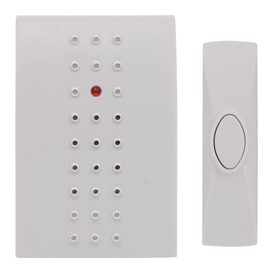
The wireless door chime kit has two components:
Battery Operated
Chime (Receiver)
PushButton (Transmitter)
Plugs into 120V outlet Battery included
Setting The House Security Code
Each chime component has 3 jumpers for setting the
house security code. In most cases you will not need
to change the factory settings for the house security
code. If your chime activates intermittently or does not
work at all, you may be able to solve the problem by
changing your security code.
Pushbutton
House Code
Jumpers
19234-1.indd 1
The chime and pushbutton must be set to the same
house security code for the combination to operate
together.
1. Remove power from the chime.
2. To remove the batteries from the pushbutton,
open the pushbutton case as shown below.
Pushbutton
House Code
Jumpers
Pushbutton Jumpers
3. Locate the House Security Code door and screw
located on the back of the Chime. Remove the
screw and take off the door.
4. Locate the chime and pushbutton jumpers shown
above.
5. To change the house code, add or remove jumpers
as needed. It is recommended to change only one
jumper at a time and then test the system for proper
operation. The jumpers on the chime and pushbutton
must match exactly.
Wireless push button battery
To install or replace the battery in the wireless push
button.
1. Remove the back cover of the push button.
2. Install the A23 (12 volt) battery with the negative
side of the battery (-) toward the spring and the
positive side of the battery (+) toward the positive
battery holder as shown below.
3. Replace back cover as shown below.
Push Button Mounting Instructions
Note: Avoid mounting on metal surfaces, as it may
result in a reduced range of transmission. Do not mount
in an area where exposed to direct rain.
a. Removing the back cover
b. Replacing the back cover
Mounting Push Button
1. Push buttons are typically mounted at the same
height as the door knob or handle (between 36” and
44” above the floor).
2. Before mounting, choose a mounting location that
is not farther than 150 feet from the chime unit
location.
Not further than 150 feet
3. Before placing the pushbutton where you would like
to mount it, place the chime as close to final position
as possible. Test the operation before drilling. If it
works, mount the push button. If it does not work,
see TROUBLESHOOTING.
4. Use back cover of push button as a template to mark
two screw holes.
4
5
6
8
5. Drill two holes with 1/16” size drill in marked
locations.
6. Secure back cover to the mounting surface with two
supplied mounting screws.
7. Install the supplied 12V battery observing proper
polarity. (see battery installation section)
8. Press front housing onto back cover.
9. Test operation. If the chime does not work, see
TROUBLESHOOTING.
If you do not want to drill holes in your door frame, you
can use the supplied double sided tape for installation.
1. Clean all mounting surfaces with a 50/50 mixture of
isopropyl alcohol.
2. Remove the backing from one side of the double
sided tape and press the exposed side against the
back plate of the push button.
3. Remove the other backing strip and press the
exposed side against the door frame where you want
the button installed.
Power Indicator
On/Off Switch
Operation
1. Plug the chime into a 120V AC outlet and slide the
power switch to the “On” position to turn on the
chime. The red LED power indicator will light.
2. Gently press transmitter button to sound chime.
Troubleshooting
Chime doesn’t work:
1. Make sure push button switch is depressed and held
for at least 1 second.
2. Make sure house code switches 1-4 on chime and
push button match exactly.
3. Verify battery orientation in push button.
4. Try fresh batteries.
5. Make sure chime is not farther than 150 feet away
from push button.
6. Ensure push button is not mounted on metal, near
metal studs, or near the floor.
7. Try a new location for the chime.
Functional range may be adversely affected by one or
more of the following factors: weather, radio frequency
interference, low transmitter battery and obstructions
between the transmitter and receiver.
This device complies with Part 15 of the FCC rules.
Operation is subject to the following conditions:
1. This device may not cause harmful interference, and
2. This device must accept interference received,
including any interference that may cause undesired
operation.
For technical support contact Jasco Products
Company at 1-800-654-8483
or www.jascoproducts.com
Made in China/Hecho en China
is a trademark of
General Electric Company
and is used under license to
Jasco Products Company LLC,
10 E. Memorial Rd.,
Oklahoma City, OK 73114.
www.jascoproducts.com
19234

Related Manuals for GE 19234


Summary of Contents for GE 19234
- Page 1 GE Model 19234 The chime and pushbutton must be set to the same Push Button Mounting Instructions 9. Test operation. If the chime does not work, see www.jascoproducts.com house security code for the combination to operate Note: Avoid mounting on metal surfaces, as it may TROUBLESHOOTING. together. result in a reduced range of transmission. Do not mount If you do not want to drill holes in your door frame, you in an area where exposed to direct rain. can use the supplied double sided tape for installation. Wireless Door Chime Kit 1. Remove power from the chime. 1. Clean all mounting surfaces with a 50/50 mixture of 2. To remove the batteries from the pushbutton, a. Removing the back cover isopropyl alcohol. open the pushbutton case as shown below. 2. Remove the backing from one side of the double Installation Instructions AC Wireless Chime Kit sided tape and press the exposed side against the back plate of the push button. Required Tools: Small flat blade screwdriver, drill, 3. Remove the other backing strip and press the...
- Page 2 GE Modelo 19234 2. Instale la batería A23 (12 voltios) con el extremo 3. Antes de colocar el pulsador en el lugar escogido Solución de problemas www.jascoproducts.com negativo de la batería (-) contra el resorte y el para el montaje, coloque el timbre tan cerca como extremo positivo de la batería (+) contra el contacto sea posible de la ubicación definitiva. Compruebe Jumpers de El timbre no funciona: Timbre Inalámbrico positivo del portabatería como se muestra abajo. su correcto funcionamiento antes de practicar los código de casa 1. Asegúrese de mantener presionado el interruptor del agujeros. Si funciona bien, monte el pulsador. Si no de case pulsador por lo menos durante 1 segundo. para Puerta funciona, ver SOLUCIÓN DE PROBLEMAS. 2. Asegúrese de que los interruptores 1-4 del código 4. Use la tapa posterior del pulsador como plantilla para de casa en el timbre y en el pulsador coinciden de marcar los lugares de los agujeros para los tornillos. manera exacta. Instrucciones de instalación Timbre inalámbrico de 3. Compruebe la orientación de la batería en el...