
Related Manuals for Emerson Liebert IntelliSlot IS-WEB485ADPT


Summary of Contents for Emerson Liebert IntelliSlot IS-WEB485ADPT
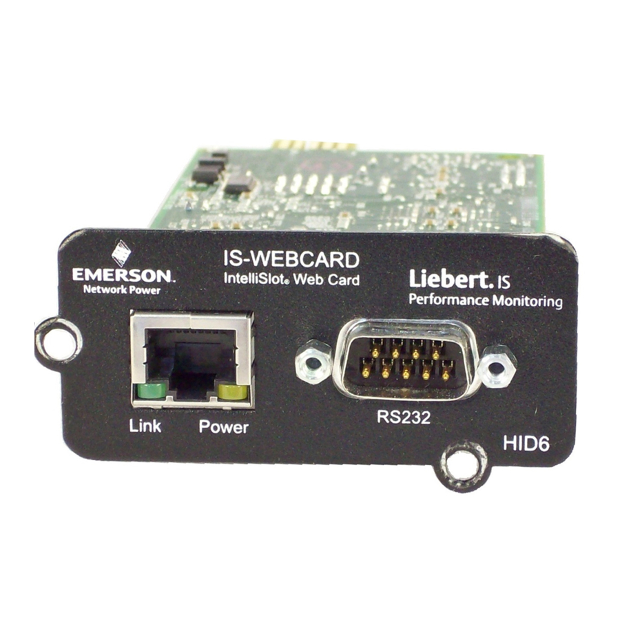
- Page 1 Liebert IntelliSlot Web Cards ® ® Installation Manual – Liebert IntelliSlot Web Card, Liebert IntelliSlot Web Card-LB, Liebert IntelliSlot Web Card-LBDS, Liebert IntelliSlot Web/485 Card-ADPT Monitoring For Business-Critical Continuity™...
-
Page 3: Table Of Contents
MPORTANT AFETY NSTRUCTIONS ............2 NTRODUCTION Compatibility With Liebert Equipment . - Page 4 UPPORT NFORMATION View Web Card Information ..........39 Events and Parameters .
-
Page 5: Important Safety Instructions
SAVE THESE INSTRUCTIONS WARNING Only a qualified service professional should install these products. Liebert recommends having an Emerson Network Power Liebert Services representative perform the installation in large UPSs. Contact Liebert Services at 1-800-LIEBERT (1-800-543-2378). WARNING Risk of electric shock. Can cause equipment damage, injury or death. -
Page 6: Introduction
NTRODUCTION The Liebert IntelliSlot ® ® AC Power and Precision Cooling systems. Liebert IntelliSlot Web cards bring SNMP, Telnet and Web-management capability to many models of Liebert power and cooling equipment. The cards employ an Ethernet network to monitor and manage a wide range of operating parameters, alarms and notifications. -
Page 7: Web Support
Web Support The Liebert IntelliSlot Web card delivers Web management and control to Liebert equipment. All authorized users on your network will be able to view status information. Password Protection Control and configuration capabilities are protected by a username and password combination. Optionally, status information can be password-protected. -
Page 8: Installation
NSTALLATION WARNING Only a qualified service professional should install these products. Liebert recommends having a Liebert Services representative perform the installation in large UPSs. Contact Liebert Services at 1-800-LIEBERT (1-800-543-2378). Install a Liebert IntelliSlot Web Card—Non-Adapter Version Follow these steps to install a Liebert IntelliSlot Web card (non-adapter version—P/N IS-WEBCARD, IS-WEBLB and IS-WEBLBDS). -
Page 9: Install A Liebert Intellislot Web/485 Card With Adapter
Install a Liebert IntelliSlot Web/485 Card With Adapter WARNING Risk of electric shock. Can cause equipment damage, injury or death. Service and maintenance work must be performed only by properly trained and qualified personnel and in accordance with applicable regulations and manufacturers’ specifications. Opening or removing the covers to any equipment may expose personnel to lethal voltages within the unit even when it is apparently not operating and the input wiring is disconnected from the electrical source. -
Page 10: Configuration Overview
ONFIGURATION VERVIEW You may use any of the following interfaces to configure the Web card: Table 4 Configuration interfaces Interface Icon Terminal Emulation (Serial or TCP/IP) Telnet Each configuration section provides instructions using the Terminal Emulation (Serial or TCP/IP Connection) / Telnet Interface, along with a brief description of how to access the same function through the Web Interface. -
Page 11: Open The Terminal Emulation Interface - Serial Connection
Open the Terminal Emulation Interface - Serial Connection To access configuration using terminal emulation software with a serial connection to the Web card: 1. Open a terminal emulation application, such as HyperTerminal. To do this: • Click the Start button, then Programs, Accessories, Communications and finally HyperTerminal. -
Page 12: Open The Terminal Emulation Interface - Tcp/Ip Connection
Open the Terminal Emulation Interface - TCP/IP Connection To access configuration using terminal emulation software with an Ethernet connection to the Web card: 1. Open a terminal emulation application, such as HyperTerminal. To do this: • Click the Start button, then Programs, Accessories, Communications and finally HyperTerminal. -
Page 13: Open The Telnet Interface
Open the Telnet Interface To access configuration using Telnet: 1. Open a Telnet connection on a computer with an Ethernet connection to the Liebert unit. To do this: • Open a command prompt window—click the Start button, then Run. • Enter cmd and click OK. •... -
Page 14: Open The Web Interface
Open the Web Interface To access configuration using the Web interface: 1. Open a Web browser such as Internet Explorer, then enter the IP address or hostname of the Web card in the address bar—e.g., http://192.168.0.125. 2. Click on the Configure tab, shown at right. Configuration Categories appear in the left panel, organized with folder icons. -
Page 15: System Information
YSTEM NFORMATION System Information is optional and identifies the Liebert unit, its location, a contact person and other information about the unit. The default value of each field is “Uninitialized.” NOTE This information also configures the SNMP parameters sysName, sysContact, sysDescr, and sysLocation available using RFC-1213 MIB II. -
Page 16: Network Settings
ETWORK ETTINGS The IP Network Settings Menu is used to enable network communications with the Web card. Refer to the following sections for detailed step-by-step instructions on each item from this menu: Table 8 Network Settings menu guide Menu item 5.1 - Boot/IP Settings 5.2 - Domain Name Server (DNS) Settings 5.3 - Management Protocol... -
Page 17: Boot/Ip Settings
Boot/IP Settings The Boot/IP Settings Menu is used to set parameters for network access to the Web card. Consult your network administrator for these settings. Terminal Emulation (Serial or TCP/IP Connection) / Telnet To change any parameter: 1. Choose IP Network Settings from the Main Menu, then Boot/IP Settings. 2. -
Page 18: Domain Name Server (Dns) Settings
Domain Name Server (DNS) Settings The Domain Name Server settings menu configures the servers the Web card will use for hostname resolution. When configured, host addresses for SNMP, Network Time and Email/SMS can be speci- fied in either full Domain Name format or in host-only format, provided that the appropriate Domain Name Suffix is used. -
Page 19: Management Protocol
Web Interface To access the DNS menu through the Web interface: • Click on the Configure tab, then Network Settings in the left panel and finally Edit beneath the table of parameters and descriptions. After making changes, click Save. Configure Network Settings Click Edit... - Page 20 Web Interface To access Management Protocol settings through the Web interface: • Click on the Configure tab, then Management Protocol in the left panel and finally Edit in the right panel. After making changes, click Save. Configure Management Protocol Click on Edit to enable any options Network Settings...
-
Page 21: Table 12 Snmp Communications Menu
SNMP Communications Menu Use the SNMP Communications Menu to enable authentication traps and view or change communi- ties and trap communities, events and parameters. For details on viewing support information, see 9.2 - Events and Parameters. Table 12 SNMP communications menu Parameter Enables authentication traps to receive security alerts when the Web card detects Authentication Traps... - Page 22 Edit a device (see example at right to enter all parameters in one line): • Enter e to edit an entry, then press Enter. • Type the Entry Number, then press Enter. • Enter the new IP address or hostname, then press Enter. •...
-
Page 23: Web Server
Web Server Use the Web Server Menu to configure access to the card through the Web interface. Consult your network adminis- trator if needed. 5.4.1 Specify Web Server Settings Terminal Emulation (Serial or TCP/IP Connection) / Telnet To change any parameters: 1. - Page 24 5.4.2 Install Security Certificates - Internet Explorer 6 or earlier If you use Internet Explorer 6 or an earlier version and select HTTPS as the operation mode of the Web server (see 5.4.1 - Specify Web Server Settings), follow these instructions to install a security certificate.
- Page 25 • In the Certificate window, click the Install Certificate button, as shown below. Install Certificate • The Certificate Import Wizard opens. Click Next. • Click on Automatically select the certificate store based on the type of certificate, then click Next. •...
- Page 26 5.4.3 Install Security Certificates - Internet Explorer 7 or later If you use Internet Explorer 7 or later and select HTTPS as the operation mode of the Web server (see 5.4.1 - Specify Web Server Settings), follow these instructions to install a security certificate. To do this: •...
- Page 27 • In the Certificate window, click the Install Certificate button, as shown below. Install Certificate • The Certificate Import Wizard opens. Click Next. • Click on Automatically select the certificate store based on the type of certificate, then click Next. •...
-
Page 28: Telnet Server
Telnet Server Use the Telnet Server Menu to enable or disable access to the Web card through a Telnet interface. Terminal Emulation (Serial or TCP/IP Connection) / Telnet To change this setting: 1. Choose IP Network Settings from the Main Menu, then Telnet Server. 2. -
Page 29: Table 14 Time Server Parameters
Terminal Emulation (Serial or TCP/IP Connection) / Telnet To change this setting: 1. Choose IP Network Settings from the Main Menu, then Time (SNTP). 2. Choose SNTP Time Synch Rate, then specify: • Hourly • Daily 3. Choose Time Server, then specify the new time server, if desired. 4. -
Page 30: Change Username / Password
Change Username / Password The Web card is designed for two types of access, each with a default user name and password. For security, be sure to change the default password. Table 15 Factory default passwords Type of User Factory Default Username Administrator Password... -
Page 31: Reset Authentication To Factory Defaults
Reset Authentication to Factory Defaults You may reset the Administrator and General User usernames and passwords to the factory defaults. If you forget your username or password, you may reset them using a serial configuration cable connection (see Section 2.1.1 or 2.2.1 - Connect the Cable), which provides direct access to the card without a username or password. -
Page 32: Messaging
ESSAGING The Messaging menu is used to set up e-mail and text message notifications from the Web card. Terminal Emulation (Serial or TCP/IP Connection) / Telnet To access these options: 1. Choose Messaging from the Main Menu. 2. Select an option, then use the following guide to make changes. Table 18 Messaging menu guide Menu item... -
Page 33: E-Mail Configuration
E-Mail Configuration Setting up event notifications to be sent via e-mail involves two steps: enabling the function, then specifying the parameters. Terminal Emulation (Serial or TCP/IP Connection) / Telnet To activate and set up e-mail messages: 1. Choose Messaging from the Main Menu, then Email. Enable Email? [y/n] ?>... -
Page 34: Sms Configuration
Web Interface To access E-Mail Configuration through the Web interface: • Click on the Configure tab, then Email in the left panel and finally Edit in the right panel. After making changes, click Save. Configure tab Email SMS Configuration Setting up event notifications for SMS text messages involves two steps: enabling the function, then specifying the parameters. -
Page 35: Table 20 Sms Configuration Guide
Terminal Emulation (Serial or TCP/IP Connection) / Telnet To activate and set up SMS messages: 1. Choose Messaging from the Main Menu, then SMS. Enable SMS [y/n] ?> 2. To enable the SMS feature, enter y (yes) at the prompt. 3. -
Page 36: Customize Messages
Customize Messages Both e-mail and SMS text messages may be custom- ized to include items such as the IP address or host- name, event name and a link to the Web card in the body of the message. Terminal Emulation (Serial or TCP/IP Connec- tion) / Telnet 1. - Page 37 Web Interface To access Customize Message settings through the Web interface: • Click on the Configure tab, then Customize Messages in the left panel and finally Edit in the right panel. Choose the items to include in each type of message in the Email and SMS columns. •...
-
Page 38: Factory Settings
ACTORY ETTINGS Factory default values may be restored for all configuration settings. This step: • Replaces all user-defined settings described in this manual (see 3.0 - Configuration Overview through 6.0 - Messaging) • Restores DHCP service, the factory default, replacing a static IP address or hostname, if config- ured during installation (see 2.0 - Installation) Reset to Factory Defaults Terminal Emulation (Serial or TCP/IP Connection) / Telnet... -
Page 39: Liebert Ds - Local Node Settings For Multiple Cards
Liebert DS - Local Node Settings for Multiple Cards If you use two cards of the same type with the Liebert DS, you will need to change the local node set- ting of one card. These steps apply only when both cards are the same type, either: •... -
Page 40: Monitor And Control Functions - Web Only
ONITOR AND ONTROL Web Interface Only The Web interface allows you to monitor and control the Liebert equipment where the Web card is installed, in addition to configuration capabilities presented in previous sections. Monitoring Liebert Equipment To view monitoring data through the Web interface: •... -
Page 41: Controlling Liebert Equipment
Controlling Liebert Equipment To perform Control operations through the Web interface: • Open the Web interface (if needed, see 3.5 - Open the Web Interface). • Click on the Control tab, as shown in the following example. Control tab Control Operations Click to view in right panel... -
Page 42: Event Log
Event Log The Event Log tab allows viewing events stored in the Web card’s history. This history is gathered only when the Web card is installed and communicating properly with the device. The history is stored in descending chronological order; Page 1 Item 1 contains the most recent event. The list of events includes: 1. -
Page 43: Support
2. The Web card information appears, as shown in the following example. Press the Enter key to return to the previous menu. MAC Address 00-00-68-16-82-C1 Network Card Model IntelliSlot Web Card Network Card Part # OCWEBCARD Manufacture Date APR 28,2004 Serial Number 416701G105T2004APR280074 Boot Version 2.300.0... -
Page 44: Events And Parameters
Events and Parameters You may view a list of all supported events and parameters for the Liebert equipment through any interface. Depending on the Liebert IntelliSlot Web card, the list might include SNMP and Modbus. Terminal Emulation (Serial or TCP/IP Connection) / Telnet To view this data: •... -
Page 45: Appendixa - Firmware Updates
A - F PPENDIX IRMWARE A.1 I NTRODUCTION ® Liebert’s IntelliSlot cards may be updated to take advantage of the latest release of the firmware with enhanced features, compatibility with new units or service patches. Upgraded firmware may be downloaded with a browser, such as Internet Explorer. Liebert maintains firmware upgrades on its Web site, www.liebert.com/downloads. -
Page 46: Table A3 Communication Settings
A.2 C ONNECT TO THE Upgrading the firmware requires connecting to the card with one of these interfaces. A.2.1 Open the Terminal Emulation Interface - Serial Connection To connect to the card using terminal emulation software with a serial connection to the Web card: 1. - Page 47 A.2.3 Open the Telnet Interface To connect to the card using Telnet: 1. Open a Telnet connection on a computer with an Ethernet connection to the Liebert unit. To do this: • Open a command prompt window—click the Start button, then Run.
- Page 48 3. The Liebert IntelliSlot card model, part number and firmware version appear in the following example. Press the Enter key to return to the previous menu MAC Address Network Card Model Network Card Part # OCWEBCARD Manufacture Date Model and Serial Number...
- Page 49 A.3.4 Choose a Method to Install the Firmware Upgrade To install the firmware upgrade, choose one of these three methods and refer to the associated step- by-step directions: • HTTP (Web) - see A.4 - Updating the Firmware - HTTP (Web) Method •...
- Page 50 A.5 U PDATING THE IRMWARE Follow these steps to update the firmware using the TFTP method. This method is available through the terminal emulation, Telnet and Web interfaces with an Ethernet connection to the Web card. NOTE This method includes a time-sensitive operation requiring expeditious location of the upgrade files downloaded in A.3.3 - Download the Firmware Upgrade File to the Computer.
- Page 51 Begin the Upgrade Process 11. When ready to begin the update, choose Initiate TFTP Firmware Update. 12. Open the TFTP application and start TFTP. Ensure that all settings are ready to transfer the file, including the location of the upgrade file. Refer to your TFTP user manual for more details.
-
Page 52: Table
Specify TFTP Server and Upgrade Filename 4. Click the Edit button in the right panel. 5. Select options as needed and refer to the following guide to change any settings. Table A5 Firmware update settings - Web Parameter Server The IP address of the TFTP server—for example, 192.168.0.125. Port Port that the TFTP server is using, typically 69. - Page 53 11. During the update, the window displays a progress bar, as shown below left. NOTE Do not close the Web browser during this process or the update will abort. After the firmware update is completed, the card will reinitialize automatically. A reboot mes- sage, as shown below right, remains until the rebooting is finished.
-
Page 54: Figure A1 Null Connection
Connect a Cable to the Serial Ports 1. Connect one end of a DB-9 null modem or file transfer cable to the Web card’s serial port and the other to the computer’s serial port. The correct cable will have at a minimum, Pins 2 and 3 crossed at the ends, as shown in Figure A1. - Page 55 Download the First Firmware Update File 12. After changing the communication rate to 115200 bps, press Enter to resume the firmware update. After you press Enter, HyperTerminal displays Cs as it counts down the time remaining to locate and begin transferring the upgrade files. NOTE After you begin the initialization process in Step 12, you must complete Steps 13 through 15 within 60 seconds.
- Page 56 Complete the Upgrade and Restore Communication Rate 22. Choose 9600 bps from the menu, shown below left. 23. From the HyperTerminal menu, click on Call, then choose Disconnect (this will not close the HyperTerminal connection to the card). 24. In the HyperTerminal menu bar, click on File, then choose Properties. 25.
- Page 57 Updating the Firmware - Xmodem (Serial) Method Notes...
- Page 58 Updating the Firmware - Xmodem (Serial) Method...
- Page 60 Embedded Computing Connectivity Embedded Power DC Power Monitoring Business-Critical Continuity, Emerson Network Power and the Emerson Network Power logo are trademarks and service marks of Emerson Electric Co. ©2008 Emerson Electric Co. Technical Support / Service [email protected] Outside the US: 614-841-6755 [email protected]...