Hitachi L300P Series Instruction Manual
Three-phase input 200v class; three-phase input 400v class;
Hide thumbs
Also See for L300P Series:
- Instruction manual (264 pages) ,
- Service manual (76 pages) ,
- Quick reference manual (38 pages)
Table of Contents
Quick Links
See also:
Service Manual, Quick Reference Manual
Table of Contents
Troubleshooting

Related Manuals for Hitachi L300P Series


Summary of Contents for Hitachi L300P Series
- Page 1 L300P Series Inverter Instruction Manual •Three-phase Input 200V Class •Three-phase Input 400V Class U.S. Version Models European Version Models Manual Number: NB604XJ After reading this manual, September 2006 keep it handy for future reference. Hitachi Industrial Equipment Systems Co., Ltd.
-
Page 3: Safety Messages
L300P Inverter Safety Messages For the best results with the L300P Series inverter, carefully read this manual and all of the warning labels attached to the inverter before installing and operating it, and follow the instruc- tions exactly. Keep this manual handy for quick reference. Definitions and A safety instruction (message) includes a hazard alert symbol and a signal word, WARNING or Symbols... - Page 4 L300P series equipment. CAUTION: Proper grounds, disconnecting devices and other safety devices and their location are the responsibility of the user and are not provided by Hitachi Industrial Equipment Systems Co., Ltd. CAUTION: Be sure to connect a motor thermal disconnect switch or overload device to the L300P series controller to assure that the inverter will shut down in the event of an overload or an overheated motor.
- Page 5 L300P Inverter CAUTION: a) Motor must be connected to protective ground via low resistive path (< 0.1Ω) b) Any motor used must be of a suitable rating. c) Motors may have hazardous moving parts. In this event suitable protection must be provided. CAUTION: Alarm connection may contain hazardous live voltage even when inverter is disconnected.
-
Page 6: Index To Warnings And Cautions In This Manual
Index to Warnings and Cautions in This Manual Installation—Cautions for Mounting Procedures CAUTION: Be sure to install the unit on flame-resistant material such as a ....2–6 steel plate. Otherwise, there is the danger of fire. CAUTION: Be sure not to place any flammable materials near the inverter.... - Page 7 L300P Inverter HIGH VOLTAGE: Be sure to ground the unit. Otherwise, there is a danger ..... 2–13 of electric shock and/or fire. HIGH VOLTAGE: Wiring work shall be carried out only by qualified ..... 2–13 personnel. Otherwise, there is a danger of electric shock and/or fire. HIGH VOLTAGE: Implement wiring after checking that the power supply .....
- Page 8 CAUTION: Fasten the screws with the specified fastening torque in the ..... 2–16 table below. Check for any loosening of screws. Otherwise, there is the danger of fire. CAUTION: Remarks for using ground fault interrupter breakers in the main ..... 2–19 power supply: Adjustable frequency inverters with CE-filters (RFI-filter) and shielded (screened) motor cables have a higher leakage current toward...
- Page 9 L300P Inverter Warnings for Operations and Monitoring WARNING: Be sure to turn ON the input power supply only after closing ....4–3 the front case. While the inverter is energized, be sure not to open the front case. Otherwise, there is the danger of electric shock. WARNING: Be sure not to operate electrical equipment with wet hands.
- Page 10 viii Cautions for Operations and Monitoring CAUTION: The heat sink fins will have a high temperature. Be careful not ....4–2 to touch them. Otherwise, there is the danger of getting burned. CAUTION: The operation of the inverter can be easily changed from low ....
-
Page 11: General Warnings And Cautions
L300P Inverter CAUTION: Do not operate the inverter unless you have replaced the six ..... 6–13 screws that connect the capacitor bank assembly to the inverter’s circuits. Otherwise, damage to the inverter may occur. CAUTION: Remove the fan assembly carefully, since it is attached to the ..... - Page 12 CAUTION: Do not insert leading power factor capacitors or surge absorbers between the output terminals of the inverter and motor. Ground fault Surge absorber interrupter Inverter Power Input Motor R, S, T U, V, W L1, L2, L3 GND lug Leading power factor capacitor CAUTION: Be sure to connect the grounding terminal to earth ground.
- Page 13 L300P Inverter CAUTION: MOTOR TERMINAL VOLTAGE SURGE SUPPRESSION FILTER (For 400 V CLASS Inverters) In a system using an inverter with the voltage control PWM system, a voltage surge caused by the cable constants such as the cable length (especially when the distance between the motor and inverter is 10 m or more) and cabling method may occur at the motor terminals.
- Page 14 ® Cautions, Warnings, and Instructions Wiring Warnings The Cautions, Warnings, and instructions in this section summarize the procedures necessary to ® ensure an inverter installation complies with Underwriters Laboratories guidelines. for Electrical Practices and Wire Sizes WARNING: “Use 60/75°C Cu wire only” or equivalent. WARNING: “Open Type Equipment.”...
- Page 15 xiii L300P Inverter Motor Torque Input Inverter Models, Output Wire Size Range (AWG) Voltage L300P ft-lbs -015HFU2, HFE2 -022HFU2, HFE2 -040HFU2, HFE2 -055HFU2, HFE2 -075HFU2, HFE2 -110HFU2, HFE2 -150HFU2, HFE2 18.5 -185HFU2, HFE2 400V -220HFU2, HFE2 -300HFU2, HFE2 -370HFU2, HFE2 -450HFU2, HFE2 -550HFU2, HFE2 1/0 AWG...
-
Page 16: Table Of Contents
Cable Motor Overload Hitachi L300P inverters provide solid state motor overload protection, which depends on the Protection proper setting of the following parameters: • B012 “electronic overload protection” • B212 “electronic overload protection, 2nd motor”... -
Page 17: Table Of Contents
L300P Inverter Table of Contents Safety Messages Hazardous High Voltage General Precautions - Read These First! Index to Warnings and Cautions in This Manual General Warnings and Cautions UL® Cautions, Warnings, and Instructions Table of Contents Revisions xvii Contact Information xviii Chapter 1: Getting Started Introduction... -
Page 18: Table Of Contents
Appendix B: Serial Communications Introduction B–2 Communications Protocol B–5 Communications Reference Information B–17 Appendix C: Drive Parameter Settings Tables Introduction C–2 Parameter Settings for Keypad Entry C–2 Appendix D: CE–EMC Installation Guidelines CE–EMC Installation Guidelines D–2 Hitachi EMC Recommendations D–4 Index... -
Page 19: Hfu2, Hfe2 3/0 (1/0 || 1/0 Awg) 10.1
xvii L300P Inverter Revisions Revision History Table Operation Revision Comments Date of Issue Manual No. Initial release of manual NB604X August 2001 NB604X Added default terminal symbols to tables on 3–43, 3–48 December 2001 NB604XA Updated intelligent I/O wiring examples throughout Chapter 4 to use default terminals or otherwise least-used terminals Corrected alarm relay symbols in multiple pages in Chapter 4 Contents, Revisions, Index, Front cover update... -
Page 20: Contact Information
Phone: +852-2735-9218 Fax: +852-2735-6793 NOTE: To receive technical support for the Hitachi inverter you purchased, contact the Hitachi inverter dealer from whom you purchased the unit, or the sales office or factory contact listed above. Please be prepared to provide the following inverter nameplate information: 1. -
Page 21: Introduction
Getting Started In This Chapter..page — Introduction ..................— L300P Inverter Specifications ............— Introduction to Variable-Frequency Drives........— Frequently Asked Questions............ - Page 22 • Cooling fan has ON/OFF selection to provide longer life Model L300P-110HFE2 (European version) A full line of accessories from Hitachi is avail- able to complete your motor control application. These include: • Digital remote operator keypad • Expansion card for digital inputs •...
- Page 23 Other digital operator interfaces may be available from your Hitachi distributor for particular industries or international markets. Contact your Hitachi distributor for further details.
- Page 24 1–4 Introduction Removable The L300P Series inverters are designed for long life and ease of service. Several components are removable as shown below, aiding installation or parts replacement. Details on how and Components when to remove these parts are in the referenced chapters. Fan Unit (See Chapter 6 for servicing) Digital Operator and Panel Filler Plate...
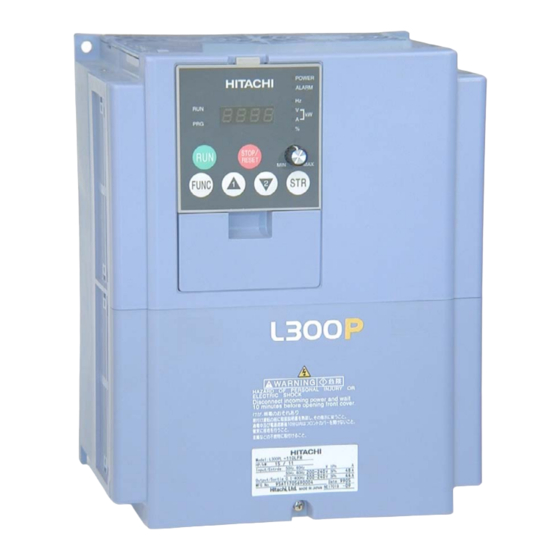
- Page 25 1–5 L300P Inverter Specifications The Hitachi L300P inverters have product specifi- cations labels located on the front and the right Label and Agency side of the housing, as pictured to the right. Be Approvals sure to verify that the specifications on the labels match your power source, motor, and application safety requirements.
-
Page 26: L300P Inverter Specifications
1–6 L300P Inverter Specifications L300P Inverter Specifications Tables for 200V Note that “General Specifications” on page 1–9 covers all L300P inverters, followed by class inverters footnotes for all specifications tables. Seven 200V models in the tables below (2 to 20 hp) have internal dynamic braking units (see “Dynamic Braking”... - Page 27 1–7 L300P Inverter Item 200V Class Specifications, continued L300P, 200V models, U.S. version 370LFU2 450LFU2 550LFU2 750LFU2 Applicable motor size *2 Rated capacity (200/240V) kVA 48.4 / 58.1 58.5 / 70.2 72.7 / 87.2 93.5 / 112.2 Rated input voltage 3-phase: 200 to 240V ±10%, 50/60 Hz ±5% Rated input current (A) Rated output voltage *3...
- Page 28 1–8 L300P Inverter Specifications Item 400V Class Specifications L300P inverters, U.S. version 110HFU2 150HFU2 185HFU2 220HFU2 300HFU2 370HFU2 400V models European ver. 110HFE2 150HFE2 185HFE2 220HFE2 300HFE2 370HFE2 Applicable motor size *2 18.5 Rated capacity (400 / 480V) kVA 15.2 / 18.2 20.0 / 24.1 25.6 / 30.7 29.7 / 35.7 39.4 / 47.3 48.4 / 58.1 Rated input voltage 3-phase (3-wire) 380 to 480V ±10%, 50/60 Hz ±5% Rated input current (A)
-
Page 29: Specifications
1–9 L300P Inverter General The following table (continued on next page) applies to all L300P inverter models. Specifications Item General Specifications Protective enclosure *1 *11 Models L300P–015xxx to 750xxx: IP20 (NEMA 1) Models L300P–900xx to 1320xxx: IP00 Control method Line-to-line sine wave pulse-width modulation (PWM) control Output frequency range *4 0.1 to 400 Hz Frequency accuracy... - Page 30 1–10 L300P Inverter Specifications Item General Specifications Protective functions Over-current, overload, braking resistor overload, over-voltage, EEPROM error, under- voltage error, CT (current transformer) error, CPU error, external trip, USP error, ground fault, input over-voltage, instantaneous power failure, inverter thermal trip, phase failure detection, IGBT error, thermistor error, expansion card 1 error, expansion card 2 error, under-voltage waiting error Environ-...
- Page 31 Footnotes for the preceding tables: Note 1: The protection method conforms to JEM 1030. Note 2: The applicable motor refers to Hitachi standard 3-phase motor (4-pole). When using other motors, care must be taken to prevent the rated motor current (50/60 Hz) from exceeding the rated output current of the inverter.
- Page 32 1–12 L300P Inverter Specifications Derating Curves The maximum available inverter current output is limited by the carrier frequency and ambient temperature. The carrier frequency is the inverter’s internal power switching frequency, settable from 0.5 kHz to 12 kHz, or 0.5 kHz to 8 kHz for higher horsepower models. Choosing a higher carrier frequency tends to decrease audible noise, but it also increases the internal heating of the inverter, thus decreasing (derating) the maximum current output capability.
- Page 33 1–13 L300P Inverter Derating curves, continued... L300P 30 to 37 kW 200V class 100% 370L 370L 300L 300L Carrier Frequency (kHz) L300P 45 to 75 kW 200V class 100% 750L 450L 550L 450L 550L 750L 550L 750L Carrier Frequency (kHz)
- Page 34 1–14 L300P Inverter Specifications Derating curves, continued... L300P 1.5 to 22 kW 400V class 015H, 022H, 030H, 040H, 055H, 075H, 110H, 150H, 185H, 220H 185H, 220H 150H 110H Carrier Frequency (kHz) L300P 30 to 37 kW 400V class 300H 370H 370H 300H Carrier Frequency (kHz)
- Page 35 1–15 L300P Inverter Derating curves, continued... L300P 45 to 75 kW 400V class 450H, 550H 450H 550H 750H 750H Carrier Frequency (kHz) L300P 90 to 132 kW 400V class 100% 900H 900H 1100H, 1320H 1100H, 1320H Carrier Frequency (kHz)
-
Page 36: Introduction To Variable-Frequency Drives
Introduction to Variable-Frequency Drives Introduction to Variable-Frequency Drives The Purpose of Hitachi inverters provide accurate speed control for 3-phase AC induction motors. You connect Motor Speed AC power to the inverter, and connect the inverter to the motor. Many applications can benefit... - Page 37 The Hitachi inverter is a rugged and reliable device. The intention is for the inverter to assume the role of controlling power to the motor during all normal operations. Therefore, this manual instructs you not to switch OFF power to the inverter while the motor is running (unless it is an emergency stop).
- Page 38 Braking” on page 5–6 for more information). For loads that continuously overhaul the motor for extended periods of time, the L300P may not be suitable (contact your Hitachi distributor). The inverter parameters include acceleration and deceleration, which you can set to match the needs of the application.
- Page 39 1–19 L300P Inverter Acceleration and deceleration settings specify the time required to go from a stop to maximum frequency (or visa versa). The Maximum speed Speed resulting slope (speed change divided by time) is the acceleration or deceleration. An increase in output frequency uses the accel- eration slope, while a decrease uses the deceleration slope.
-
Page 40: Frequently Asked Questions
1–20 Frequently Asked Questions Frequently Asked Questions What is the main advantage in using an inverter to drive a motor, compared to alternative solutions? A. An inverter can vary the motor speed with very little energy loss, unlike mechanical or hydraulic speed control solutions. The resulting energy savings can often pay for the inverter in a relatively short time. - Page 41 How many poles should the motor have? A. Hitachi inverters can be configured to operate motors with 2, 4, 6, or 8 poles. The greater the number of poles, the slower the top motor speed will be, but it will have higher torque at the base speed.
- Page 43 Inverter Mounting and Installation In This Chapter..page — Orientation to Inverter Features ............— Basic System Description ..............— Step-by-Step Basic Installation ............— Powerup Test .................. — Using the Front Panel Keypad ............
-
Page 44: Orientation To Inverter Features
2–2 Orientation to Inverter Features Orientation to Inverter Features Unpacking and Please take a few moments to unpack your new L300P inverter and perform these steps: Inspection 1. Look for any damage that may have occurred during shipping. 2. Verify the contents of the box include: a. - Page 45 2–3 L300P Inverter 2. Second-level access - First, ensure no Press here and slide cover downward power source of any kind is connected to the inverter. If power has been connected, wait five minutes after powerdown and verify the Charge Lamp indicator is OFF to proceed.
- Page 46 2–4 Orientation to Inverter Features 3. Third-level access - The L300P Latch to release digital operator provides for field installation of interface circuits. These circuits are on expansion cards, to be installed in the expansion bay. To access the expansion bay, you will need to remove the upper front panel.
-
Page 47: Basic System Description
2–5 L300P Inverter Basic System Description A motor control system will obviously include a motor and inverter, as well as a breaker or fuses for safety. If you are connecting a motor to the inverter on a test bench just to get started, that’s all you may need for now. -
Page 48: Step-By-Step Basic Installation
2–6 Step-by-Step Basic Installation Step-by-Step Basic Installation This section will guide you through the following basic steps of installation: 1. Study the warnings associated with mounting the inverter. 2. Select a suitable mounting location. NOTE: If the installation is in an EU country, study the EMC installation guidelines in Appendix D. - Page 49 2–7 L300P Inverter Step 2: To summarize the caution messages—you will need to find a solid, non-flammable, vertical surface that is in a relatively clean and dry environment. In order to ensure enough room for air circulation around the inverter to aid in cooling, maintain the specified clearance Ensure Adequate around the inverter specified in the diagram.
-
Page 50: Lfu2
2–8 Step-by-Step Basic Installation Step 4: Locate the applicable drawing on the following pages for your inverter. Dimensions are given in millimeters (inches) format. Smaller models come equipped with NEMA1 adapter (conduit box) for wire entry for U.S. models (LFU and HFU). The NEMA 1 Check Inverter adapter is optional for larger models as indicated in the drawings. - Page 51 2–9 L300P Inverter Exhaust 250(9.84) 2 - φ 7(0.28) 229(9.02) 10.5(0.41) Model L300P -185LFU2 -185HFU2, HFE2 -220LFU2 -220HFU2, HFE2 -300LFU2 -300HFU2, HFE2 Air intake 7(0.28) 229(9.02) 10.5(0.41) 104(4.09) 3 - φ 44(1.73) 204(8.03) 23(0.91) Wiring hole (knockout) Conduit box 244(9.61) 310(12.20) Model 22.5(0.89)
- Page 52 2–10 Step-by-Step Basic Installation Dimensional drawings, continued... 390(15.35) Exhaust 2 - φ 12(0.47) 45(1.77) 300(11.81) Model L300P -450LFU2 -450HFU2, HFE2 -550LFU2 -550HFU2, HFE2 -750HFU2, HFE2 2 - 12(0.47) 300(11.81) 45(1.77) 387(15.23) 1.5(0.06) Air intake 90(3.54) Optional adapter for NEMA1 rating 2 - φ...
- Page 53 2–11 L300P Inverter Dimensional drawings, continued... Exhaust 2 - φ 12(0.47) Model L300P -900HFU2, HFE2 -1100HFU2, HFE2 2 - 12(0.47) 300(11.81) Air intake 390(15.34) 90(3.54) Optional adapter for NEMA1 rating...
- Page 54 2–12 Step-by-Step Basic Installation Dimensional drawings, continued... 2 - φ 12(0.47) Exhaust Model L300P -1320HFU2,HFE2 2 - 12(0.47) 380(14.96) 480(18.90) Air intake 104(4.09) Optional adapter for NEMA1 rating...
- Page 55 2–13 L300P Inverter Step 5: The wiring enters the inverter through the entry/exit plate as shown to the right. The rubber grommets have a solid, thin membrane, Prepare for so that unused ones continue to seal the opening. Wiring To create an opening, use a sharp knife and carefully cut an “X”...
- Page 56 (GFI—ground fault interrupter) are slightly higher than fuse ratings to allow for nominal surges without tripping. • The chassis ground columns list the Hitachi-recommended AWG and the minimal AWG for UL conformity. • The optional external braking resistor wiring only applies to a few models that have a built- in braking unit.
- Page 57 2–15 L300P Inverter The following table lists wire and fuse sizes for 400V models. Wiring *1 Motor Output Brake Res. Power Lines *3 Chassis Ground 400V Inverter Fuse Models, (UL- Breaker AWG, AWG, L300P rated, ( GFI *1, *3 rec. class J, type) *2 600V)
- Page 58 2–16 Step-by-Step Basic Installation Terminal The following tables list the screw size of terminal and recommended torque for tightening for each of the L300P inverter models (400V models are on the next page). Dimensions and Torque Specs CAUTION: Fasten the screws with the specified fastening torque in the table below. Check for any loosening of screws.
- Page 59 2–17 L300P Inverter Terminal dimensions and torque specs, continued... Motor 400V Length Ring Lug Connector *1 Torque Output Inverter Input Screw size Voltage Models, power of terminal (AWG–bolt) ft-lbs wiring –bolt) L300P –015HFU2, HFE2 — 20–10 2–4 –022HFU2, HFE2 — 18–10 2–4 –040HFU2, HFE2...
- Page 60 2–18 Step-by-Step Basic Installation Step 6: In this step, you will connect wiring to the input of the inverter. All models have the same power connector terminals labeled R(L1), Wire the Inverter S(L2), and T(L3) for three-phase input. The Input to a Supply three phases may be connected in any order, as they are isolated from chassis ground and do not determine motor direction of rotation.
- Page 61 2–19 L300P Inverter NOTE: An inverter powered by a portable or emergency diesel power generator may result in a distorted power waveform, overheating the generator. In general, the generator capacity should be at least five times that of the inverter (kVA). CAUTION: Be sure that the input voltage matches the inverter specifications: •...
- Page 62 2–20 Step-by-Step Basic Installation Step 7: The process of motor selection is beyond the scope of this manual. However, it must be a three-phase AC induction motor. It should also come with a chassis ground lug. If the motor does not have three power input leads, stop the installation and verify the motor type. Other Wire the Inverter guidelines for wiring the motor include: Output to Motor...
-
Page 63: Powerup Test
3. Give a brief introduction to the use of the built-in operator keypad. The powerup test gives you an important starting point to ensure a safe and successful applica- tion of the Hitachi inverter. We highly recommend performing this test before proceeding to the other chapters in this manual. - Page 64 2–22 Powerup Test CAUTION: If you operate a motor at a frequency higher than the inverter standard default setting (50Hz/60Hz), be sure to check the motor and machine specifications with the respective manufacturer. Only operate the motor at elevated frequencies after getting their approval. Otherwise, there is the danger of equipment damage and/or injury to personnel.
-
Page 65: Using The Front Panel Keypad
Please take a moment to familiarize yourself with the keypad layout shown in the figure below. Introduction Parameter Display Power LED Alarm LED Run/Stop LED POWER HITACHI Display Units LEDs ALARM Hertz Program/Monitor LED 5 0.0 Volts or Amperes (kW = both ON) - Page 66 Using the Front Panel Keypad • Function Key – This key is used to navigate through the lists of parameters and functions POWER for setting and monitoring parameter values. HITACHI ALARM • Up/Down ( ) Keys – Use these 5 0.0...
- Page 67 2–25 L300P Inverter Keypad The L300P Series inverter drives have many programmable functions and parameters. Chapter 3 will cover these in detail, but you need to access just a few items to perform the Navigational Map powerup test. The menu structure makes use of function codes and parameter codes to allow programming and monitoring with only a 4-digit display and a few keys and LEDs.
- Page 68 2–26 Using the Front Panel Keypad Selecting In order to run the motor for the powerup test, this section will show how to: Functions and • select the inverter’s maximum output frequency to the motor Editing Parame- • select the keypad potentiometer as the source of motor speed command ters •...
- Page 69 2–27 L300P Inverter Select the Potentiometer for Speed Command - The motor speed may be controlled from the following sources: • Potentiometer on front panel keypad (if present) • Control terminals • Remote panel Then follow the steps in the table below to select the potentiometer for the speed command (the table resumes action from the end of the previous table).
- Page 70 2–28 Using the Front Panel Keypad Configure the Inverter for the Number of Motor Poles- The number of magnetic poles of a motor is determined by the motor’s internal winding arrangement. The specifications label on the motor usually indicates its number of poles. For proper operation, verify the parameter setting matches the motor poles.
- Page 71 L300P Inverter Monitoring After using the keypad for parameter editing, it’s a good idea to switch the Parameters with POWER HITACHI inverter from Program Mode to Monitor ALARM the Display Mode. This will turn out the PRG LED, and 5 0.0 the Hertz, Volt, Ampere, or % LED indicates the display units.
- Page 72 NOTE: Some factory automation devices such as PLCs have alternate Run/Program modes; the device is in either one mode or the other. In the Hitachi inverter, however, Run Mode alter- nates with Stop Mode, and Program Mode alternates with Monitor Mode. This arrangement lets you program some values while the inverter is operating—providing flexibility for mainte-...
- Page 73 Configuring Drive Parameters In This Chapter..page — Choosing a Programming Device ............. — Using Keypad Devices..............— “D” Group: Monitoring Functions ............— “F” Group: Main Profile Parameters..........— “A” Group: Standard Functions ............— “B” Group: Fine-Tuning Functions ..........
-
Page 74: Choosing A Programming Device
Choosing a Programming Device Introduction Hitachi variable frequency drives (inverters) use the latest electronics technology for getting the right AC waveform to the motor at the right time. The benefits are many, including energy savings and higher machine output or productivity. The flexibility required to handle a broad range of applications has required ever more configurable options and parameters—inverters... -
Page 75: Using Keypad Devices
The keypad layout (OPE–SRE) is shown below. All other program- ming devices for the inverter have a similar key arrangement and function. Parameter Display Power LED Alarm LED Run/Stop LED POWER HITACHI Display Units LEDs ALARM Hertz Program/Monitor LED 5 0.0 Volts or Amperes... - Page 76 3–4 Using Keypad Devices Keypad Whether you use the keypad on the inverter or the read-write copy unit, each navigates the same way. The diagram below shows the basic navigational map of parameters and functions. Navigational Map Monitor Mode Program Mode Select Function Select Parameter Edit Parameter...
- Page 77 3–5 L300P Inverter Operational The RUN and PGM LEDs tell just part of the story; Run Mode and Program Modes are independent Modes STOP RESET modes, not opposite modes. In the state diagram to Stop the right, Run alternates with Stop, and Program Mode alternates with Monitor Mode.
-
Page 78: D" Group: Monitoring Functions
3–6 “D” Group: Monitoring Functions “D” Group: Monitoring Functions Parameter You can access important system parameter values with the “D” Group monitoring functions, Monitoring whether the inverter is in Run Mode or Stop Mode. After selecting the function code number for the parameter you want to monitor, press the Function key once to show the value on the Functions display. - Page 79 3–7 L300P Inverter “D” Function Range Mode SRW Display Func. and Units Name Description Edit Code D016 Cumulative operation Displays total time the inverter has — hours 0000000hr RUN time monitor been in RUN mode in hours. Range is 0 to 9999 / 1000 to 9999/ 100 to 999 (10,000 to 99,900) hrs.
-
Page 80: F" Group: Main Profile Parameters
3–8 “F” Group: Main Profile Parameters “F” Group: Main Profile Parameters The basic frequency (speed) profile is defined by parameters contained in the Output “F” Group as shown to the right. The F002 F003 frequency output frequency is set in Hz, but accel- eration and deceleration are specified F001 seconds (the time to ramp from zero to... -
Page 81: A" Group: Standard Functions
3–9 L300P Inverter “A” Group: Standard Functions Basic Parameter These settings affect the most fundamental behavior of the inverter—the outputs to the motor. Settings The frequency of the inverter’s AC output determines the motor speed. You may select from three different sources for the reference speed. During application development you may prefer using the potentiometer, but you may switch to an external source (control terminal setting) in the finished application, for example. - Page 82 3–10 “A” Group: Standard Functions “A” Function Defaults Mode SRW Display Units Edit Func. –FE2 –FU2 –FR Name Description Lo Hi Code (EU) (US) (JP) ✘ ✘ A203 Base frequency setting, Settable from 30 Hz to the >A203 2F-BASE 0060Hz 2nd motor maximum frequency ✘...
- Page 83 3–11 L300P Inverter Analog Input The inverter has the capability to accept external analog inputs that can command the output frequency to the motor. Signals including voltage input (0 to +10V) at terminal [O], bipolar Settings input (-10 to +10V) at terminal [O2], and current input (4 to 20mA) at terminal [OI] are avail- able.
- Page 84 3–12 “A” Group: Standard Functions “A” Function Defaults Mode SRW Display Units Edit Func. –FE2 –FU2 –FR Name Description Lo Hi Code (EU) (US) (JP) ✘ ✘ A005 [AT] selection Two options; select codes: — >A005 AT SELECT O/OI 00 Select between [O] and [OI] at [AT] 01 Select between [O] and [O2] at [AT]...
- Page 85 3–13 L300P Inverter Multi-speed and The L300P inverter has the capability to store and output up to 16 preset frequencies to the motor (A020 to A035). As in traditional motion terminology, we call this multi-speed profile Jog Frequency capability. These preset frequencies are selected by means of digital inputs to the inverter. The Settings inverter applies the current acceleration or deceleration setting to change from the current output frequency to the new one.
- Page 86 3–14 “A” Group: Standard Functions Torque Control The inverter generates the motor output Inverter Torque Control Algorithms according to the V/f algorithm. Parameter Algorithms A044 A044 selects the inverter torque control V/f control, algorithm for generating the frequency constant torque output, as shown in the diagram to the right (A244 for 2nd motor).
- Page 87 3–15 L300P Inverter Using parameter A045 you can modify the voltage gain of the inverter. This is specified as a percentage of the full-scale setting AVR (Automatic Voltage Regulation) in parameter A082. The gain can be set from 20% to 100%. It must be adjusted in accordance with the motor speci- fications.
- Page 88 3–16 “A” Group: Standard Functions The V/f free-setting endpoint f7/V7 Output voltage parameters must stay within the more basic inverter limits in order for the Voltage to output or AVR voltage specified free-setting characteristic curve to be achieved. For example, the inverter cannot output a higher voltage than the input voltage or the AVR setting voltage (Automatic Voltage...
- Page 89 3–17 L300P Inverter DC Braking The DC braking feature can provide additional stopping torque when compared to a normal deceleration to a stop. It can also ensure the motor and load are stopped before acceleration. Settings When decelerating – DC braking is Output particularly useful at low speeds when voltage...
- Page 90 3–18 “A” Group: Standard Functions “A” Function Defaults Mode SRW Display Units Edit Func. –FE2 –FU2 –FR Name Description Lo Hi Code (EU) (US) (JP) ✘ ✔ A051 DC braking enable Two options; select codes: — >A051 DCB Mode 00 Disable 01 Enable ✘...
- Page 91 3–19 L300P Inverter Frequency- Frequency Limits – Upper and lower limits can be imposed on the inverter related Functions Output frequency output frequency. These limits will apply Upper regardless of the source of the speed A061 limit reference. You can configure the lower frequency limit to be greater than zero as Settable shown in the graph to the right.
- Page 92 3–20 “A” Group: Standard Functions “A” Function Defaults Mode SRW Display Units Edit Func. –FE2 –FU2 –FR Name Description Lo Hi Code (EU) (US) (JP) ✘ ✔ A063 Jump (center) frequency Up to 3 output frequencies 0.00 0.00 0.00 >A063 JUMP 0000.00Hz A065 setting...
- Page 93 3–21 L300P Inverter PID Control When enabled, the built-in PID loop calculates an ideal inverter output value to cause a loop feedback process variable (PV) to move closer in value to the setpoint (SP). The current frequency command serves as the SP. The PID loop algorithm will read the analog input for the process variable (you specify either current or voltage input) and calculate the output.
- Page 94 3–22 “A” Group: Standard Functions Automatic The automatic voltage regulation (AVR) feature keeps the inverter output voltage at a relatively constant amplitude during power input fluctuations. This can be useful if the installa- Voltage tion is subject to input voltage disturbances. However, the inverter cannot boost its motor Regulation (AVR) output to a voltage higher than the power input voltage.
- Page 95 3–23 L300P Inverter Second The L300P inverter features two-stage acceleration and deceleration ramps. This gives flexibil- ity in the profile shape. You can specify the frequency transition point, the point at which the Acceleration and standard acceleration (F002) or deceleration (F003) changes to the second acceleration (A092) Deceleration or deceleration (A093).
- Page 96 3–24 “A” Group: Standard Functions “A” Function Defaults Mode SRW Display Units Edit Func. –FE2 –FU2 –FR Name Description Lo Hi Code (EU) (US) (JP) ✘ ✘ A096 Dec1 to Dec2 frequency Output frequency at which >A096 DECEL CHFr 0000.00Hz transition point Decel1 switches to Decel2, range is 0.00 to 400.0 Hz...
- Page 97 3–25 L300P Inverter Accel/Decel Standard (default) acceleration and deceleration is linear with time. The inverter CPU can also calculate other curves shown in the graphs below. The sigmoid, U-shape, and reverse U-shape Characteristics curves are useful for favoring the load characteristics in particular applications. Curve settings for acceleration and deceleration are independently selected parameters A097 and A098 respectively.
- Page 98 3–26 “A” Group: Standard Functions The acceleration and deceleration curves can deviate from a straight line to a varying degree. Parameters A131 and A132 control the amount of deviation for the acceleration and decelera- tion curves respectively. The following graphs show intermediate output frequency points as a percentage of the target frequency, for 25%, 50%, and 75% acceleration time intervals.
- Page 99 3–27 L300P Inverter Additional The parameters in the following table adjust the input characteristics of the analog inputs. When using the inputs to command the inverter output frequency, these parameters adjust the Analog Input starting and ending ranges for the voltage or current, as well as the output frequency range. Settings Related characteristic diagrams are located in “Analog Input Settings”...
-
Page 100: B" Group: Fine-Tuning Functions
3–28 “B” Group: Fine-Tuning Functions “B” Group: Fine-Tuning Functions The “B” Group of functions and parameters adjust some of the more subtle but useful aspects of motor control and system configuration. Automatic The restart mode determines how the inverter will resume operation after a fault causes a trip Restart Mode and event. - Page 101 3–29 L300P Inverter “B” Function Defaults Mode SRW Display Units Edit Func. –FE2 –FU2 –FR Name Description Lo Hi Code (EU) (US) (JP) ✘ ✔ B002 Allowable under- The amount of time a power sec. >b002 IPS TIME 1.0s voltage power failure input under-voltage can time occur without tripping the...
- Page 102 3–30 “B” Group: Fine-Tuning Functions The torque developed in a motor is directly proportional to the current in the windings, which is also proportional to the heat generated (and temperature, over time). Therefore, you must set the thermal overload threshold in terms of current (amperes) with parameter B012. The range is 50% to 120% of the rated current for each inverter model.
- Page 103 3–31 L300P Inverter Constant Torque Characteristic – The left graph below shows the effect of the constant torque characteristic curve. For example, at 2.5Hz, the output current level to cause overheating in a fixed time period is reduced by a factor of 0.9. The right graph below shows the reduced trip current levels in those conditions for given trip times.
- Page 104 3–32 “B” Group: Fine-Tuning Functions Suppose the electronic thermal setting (B012) is set to 44 Amperes. The left graph below shows the effect of the free setting torque characteristic curve. For example, at (B017) Hz, the output current level to cause overheating in a fixed time period is reduced by a factor of (B018). The right graph below shows the reduced trip current levels in those conditions for given trip times.
- Page 105 3–33 L300P Inverter Overload If the inverter’s output current exceeds a restriction area preset current level you specify during Restriction Motor B022 acceleration or constant speed, the Current overload restriction feature automati- cally reduces the output frequency to restrict the overload. This feature does not generate an alarm or trip event.
- Page 106 3–34 “B” Group: Fine-Tuning Functions “B” Function Defaults Mode SRW Display Units Edit Func. –FE2 –FU2 –FR Name Description Lo Hi Code (EU) (US) (JP) ✘ ✔ B026 Deceleration rate at Sets the deceleration rate (2) 1.00 1.00 1.00 sec. >b026 OLOAD 2CONST 01.00...
- Page 107 3–35 L300P Inverter Software Lock The software lock function keeps personnel from accidentally changing parameters in the inverter memory. Use B031 to select from various protection levels. Mode The table below lists all combinations of B031 option codes and the ON/OFF state of the [SFT] input.
- Page 108 3–36 “B” Group: Fine-Tuning Functions Miscellaneous The miscellaneous settings include scaling factors, initialization modes, and others. This section covers some of the most important settings you may need to configure. Settings “B” Function Defaults Mode SRW Display Units Edit Func. –FE2 –FU2 –FR...
- Page 109 3–37 L300P Inverter For example, you can set B037=01 to have the inverter suppress the displaying of all analog input parameters when A001=01, as shown in the first row of the following table. Function Resulting Non-displayed Data Notes Code Functions (when B37 = 01) A001 A005, A006, A011 –...
- Page 110 3–38 “B” Group: Fine-Tuning Functions Miscellaneous functions, continued... B083: Carrier frequency adjustment – The internal switching frequency of the inverter circuitry (also called the chopper frequency). It is called the carrier frequency because the lower AC output frequency of the inverter “rides” the carrier. The faint, high-pitched sound you hear when the inverter is in Run Mode is characteristic of switching power supplies in general.
- Page 111 3–39 L300P Inverter “B” Function Defaults Mode SRW Display Units Edit Func. –FE2 –FU2 –FR Name Description Lo Hi Code (EU) (US) (JP) ✘ ✘ B085 Country code for initial- Select default parameter — >b085 INITIAL SELECT ization values for country on initial- ization, four option codes: 00 Japan version 01 Europe version...
- Page 112 3–40 “B” Group: Fine-Tuning Functions Miscellaneous functions, continued... B091/B088: Stop Mode / Restart Mode Configuration – You can configure how the inverter performs a standard stop (each time Run FWD and REV signals turn OFF). Setting B091 deter- mines whether the inverter will control the deceleration, or whether it will perform a free-run stop (coast to a stop).
- Page 113 3–41 L300P Inverter “B” Function Defaults Mode SRW Display Units Edit Func. –FE2 –FU2 –FR Name Description Lo Hi Code (EU) (US) (JP) ✘ ✔ B090 Dynamic braking usage Selects the braking duty — >b090 BRD 000.0% ratio cycle for the dynamic braking resistor (total brake % ON-time per 100 sec.
- Page 114 3–42 “B” Group: Fine-Tuning Functions Free-setting The free-setting V/f inverter mode of operation uses voltage and frequency parameter pairs to define seven points on a V/f graph. This provides a way to define a multi-segment V/f curve V/f Pattern that best suits your application. The frequency settings do require that F1 ≤...
-
Page 115: C" Group: Intelligent Terminal Functions
3–43 L300P Inverter “C” Group: Intelligent Terminal Functions The five input terminals [1], [2], [3], [4], and [5] can be configured for any of 33 different functions (34 functions for –xFE2/–xFU2 models). The next two tables show how to configure the five terminals. - Page 116 3–44 “C” Group: Intelligent Terminal Functions The input logic convention is programmable for each of the six inputs. Most inputs default to normally open (active high), but you can select normally closed (active low) in order to invert the sense of the logic. “C”...
- Page 117 3–45 L300P Inverter Intelligent Input Each of the five intelligent terminals may be assigned any of the options in the following table. When you program one of the option codes for terminal assignments C001 to C005, the respec- Terminal tive terminal assumes the function role of that option code. The terminal functions have a Overview symbol or abbreviation that we use to label a terminal using that function.
- Page 118 3–46 “C” Group: Intelligent Terminal Functions Input Function Summary Table Option Terminal Function Name Description Code Symbol Unattended Start ON powerup, the inverter will not resume a Run Protection command (mostly used in the US) ON powerup, the inverter will resume a RUN command that was active before power loss Commercial Power OFF-to-ON transition signals the inverter that the...
- Page 119 3–47 L300P Inverter Input Function Summary Table Option Terminal Function Name Description Code Symbol Remote Control Decelerates (decreases output frequency) motor from DOWN Function current frequency (motorized speed pot.) No change to output frequency Remote Control Data Clears the UP/DWN frequency memory by forcing it Clearing to equal the set frequency parameter F001.
- Page 120 3–48 “C” Group: Intelligent Terminal Functions Output Terminal The inverter provides configuration for logic (discrete) and analog outputs, shown in the table below. Configuration “C” Function Defaults Mode SRW Display Units Edit Func. –FE2 –FU2 –FR Name Description Lo Hi Code (EU) (US)
- Page 121 3–49 L300P Inverter Output Summary Table - This table shows all 12 functions (13 for –xFU2 models) for the logic outputs terminals [11] and [12] at a glance. Detailed function descriptions, related param- eters and settings, and example wiring diagrams are in “Using Intelligent Output Terminals”...
- Page 122 3–50 “C” Group: Intelligent Terminal Functions Output Function Summary Table Option Terminal Function Name Description Code Symbol Thermal alarm signal when the thermal limit for the motor is exceeded when the thermal limit is not exceeded Run command source when the Run command source is the operator keypad monitor (A002=02) (–xFU2 and –xFE2...
- Page 123 3–51 L300P Inverter Output Function The following parameters work in C041 conjunction with the intelligent output Adjustment Motor function, when configured. The current Parameters overload level parameter (C041) sets the motor current level at which the overload signal [OL] turns ON. The range of settings is from 0% to 200% of Overload the rated current for the inverter.
- Page 124 3–52 “C” Group: Intelligent Terminal Functions “C” Function Defaults Mode SRW Display Units Edit Func. –FE2 –FU2 –FR Name Description Lo Hi Code (EU) (US) (JP) ✘ ✔ C044 PID deviation level Sets the PID loop error >C044 PID LEVEL 003.0% setting threshold |SP - PV|...
- Page 125 3–53 L300P Inverter Serial The following table configures the communications port of the L300P inverter. You can have up to thirty-two devices on the serial communications network. The inverters are slaves and the Communications computer or digital operator is the master. Thus, all inverters on the serial connection must use the same baud rate, data length, parity, and stop bits.
- Page 126 3–54 “C” Group: Intelligent Terminal Functions Analog Signal The functions in the following table configure the signals for the analog output terminals. Note that these settings do not change the current/voltage or sink/source characteristics – only the Calibration zero and span (scaling) of the signals. Settings NOTE: See additional settings for analog calibration: Parameter B080 [AM] Terminal Analog Meter Adjustment (gain), parameter B081 [FM] Terminal Analog Meter Adjustment (gain).
- Page 127 3–55 L300P Inverter Miscellaneous The following table contains miscellaneous functions not in other function groups. Functions “C” Function Defaults Mode SRW Display Units Edit Func. –FE2 –FU2 –FR Name Description Lo Hi Code (EU) (US) (JP) ✘ ✔ C091 Debug mode enable Two option codes: —...
-
Page 128: H" Group: Motor Constants Functions
3–56 “H” Group: Motor Constants Functions “H” Group: Motor Constants Functions Introduction The “H” Group parameters configure the Inverter Torque Control Algorithms inverter for the motor characteristics. You A044 must manually set H003 and H004 values V/f control, to match the motor. The remaining H206 constant torque parameters are factory-set. -
Page 129: P" Group: Expansion Card Functions
3–57 L300P Inverter “P” Group: Expansion Card Functions The two (optional) expansion cards for the L300P have associated configuration data. The following table defines the functions and their value ranges. Please refer to the expansion card manual for more details. “P”... - Page 130 3–58 “P” Group: Expansion Card Functions Miscellaneous The following table contains miscellaneous function(s) not in other function groups. Note that P050 is only available on –xFE2/–xFU2 models. Functions “P” Function Defaults Mode SRW Display Units Edit Func. –FE2 –FU2 –FR Name Description Lo Hi...
-
Page 131: U" Group: User-Selectable Menu Functions
3–59 L300P Inverter “U” Group: User-selectable Menu Functions The user-selectable menu functions allow you to configure (select) any twelve of the other functions in the inverter and place them together in a convenient list. This feature provides quick access for the most-used functions needed for your application. Each U Group function can serve as a pointer to any of the other parameters. -
Page 132: Programming Error Codes
3–60 Programming Error Codes Programming Error Codes The L300P inverter operator keypad displays a special code (begins with the character) to indicate a programming error. Programming errors exist when one parameter conflicts with the meaningful range permitted by related parameter(s). Note that particular real-time frequency (speed) input levels can cause a conflict in some situations. - Page 133 3–61 L300P Inverter Parameter out of bounds Boundary defined by... Programming Error Code Code Description <, > Code Description 091 291 A061 / A261 Frequency upper limit > B112 Free-setting V/f frequency (7) setting; 1st, 2nd motor 092 292 A062 / A262 Frequency lower limit >...
- Page 135 Operations and Monitoring In This Chapter..page — Introduction ..................— Optional Alarm Output at Power Loss ..........— Connecting to PLCs and Other Devices ........... — Using Intelligent Input Terminals ............. — Using Intelligent Output Terminals ..........— Analog Input Operation..............
- Page 136 4–2 Introduction Introduction The previous material in Chapter 3 gave a reference listing of all the programmable functions of the inverter. We suggest that you first scan through the listing of inverter functions to gain a general familiarity. This chapter will build on that knowledge in the following ways: 1.
- Page 137 4–3 L300P Inverter Warnings for Before continuing, please read the following Warning messages. Operating Procedures WARNING: Be sure to turn ON the input power supply only after closing the front case. While the inverter is energized, be sure not to open the front case. Otherwise, there is the danger of electric shock.
-
Page 138: Optional Alarm Output At Power Loss
4–4 Optional Alarm Output at Power Loss Optional Alarm Output at Power Loss With the default L300P inverter configuration, a sudden power loss will cause the inverter to shut down immediately. If running at the time, the motor and load will coast to a stop. And without power, the inverter’s alarm output will not activate. - Page 139 4–5 L300P Inverter Follow the steps to implement the wiring change shown in the previous diagram. 1. Remove the 2-wire jumper J51 (terminals [R0] and [T0] to connector J51). 2. Procure several inches of multi-strand 20 AWG (0.5mm ) or slightly heavier wire. 3.
-
Page 140: Connecting To Plcs And Other Devices
Connecting to PLCs and Other Devices Connecting to PLCs and Other Devices Hitachi inverters (drives) are useful in many types of applications. During installation, the inverter keypad (or other programming device) will facilitate the initial configuration. After installation, the inverter will generally receive its control commands through the control logic terminals or serial interface from another controlling device. - Page 141 4–7 L300P Inverter Example Wiring The schematic diagram below provides a general example of logic connector wiring, in addition to basic power and motor wiring covered in Chapter 2. The goal of this chapter is to Diagram help you determine the proper connections for the various terminals shown below for your specific application needs.
- Page 142 4–8 Connecting to PLCs and Other Devices Specifications of The control logic connector board is removable for wiring convenience as shown below (first, remove two retaining screws). The small connector to the left is for serial communications. Control and Logic Connections Retaining screw locations Analog outputs...
- Page 143 4–9 L300P Inverter Terminal Name Description Ratings and Notes [AL0] Relay common contact Contacts AL0–AL1, maximum loads: 250VAC, 2A; 30VDC, 8A resistive load [AL1] Relay contact, normally 250VAC, 0.2A; 30VDC, 0.6A inductive load closed Contacts AL0–AL2, maximum loads: 250VAC, 1A; 30VDC 1A max. resistive load [AL2] Relay contact, normally 250VAC, 0.2A;...
-
Page 144: Using Intelligent Input Terminals
4–10 Using Intelligent Input Terminals Using Intelligent Input Terminals Intelligent terminals [1], [2], [3], [4] and [5] are identical, programmable inputs for general use. The input circuits can use the inverter’s internal (isolated) +24V field supply (P24) to power the inputs. - Page 145 4–11 L300P Inverter Wiring Diagram The input wiring diagrams in this chapter are examples only. Default and non-default input terminal assignments are noted throughout; your particular assignments may be different. The Conventions wiring diagrams show the –xFU2/–FR model default [P24]–[PLC] jumper position (U.S./Jpn versions), as shown below on the left.
- Page 146 4–12 Using Intelligent Input Terminals Multi-Speed The inverter can store up to 16 different fixed target frequencies (speeds) in parameters A020 to A035. Binary inputs select the speed through four of the intelligent terminals configured as Select binary-encoded inputs CF1 to CF4 per the table. These can be any of the five inputs, and in any order.
- Page 147 4–13 L300P Inverter Opt. Input Symbol Function Name Description Code State Binary speed select, Bit 0, logical 1 Bit 0 (LSB) Bit 0, logical 0 Binary speed select, Bit 1, logical 1 Bit 1 Bit 1, logical 0 Binary speed binary Bit 2, logical 1 select, Bit 2 Bit 2, logical 0...
- Page 148 4–14 Using Intelligent Input Terminals The Bit Operation method of speed control uses up to five intelligent inputs to select any of up to six speeds from a total of eight speeds. (At least two of the SF1–SF7 functions will be unused, since there are only five inputs.) Since the all-switches-OFF combination selects the first speed, you only need N-1 switches to select N speeds.
- Page 149 4–15 L300P Inverter Jogging The Jog input [JG] is used to command the motor to rotate slowly in small increments Command [JG] for manual operation. The speed is limited to 10 Hz. The frequency for the jogging [FW] operation is set by parameter A038. Jogging does not use an acceleration ramp.
- Page 150 4–16 Using Intelligent Input Terminals External Signal When the terminal [DB] is turned ON, the Scenario 1 DC braking [DB] feature is enabled. Set the for DC Injection following parameters when the external DC Braking [FW, RV] braking terminal is to be used: •...
- Page 151 4–17 L300P Inverter Set Second Motor If you assign the [SET] function to an intelligent input terminal, you can select between two sets of motor parameters. These second parameters store an alternate set of motor characteris- tics. When terminal [SET] is turned ON, the inverter will use the second set of parameters, generating the frequency output to the motor.
- Page 152 4–18 Using Intelligent Input Terminals Two-stage When terminal [2CH] is turned ON, the Output inverter changes the rate of acceleration and Acceleration and frequency target frequency deceleration from the initial settings (F002 Deceleration and F003) to use the second set of accelera- second tion/deceleration values.
- Page 153 4–19 L300P Inverter Free-run Stop When the terminal [FRS] is turned ON, the inverter turns OFF the output and the motor enters the free-run state (coasting). If terminal [FRS] is turned OFF, the output resumes sending power to the motor if the Run command is still active. The free-run stop feature works with other parameters to provide flexibility in stopping and starting motor rotation.
- Page 154 4–20 Using Intelligent Input Terminals External Trip When the terminal [EXT] is turned ON, the inverter enters the trip state, indicates error code E12, and stops the output. This is a general purpose interrupt type feature, and the meaning of the error depends on what you connect to the [EXT] terminal.
- Page 155 4–21 L300P Inverter Unattended Start If the Run command is already present when power is turned ON, the inverter starts running immediately after powerup. The Unattended Start Protection (USP) function prevents that Protection automatic startup, so that the inverter will not run without outside intervention. When USP is active, there are two ways to reset an alarm and resume running: 1.
- Page 156 4–22 Using Intelligent Input Terminals Commercial The commercial power source switching function is useful in systems with excessive starting torque requirements. This feature permits the motor to be started “across the line,” sometimes Power Source called a bypass configuration. After the motor is running, the inverter takes over to control the Switching speed.
- Page 157 4–23 L300P Inverter In the previous timing diagram, when the motor has been started across the line, Mg2 is switched OFF and Mg3 is switched ON. With the Forward command to the inverter already ON, the [CS] terminal is switched ON and relay Mg1 contacts close. The inverter will then read the motor RPM (frequency matching).
- Page 158 4–24 Using Intelligent Input Terminals Software Lock When the terminal [SFT] is turned ON, the data of all the parameters and functions (except the output frequency, depending on the setting of B031) is locked (prohibited from editing). When the data is locked, the keypad keys cannot edit inverter parameters. To edit parameters again, turn OFF the [SFT] terminal input.
- Page 159 4–25 L300P Inverter Analog Input The [AT] terminal operates in conjunction with parameter setting A005 to determine the analog input terminals that are enabled for current or voltage input. Setting A006 determines whether Current/Voltage the signal will be bipolar, allowing for a reverse direction range. Note that current input signal Select cannot be bipolar and cannot reverse direction (must use [FW] and [RV] command with current input operation).
- Page 160 4–26 Using Intelligent Input Terminals Reset Inverter The [RS] terminal causes the inverter to 12 ms execute the reset operation. If the inverter is minimum in Trip Mode, the reset cancels the Trip [RS] state. When the signal [RS] is turned ON approx.
- Page 161 4–27 L300P Inverter Thermistor Motors that are equipped with a thermistor can be protected from overheating. Input terminal [TH] is dedicated to sense a thermistor resistance. The input can be set up (via B098 and B099) Thermal to accept a wide variety of NTC or PTC type thermistors. Use this function to protect the motor Protection from overheating.
- Page 162 4–28 Using Intelligent Input Terminals Three-wire The 3-wire interface is an industry standard motor control interface. This function uses two inputs for momentary contact start/stop control, and a third for selecting forward or reverse Interface direction. To implement the 3-wire interface, assign 20 [STA] (Start), 21 [STP] (Stop), and 22 Operation [F/R] (Forward/Reverse) to three of the intelligent input terminals.
- Page 163 4–29 L300P Inverter PID ON/OFF The PID loop function is useful for controlling motor speed to achieve constant flow, pressure, temperature, etc. in many process applications. The PID Disable function temporarily suspends and PID Clear PID loop execution via an intelligent input terminal. It overrides the parameter A071 (PID Enable) to stop PID execution and return to normal motor frequency output characteristics.
- Page 164 4–30 Using Intelligent Input Terminals Remote Control The [UP] [DWN] terminal functions can adjust the output frequency for remote control while the motor is running. The acceleration time and deceleration time used with this function is the Up and Down same as for normal operation ACC1 and DEC1 (2ACC1,2DEC1).
- Page 165 4–31 L300P Inverter Force Operation This function permits a digital operator interface to override the Run command source setting (A002) when it is configured for a source other than the operator interface. When the [OPE] from Digital terminal is ON and the operator interface gives a Run command, the inverter uses the standard Operator output frequency settings to operate the motor.
- Page 166 4–32 Using Intelligent Input Terminals Overload The inverter constantly monitors the motor current during acceleration, deceleration, and constant speed. If the inverter reaches the overload restriction level, it adjusts the output Restriction frequency automatically to limit the amount of overload. This function prevents an over-current trip by inertia during rapid acceleration or large changes in load at constant speed.
- Page 167 4–33 L300P Inverter The figure below shows the operation during an overload restriction event. The overload restriction level is set by B022 and B025. The overload restriction constant is the time to decel- erate to 0Hz from maximum frequency. When this function operates, the acceleration time will be longer than the normal acceleration time.
- Page 168 4–34 Using Intelligent Input Terminals Run Enable for The Run Enable for FW/RV input provides a way to enable or disable the [FW] and [RV] input terminals in real time, including a Run command from an operator keypad. This is useful for FW/RV (–xFU2 applications that require a logic type safety interlock for FWD Run or REV Run commands.
-
Page 169: Using Intelligent Output Terminals
4–35 L300P Inverter Using Intelligent Output Terminals The intelligent relay terminals are programmable in a similar way to the intelligent input termi- nals. The inverter has several output functions that you can assign individually to the two intel- ligent relay outputs. They are normally open (type Form A). In addition to these relay outputs, the alarm relay output (type Form C) has normally open and normally closed contacts. - Page 170 4–36 Using Intelligent Output Terminals Run Signal When the [RUN] signal is selected as an intelligent output terminal, the inverter [FW, RV] outputs a signal on that terminal when it is Motor in Run Mode. The output relay contacts are speed closed when the inverter is in Run Mode start freq.
- Page 171 4–37 L300P Inverter Frequency Arrival The Frequency Arrival group of outputs help coordinate external systems with the current velocity profile of the inverter. As the name implies, output [FA1] turns ON when the output Signals frequency arrives at the standard set frequency (parameter F001). Outputs [FA2] through [FA5] provide variations on this function for increased flexibility, relying on two programmable accel/ decel thresholds.
- Page 172 4–38 Using Intelligent Output Terminals Frequency arrival output [FA1] uses the Output standard output frequency (parameter F001) frequency as the threshold for switching. In the figure to the right, the inverter accelerates to the set output frequency, which serves as the Threshold threshold for [FA1].
- Page 173 4–39 L300P Inverter Overload When the output current exceeds a Current threshold preset value, the [OL] or [OL2] Advance Notice terminal signal turns ON. The parame- power running Signal C041 ter C041 (or C111, respectively) sets value the overload threshold. The overload C041 regeneration detection circuit operates during...
- Page 174 4–40 Using Intelligent Output Terminals Output Deviation The PID loop error is defined as the Error magnitude (absolute value) of the differ- for PID Control Process variable (SP-PV) ence between the Setpoint (target value) Setpoint and the Process Variable (actual value). C044 When the error magnitude exceeds the value...
- Page 175 4–41 L300P Inverter Alarm Signal The inverter alarm signal is active when a fault has occurred and it is in the Trip Mode (refer to the STOP RESET diagram at right). When the fault is cleared the Stop alarm signal becomes inactive. We must make a distinction between the alarm STOP signal AL and the alarm relay contacts [AL0],...
- Page 176 4–42 Using Intelligent Output Terminals The alarm output terminals operate as shown below (left) by default. The contact logic can be inverted as shown (below right) by using the parameter setting C036. The relay contacts normally open (N.O.) and normally closed (N.O.) convention uses “normal” to mean the inverter has power and is in Run or Stop Mode.
- Page 177 4–43 L300P Inverter Instantaneous An instantaneous power failure (complete loss) or under-voltage condition (partial loss) of inverter input voltage can occur without warning. L300P Series inverters can be configured to Power Failure / respond to these conditions in different ways. You can select whether the inverter trips or retries Under-voltage (restart attempt) when an instantaneous power failure or under-voltage condition occurs.
- Page 178 4–44 Using Intelligent Output Terminals Opt. Output Symbol Function Name Description Code State Instantaneous when the inverter detects a loss of input Power Failure power when the inverter has input power Under-voltage when the inverter input power is less than condition the specified input range when the inverter input power is within...
- Page 179 4–45 L300P Inverter Examples 3 and 4 relate to configuring the inverter to retry upon power failure. Frequency matching is possible if the inverter frequency is greater than the B007 value. Example 3: Motor resumes via frequency-matching Example 4: Motor restarts from 0Hz Power supply Power supply Inverter output...
- Page 180 4–46 Using Intelligent Output Terminals Run Time / L300P Series inverters accumulate the total hours in Run Mode (run time) and the total hours of power-ON time. You can set thresholds for these accumulating timers. Once the threshold is Power-On Time exceeded, an output terminal will turn ON.
- Page 181 4–47 L300P Inverter Thermal Warning The purpose of the electronic thermal setting is to protect the motor from overloading, overheating and being damaged. The setting is based on the rated motor current. The inverter Signal calculates the thermal rise (heating) of the motor using the current output to the motor squared, integrated over the time spent at those levels.
- Page 182 4–48 Using Intelligent Output Terminals Constant Torque Characteristic – The left graph below shows the effect of the constant torque characteristic curve. For example, at 2.5Hz, the output current level to cause overheating in a fixed time period is reduced by a factor of 0.9. The right graph below shows the reduced trip current levels in those conditions for given trip times.
- Page 183 4–49 L300P Inverter Suppose the electronic thermal setting (B012) is set to 44 Amperes. The graph below shows the effect of the free setting torque characteristic curve. For example, at (B017) Hz, the output current level to cause overheating in a fixed time period is reduced to (B018) A. Points (x), (y), and (z) show the adjusted trip current levels in those conditions for given trip times.
- Page 184 4–50 Using Intelligent Output Terminals Run Command The Run Command Source Monitor intelligent output provides a way to monitor the present setting for the Run Command Source Setting parameter (A002). Some applications use devices Source Monitor external to the inverter, such as intelligent keypads or network control hosts, which can change (–xFU2 models the A002 parameter setting at various times in normal operation.
-
Page 185: Analog Input Operation
4–51 L300P Inverter Analog Input Operation Input Terminal The L300P inverters provide for an external analog H O2 Signals input to command the inverter frequency output value. The analog input terminal group includes O OI the [L], [OI], [O], [O2], and [H] terminals on the A GND control connector, which provide for Voltage [O] +V Ref. - Page 186 4–52 Analog Input Operation The following tables show the available analog input settings. Parameters A006, A005, and input terminal [AT] determine the External Frequency Command input terminals that are avail- able and how they function. The Trim Frequency input [O2]—[L] is available (when check marked) for some settings.
- Page 187 4–53 L300P Inverter The examples below show how the use of the [AT] input during operation enables/disables the Trim Frequency Command input [O2]—[L]. The [O2]—[L] input may be used alone, or as an offset control for the primary analog input. Example 1: Without reverse Example 2: With reverse [FW] terminal...
-
Page 188: Analog Output Operation
4–54 Analog Output Operation Analog Output Operation In the system design for inverter applications it is sometimes useful to monitor inverter opera- tion from a remote location. In some cases, this requires only a panel-mounted analog meter (moving-coil type). In other cases, a controller device such as a PLC may monitor and command the inverter frequency and other functions. - Page 189 4–55 L300P Inverter To calibrate the meter reading, generate a full-scale output (always ON) at terminal [FM]. Then use parameter B081(gain setting from 0 to 255) to adjust the corresponding full-scale reading of the meter. For example, when the inverter output frequency is 60 Hz, change the value of B081 so that the meter reads 60 Hz.
- Page 190 4–56 Analog Output Operation [AM] and [AMI] The [AM] and [AMI] terminals provide signals H O2 to monitor various inverter parameters such as Terminals output frequency, output current, and output O OI voltage. The terminals provide these analog signal types: A GND •...
-
Page 191: Setting Motor Constants
4–57 L300P Inverter Setting Motor Constants Introduction The inverter has two separate motor constant sets named 1st, and 2nd. The 1st motor constant set is the default, while the SET intelligent input selects the 2nd motor constant set. The follow- ing table lists the V/f characteristic control methods: V/f Characteristic Control Method 1st motor... -
Page 192: Pid Loop Operation
4–58 PID Loop Operation PID Loop Operation In standard operation, the inverter uses a reference source selected by parameter A001 for the output frequency, which may be a fixed value (F001), a variable set by the front panel potenti- ometer, or value from an analog input (voltage or current). To enable PID operation, set A071 = 01. -
Page 193: Configuring The Inverter For Multiple Motors
4–59 L300P Inverter Configuring the Inverter for Multiple Motors Simultaneous For some applications, you may need to connect two U/T1 Connections or more motors (wired in parallel) to a single V/T2 Inverter Motor 1 inverter’s output. For example, this is common in W/T3 conveyor applications where two separate conveyors need to have approximately the same speed. - Page 194 4–60 Configuring the Inverter for Multiple Motors Parameters for the second motor have function codes of the form x2xx. They appear immedi- ately after the first motor’s parameter in the menu listing order. The following table lists the parameters that have the second parameter registers for programming. Parameter Codes Function Name 1st motor...
-
Page 195: Component Descriptions
Inverter System Accessories In This Chapter..page — Introduction ..................— Component Descriptions ..............— Dynamic Braking................ - Page 196 NOTE: The Hitachi part number series for accessories includes different sizes of each part type, specified by the –x suffix. Hitachi product literature can help match size and rating of your inverter to the proper accessory size. AC reactor, or...
-
Page 197: Component Descriptions
5–3 L300P Inverter Component Descriptions AC Reactors, This is useful in suppressing harmonics induced on the power supply lines, or when the main Input Side power voltage imbalance exceeds 3% (and power source capacity is more than 500 kVA), or to smooth out line fluctuations. -
Page 198: Ce–Emc Installation Guidelines
5–4 Component Descriptions Zero-phase Electrical noise interference may occur on nearby equipment such as a radio Reactor (RF receiver. The zero-phase reactor helps Noise Filter) reduce radiated noise from the inverter wiring. It can be used on the input or output side of the inverter. - Page 199 5–5 L300P Inverter Expansion Card The SJ–DG Digital Input Card installs in the PWB connector inverter’s expansion bay. This card accepts up to to external wiring eight digital input signals, in addition to the intel- ligent inputs on the inverter’s control terminal connector.
-
Page 200: Dynamic Braking
5–6 Dynamic Braking Dynamic Braking Introduction The purpose of dynamic braking is to improve the ability of the inverter to stop (decelerate) the motor and load. This becomes necessary when an application has some or all of the following characteristics: •... - Page 201 5–7 L300P Inverter L300P The L300P Series 200V and 400V class inverter models in the 2 to 20 hp range have internal braking units. Additional stopping torque is available by adding external resistors. The required Dynamic Braking braking torque depends on your particular application. Other tables in this section will help you Selection Tables choose the proper resistor.
- Page 202 5–8 Dynamic Braking Choosing a The L300P Series 200V and 400V class inverter models in the 25 to 175 hp range require external braking units to increase their braking torque. Braking units come in sizes correspond- Braking Unit ing to the power handing requirements for particular resistor selections. Be sure to follow the installation instructions accompanying each braking unit.
- Page 203 5–9 L300P Inverter Selecting a You can add one or more resistors to your inverter configuration to increase braking torque performance. The number of resistors and their configuration (series or parallel) depends on the Braking Resistor desired braking torque. The tables below list the resistor types for inverter models with internal braking units.
- Page 204 5–10 Dynamic Braking The table below lists the performance of 200V-class inverter models with the optional external braking units. In some cases, the resistor selection specifies multiple resistors in a parallel, series, or combination parallel/series configuration. The example diagram shows a parallel configuration.
- Page 205 5–11 L300P Inverter The table below lists the performance of 400V-class inverter models with the optional external braking units. In some cases, the resistor selection specifies multiple resistors in a parallel, series, or combination parallel/series configuration. The example diagram shows a combination parallel / series configuration.
- Page 206 (2) parallel 4800 x 2 series –1320HFU2, BRD–EZ2–55K HFE2 HRB3 x (6) (3) parallel 11.3 7200 x 2 series NOTE: Other braking units and resistors are also available. For braking requirements beyond those in the tables, contact your Hitachi distributor.
- Page 207 Troubleshooting and Maintenance In This Chapter..page — Troubleshooting ................— Monitoring Trip Events, History, & Conditions........— Restoring Factory Default Settings ........... — Maintenance and Inspection ............— Warranty ..................
-
Page 208: Troubleshooting
6–2 Troubleshooting Troubleshooting Safety Messages Please read the following safety messages before troubleshooting or performing maintenance on the inverter and motor system. WARNING: Wait at least five (5) minutes after turning OFF the input power supply before performing maintenance or an inspection. Otherwise, there is the danger of electric shock. WARNING: Make sure that only qualified personnel will perform maintenance, inspection, and part replacement. - Page 209 6–3 L300P Inverter Troubleshooting The table below lists typical symptoms and the corresponding solution(s). Tips Symptom/condition Probable Cause Solution • Is the frequency command source • Make sure the parameter A001 parameter setting correct? setting A001 is correct. • Is the Run command source A002 •...
- Page 210 6–4 Troubleshooting Symptom/condition Probable Cause Solution • If using the analog input, is there • Check the wiring. current or voltage at [O] or [OI]? • Check the potentiometer or signal generating device. • Is the load too heavy? • Reduce the load. •...
-
Page 211: Monitoring Trip Events, History, & Conditions
6–5 L300P Inverter Monitoring Trip Events, History, & Conditions Fault Detection The microprocessor in the inverter detects a and Clearing variety of fault conditions and captures the event, STOP RESET recording it in a history table. The inverter output Stop turns OFF, or “trips”... - Page 212 6–6 Monitoring Trip Events, History, & Conditions Error Name Probable Cause(s) Code Braking resistor overload When the regenerative braking resistor exceeds the usage time allowance or usage ratio, the inverter trips and turns OFF its output to the motor. Over voltage protection When the DC bus voltage exceeds a threshold, due to regenerative energy from the motor.
- Page 213 6–7 L300P Inverter Error Name Probable Cause(s) Code Phase failure detection One of three lines of the 3-phase power is missing. IGBT error When an instantaneous over-current condition occurs on any IGBT (output transistor) device, the inverter alarm trips. then it turns the outputs OFF in order to protect the circuitry.
- Page 214 6–8 Monitoring Trip Events, History, & Conditions Trip History and We recommend that you first find the cause of the fault before attempting clearing it. When a fault occurs, the inverter stores important performance data at the moment of the fault. To Inverter Status access the data, use the monitor functions (Dxxx) and select D081 for details about the present fault (E...
-
Page 215: Restoring Factory Default Settings
6–9 L300P Inverter Restoring Factory Default Settings You can restore all inverter parameters to the original factory (default) settings for the intended country of use. After initializing the inverter, use the powerup test in Chapter 2 to get the motor running again. -
Page 216: Maintenance And Inspection
6–10 Maintenance and Inspection Maintenance and Inspection Monthly and Yearly Inspection Chart Inspection Cycle Item Inspected Check for... Inspection Method Criteria Month Year ✔ Overall Ambient Extreme Thermometer, Ambient temperature environment temperatures hygrometer between -10 to 50°C, & humidity non-condensing ✔... - Page 217 6–11 L300P Inverter Megger Test The megger is a piece of test equipment that uses a high voltage to determine if an insulation degradation has occurred. For inverters, it is important that the power terminals be isolated from the Earth GND terminal via the proper amount of insulation. The circuit diagram below shows the inverter wiring for performing the megger test.
- Page 218 6–12 Maintenance and Inspection Spare parts We recommend that you stock spare parts to reduce down time, including parts listed below: Quantity Part description Symbol Notes Used Spare Cooling fan 1, 2, 3... (depends 1 or 2 Fan unit at top of housing on model) in all models Auxiliary cooling fan...
- Page 219 6–13 L300P Inverter Capacitor The capacitor bank consists of an assembly that slides out of the L300P unit. This means that no soldering is required! Replacement 1. First, make sure that all power is removed from the unit, and that you have waited 5 minutes before accessing the wiring area.
- Page 220 6–14 Maintenance and Inspection Fan Assembly The L300P Series inverters have field-replaceable fan units. They include an internal connector for easy removal and replacement. You will need to remove the front panel covers to remove Replacement the fan assembly. First, be sure to remove power from the unit and wait at least 5 minutes before accessing the wiring area.
- Page 221 6–15 L300P Inverter General Inverter The following table specifies how to measure key system electrical parameters. The diagrams on the next page show inverter-motor systems and the location of measurement points for these Electrical parameters. Measurements Circuit location Measuring Parameter Notes Reference Value of measurement...
- Page 222 6–16 Maintenance and Inspection The figure below shows measurement locations for voltage, current, and power measurements listed in the table on the previous page. The voltage to be measured is the fundamental wave effective voltage. The power to be measured is the total effective power. Three-phase measurement diagram Inverter Motor...
- Page 223 6–17 L300P Inverter IGBT Test Method The following procedure will check the inverter transistors (IGBTs) and diodes: 1. Disconnect input power to terminals [R, S, and T] and motor terminals [U, V, and W]. 2. Disconnect any wires from terminals [P] and [RB] for regenerative braking. 3.
-
Page 224: Warranty
2. When service is required for the product at your work site, all expenses associated with field repair shall be charged to the purchaser. 3. Always keep this manual handy; please do not lose it. Please contact your Hitachi distributor to purchase replacement or additional manuals. -
Page 225: Glossary
Glossary and Bibliography In This Appendix..page — Glossary.................... — Bibliography .................. - Page 226 The power input frequency for which an AC induction motor is designed to operate. Most motors will specify a 50 to 60 Hz value. The Hitachi inverters have a programmable base frequency, so you must ensure that parameter matches the attached motor. The term base frequency helps differentiate it from the carrier frequency.
- Page 227 A device that electronically changes DC to AC current through a alternating process of switch- ing the input to the output, inverted and non-inverted. A variable speed drive such as the Hitachi L300P is also called an inverter, since it contains three inverter circuits to generate 3-phase...
- Page 228 Multi-speed The ability of a motor drive to store preset discrete speed levels for the motor, and control motor speed according to the currently selected speed preset. The Hitachi inverters have 16 Operation preset speeds.
- Page 229 Hot varies sinusoidally above and below Neutral. This power source is named Single Phase to differentiate it from three-phase power sources. Some Hitachi inverters can accept single phase input power, but they all output three-phase power to the motor. See also three- phase.
- Page 230 The saturation voltage has been decreasing, resulting in less heat dissipation. Hitachi inverters use state-of- the-art semiconductors to provide high performance and reliability in a compact package. See also IGBT and saturation voltage.
- Page 231 Serial Communications In This Appendix..page — Introduction ..................— Communications Protocol ..............— Communications Reference Information ........
- Page 232 B–2 Introduction Introduction L300P inverters have a built-in RS485 serial communications interface. This serial communica- tions function provides a way of controlling from 1 to 32 inverters on a common serial network. In a typical application, a host computer or controller is the master and each of the inverter(s) is a slave, as shown in the figure below.
- Page 233 B–3 L300P Inverter Serial Connection The serial connector is to the left of the control logic connector as shown below: Diagrams Serial Communications Connector SP SN RP SN Termination resistor (–) Termination resistor (+) Send/receive (–) Negative Send/receive (+) Positive Each device requires just two connections for data transmission and reception.
- Page 234 B–4 Introduction Serial Network Several parameter settings are necessary to configure serial communications, listed below. Parameter Settings Function Item Value Description Code Digital operator RS485 connector C070 Data command source Expansion card #1 Expansion card #2 Loop-back test 2400 bps C071 Baud rate 4800 bps...
-
Page 235: Communications Protocol
B–5 L300P Inverter Communications Protocol Introduction to The network master sends a frame to initiate frame Command List communications with a slave, as shown in the figure to the right. After the set waiting time Host (per parameter C078, the inverter responds. (master) wait time... - Page 236 B–6 Communications Protocol Command – 00 The 00 command controls the Forward, Reverse and Stop mode of the inverter. You must set parameter A002=03 in order for serial communications control of the inverter to apply. The frame format of command 00 follows the Frame format timing diagram and specification table.
- Page 237 B–7 L300P Inverter Command – 02 The 02 command sets the logic state of the intelligent input terminals. The frame format of command 02 follows the Frame format timing diagram and specification table. STX Node Command Data BCC [CR] Element Description Size Value...
- Page 238 B–8 Communications Protocol The arrangement of the terminal assignment data permits you to assign all inputs in a single command. The example below shows a transmission to the inverter at address Node 1 to set the Forward command, Multi-speed 1 and Multi-speed 2. 0x0000000000000001 + 0x0000000000000004 Sum the three data strings:...
- Page 239 B–9 L300P Inverter The data in the receive frame contains 8-byte values for 13 items, listed in the table below: Monitor Item Units Multiplier Output frequency Output current Direction of rotation — — PID feedback monitor Intelligent input monitor — —...
- Page 240 B–10 Communications Protocol Command – 04 The 04 command reads the status of the inverter. Transmit frame format The frame format of command 04 follows the diagrams and specification tables. The transmit STX Node Command BCC [CR] frame has no data field. Element Description Size...
- Page 241 B–11 L300P Inverter Command – 05 The 05 command reads the inverter’s trip history. Transmit frame format The frame format of command 05 follows the diagrams and specification tables. The transmit STX Node Command BCC [CR] frame has no data field. Element Description Size...
- Page 242 B–12 Communications Protocol For Command 05, bytes 2, 3, and 4 of Data field contents the event history are status codes A, B, byte 2 byte 3 byte 4 and C, respectively. The tables below provide status code descriptions. Status A Status B Status C Code...
- Page 243 B–13 L300P Inverter Command – 06 The 06 command reads a single parameter Transmit frame format value from the inverter, which is specified by the data field this read command. STX Node Command Data BCC [CR] Element Description Size Value Control code (STart of TeXt) 1 byte STX (0x02)
- Page 244 B–14 Communications Protocol Command – 07 The 07 command sets a parameter value equal to the value specified in the transmission.The frame format of command 07 follows the diagram and specification table. Frame format STX Node Command Parameter Data BCC [CR] Element Description Size...
- Page 245 B–15 L300P Inverter Command – 08 The 08 command initializes the inverter parameters to the factory default values. First, you must set B84 (use command 07) to specify whether you want to clear the trip history at the same time. Also, set B85 to specify the country code for the initialization (use command 07). The frame format of command 08 follows the Frame format diagram and specification table.
- Page 246 B–16 Communications Protocol Command – 0A The 0A command sets a value in the EEPROM. The frame format of command 0A follows the Frame format diagram and specification table. STX Node Command BCC [CR] Element Description Size Value Control code (STart of TeXt) 1 byte STX (0x02) Node...
-
Page 247: Communications Reference Information
B–17 L300P Inverter Communications Reference Information Inverter The standard affirmative reply from the inverter Frame format Affirmative Reply uses the ACK character (acknowledge) in the data field. The frame format of this reply follows the STX Node BCC [CR] diagram and specification table. Element Description Size... - Page 248 B–18 Communications Reference Information Block Check This section shows how the inverter protocol computes defines a BCC—block check code. The BCC is calculated for each frame transmitted and can be used to verify the integrity of data Code (BCC) transmission. The example below shows command 01 setting the inverter frequency to 5Hz. Frame format STX Node Command...
- Page 249 B–19 L300P Inverter Communication The communication test mode verifies that the inverter can properly send and receive data via the RS485 serial port. Follow the steps below to perform the communication test. Test Mode 1. Remove the serial cable (if present) connected to the TM2 connector block of the control terminals, as shown below.
-
Page 251: Parameter Settings For Keypad Entry
Drive Parameter Settings Tables In This Appendix..page — Introduction ..................— Parameter Settings for Keypad Entry .......... -
Page 252: Parameter Settings For Keypad Entry
C–2 Introduction Introduction This appendix lists the user-programmable parameters for the L300P series inverters and the default values for European, U.S. and Japanese product types. The right-most column of the tables is blank so you can record values you have changed from the default. This involves just a few parameters for most applications. - Page 253 C–3 L300P Inverter Standard Functions “A” Group Parameters Default Setting User Func. Setting Name -FE2 (Europe) -FU2 (U.S.) -FR (Japan) Code A001 Frequency source setting A002 Run command source setting A003 Base frequency setting A203 Base frequency setting, 2nd motor A004 Maximum frequency setting A204...
- Page 254 C–4 Parameter Settings for Keypad Entry “A” Group Parameters Default Setting User Func. Setting Name -FE2 (Europe) -FU2 (U.S.) -FR (Japan) Code A032 Multi-speed 12 setting 0.00 0.00 0.00 A033 Multi-speed 13 setting 0.00 0.00 0.00 A034 Multi-speed 14 setting 0.00 0.00 0.00...
- Page 255 C–5 L300P Inverter “A” Group Parameters Default Setting User Func. Setting Name -FE2 (Europe) -FU2 (U.S.) -FR (Japan) Code A063, Jump (center) frequency setting 0.00 0.00 0.00 A065, A067 A064, Jump (hysteresis) frequency width 0.50 0.50 0.50 A066, setting A068 A069 Acceleration stop frequency setting 0.00...
- Page 256 C–6 Parameter Settings for Keypad Entry “A” Group Parameters Default Setting User Func. Setting Name -FE2 (Europe) -FU2 (U.S.) -FR (Japan) Code A098 Deceleration curve setting A101 [OI]–[L] input active range start 0.00 0.00 0.00 frequency A102 [OI]–[L] input active range end 0.00 60.00 0.00...
- Page 257 C–7 L300P Inverter “B” Group Parameters Default Setting User Setting Func. Name -FE2 (Europe) -FU2 (U.S.) -FR (Japan) Code B012 Electronic thermal setting (calcu- Rated current Rated current Rated current lated within the inverter from current for each for each for each output) inverter...
- Page 258 C–8 Parameter Settings for Keypad Entry “B” Group Parameters Default Setting User Setting Func. Name -FE2 (Europe) -FU2 (U.S.) -FR (Japan) Code B082 Start frequency adjustment 0.50 0.50 0.50 B083 Carrier frequency setting B084 Initialization mode (parameters or trip history) B085 Country code for initialization B086...
- Page 259 C–9 L300P Inverter Intelligent Terminal Functions “C” Group Parameters Default Setting User Func. Setting Name -FE2 (Europe) -FU2 (U.S.) -FR (Japan) Code C001 Terminal [1] function C002 Terminal [2] function C003 Terminal [3] function C004 Terminal [4] function C005 Terminal [5] function C011 Terminal [1] active state C012...
- Page 260 C–10 Parameter Settings for Keypad Entry “C” Group Parameters Default Setting User Func. Setting Name -FE2 (Europe) -FU2 (U.S.) -FR (Japan) Code C073 Communication data length selec- tion C074 Communication parity selection C075 Communication stop bit selection C078 Communication wait time C081 [O] input span calibration Factory set...
- Page 261 C–11 L300P Inverter Expansion Card Functions “P” Group Parameters Default Setting User Func. Setting Name -FE2 (Europe) -FU2 (U.S.) -FR (Japan) Code P001 Operation mode on expansion card 1 error P002 Operation mode on expansion card 2 error P031 Accel/decel time input selection P044 DeviceNet comm watchdog timer 1.00...
- Page 262 C–12 Parameter Settings for Keypad Entry User-selectable Menu Functions “P” Group Parameters Default Setting User Func. Setting Name -FE2 (Europe) -FU2 (U.S.) -FR (Japan) Code U001 U002 U003 U004 U005 User-selected function... U006 “no” = disabled, or use any of the U007 functions D001 to P049 U008...
-
Page 263: Hitachi Emc Recommendations
CE–EMC Installation Guidelines In This Appendix..page — CE–EMC Installation Guidelines............— Hitachi EMC Recommendations ............ - Page 264 D–2 CE–EMC Installation Guidelines CE–EMC Installation Guidelines You are required to satisfy the EMC directive (89/336/EEC) when using an L300P inverter in an EU country. To satisfy the EMC directive and to comply with standard, follow the guidelines in this section. 1.
- Page 265 D–3 L300P Inverter 6. Follow safety measures in the filter installation. • Ensure that the protective earth terminal (PE) of the filter is properly connected to the PE terminal of the adjustable frequency inverter. An HF ground connection via metal contact between the housings of the filter and the adjustable frequency inverter, or solely via cable shield, is not permitted as a protective conductor connection.
-
Page 266: Hitachi Emc Recommendations
D–4 Hitachi EMC Recommendations Hitachi EMC Recommendations WARNING: This equipment should be installed, adjusted, and serviced by qualified personal familiar with construction and operation of the equipment and the hazards involved. Failure to observe this precaution could result in bodily injury. - Page 267 Index A Group functions 3–9 B Group functions 3–28 AC reactors 5–3 Base frequency 2–26 A–2 Acceleration 1–18 3–8 Bibliography A–6 characteristic curves 3–25 Block check code B–18 second function 3–23 Braking 1–18 two-stage 4–18 dynamic 5–6 Acceleration stop function 3–20 Braking resistor 2–5...
- Page 268 Index–2 D Group parameters 3–6 F Group functions 3–8 DC braking 4–15 4–16 A–2 Factory settings, restoring 6–9 derating 3–18 Fan default setting 3–41 settings 3–17 Fan outlet 2–7 2–20 DC link A–2 Fan replacement 6–14 choke 5–4 Fan unit, Filler plate 1–4 Deadband A–2...
- Page 269 Index–3 L300P Inverter IGBT 1–16 A–3 Main profile parameters 3–8 test method 6–17 Maintenance procedures 6–10 Index of terminal functions 4–9 Manual/Auto indication 4–50 Inertia A–3 Megger test 6–11 Initialization 6–9 Miscellaneous functions 3–55 3–58 Input active range 3–27 Model number convention 1–5 Input circuits 4–10...
- Page 270 Index–4 Reset function 4–26 Reset Mode 3–55 P Group functions 3–57 Restart Mode 3–40 3–55 Parameter editing 2–23 2–26 Retention screws 2–4 Parameter settings tables C–2 Reverse run command 4–11 Parameters 1–18 Reverse torque A–5 Phase loss 3–28 Reverse U-shape accel/decel 3–25 PID loop 1–21...
- Page 271 Index–5 L300P Inverter Tachometer A–5 V/f control 3–14 Technical support 1–xviii V/f control setting 3–42 Term definitions A–2 V/f free-setting 3–15 Terminal block 1–4 Variable torque 3–14 Terminal listing 4–9 Variable-frequency drives Thermal overload 3–29 introduction 1–16 Thermal protection 4–27 Velocity profile 1–18 Thermal switch...