D-Link DWC-1000 User Manual
Wireless controller
Hide thumbs
Also See for DWC-1000:
- User manual (390 pages) ,
- Reference manual (146 pages) ,
- Quick installation manual (53 pages)

Related Manuals for D-Link DWC-1000


Summary of Contents for D-Link DWC-1000
- Page 1 DWC-1000 Wireless Controller FastFind Links User’s Guide Product Overview Unpacking and Installation Basic Configuration Viewing Status and Statistics Maintenance Troubleshooting...
-
Page 2: Table Of Contents
Bottom Panel (Default IP Address) ................18 Licenses ........................18 Installing the Wireless Controller ................18 Rack-Mounting the Wireless Controller ............... 18 Connecting the Wireless Controller ..............19 Sample Applications ....................21 Connecting to a Secured Network ............... 21 DWC-1000 Wireless Controller User’s Guide... - Page 3 Configuring a Port to Operate as a DMZ ............. 66 Configuring DMZ Settings ................... 67 Static Routing ......................69 Adding a Static Route ..................69 Editing Static Routes ................... 71 Deleting Static Routes ..................72 Auto-Failover Settings ....................73 Load Balancing Settings .................... 75 DWC-1000 Wireless Controller User’s Guide...
- Page 4 Viewing System Status .................... 128 Viewing Managed Access Point Information ............130 Viewing Cluster Information ..................132 Viewing Hardware and Usage Statistics ..............134 Wired Port Statistics ....................136 Managed Access Points and Associated Clients Statistics ........137 DWC-1000 Wireless Controller User’s Guide...
- Page 5 Configuring IP Policies ..................193 User Management ....................196 Adding Users Manually ..................196 Importing Users ....................198 Editing Users ..................... 199 Deleting Users ....................200 Backing Up Configuration Settings ................201 Restoring Configuration Settings ................202 DWC-1000 Wireless Controller User’s Guide...
- Page 6 Appendix A. Basic Planning Worksheet ............228 Appendix B. Factory Default Settings ..............231 Appendix C. Glossary ..................233 Appendix D. Limited Lifetime Warranty ............. 235 (USA and Canada Only) ..................235 Index ........................237 DWC-1000 Wireless Controller User’s Guide...
-
Page 7: Preface
Wireless Controller lets you configure, manage, monitor, and troubleshoot D-LINK access points in your wireless network (WLAN) from a central point. The DWC-1000 is part of D-Link’s Unified Wireless Solution. This Solution consists of: • A D-Link DWC-1000 Wireless Controller •... -
Page 8: Document Revision Level
In addition to this guide, you may find the following additional documents helpful: • DWL-3600 Access Point User Manual • DWL-6600 Access Point User Manual • DWL-8600 Access Point User Manual • Wireless Controller CLI Reference Guide: DWC-1000 viii DWC-1000 Wireless Controller User’s Guide... -
Page 9: Document Conventions
Indicates a variable, which is a placeholder for actual text provided by the user or system. Italic font is also used to brackets indicate variables. [ ] square Indicates optional values. brackets { } braces Indicates required or expected values. | vertical bar Indicates that you have a choice between two or more options or arguments. DWC-1000 Wireless Controller User’s Guide... -
Page 10: Product Overview
1. PRODUCT OVERVIEW The DWC-1000 Wireless Controller is intended to provide small-to-medium-sized businesses with a mechanism for configuring, managing, and monitoring up to 24 D-LINK DWL-3600, DWL-6600, and/or DWL-8600 access points from a central location. Using the wireless controller and the access points with which it is associated lets you: •... -
Page 11: Features And Benefits
Product Overview Features and Benefits The DWC-1000 Wireless Controller is intended for campuses, branch offices, and small-to- medium businesses. In a stacked configuration with the appropriate licenses, a wireless controller can support up to 96 access points. The wireless controller allows you to manage your wireless network from a central point, implement security and QoS features centrally, configure a guest access captive portal, and support Voice over Wi-Fi. -
Page 12: Unpacking And Installation
2. UNPACKING AND INSTALLATION A DWC-1000 wireless controller system consists of one or more wireless controllers and a collection of DWL-3600, DWL-6600, and/or DWL-8600 access points that are organized into groups based on location or network access. This chapter describes how to unpack and install the wireless controller system. -
Page 13: Unpacking
Two rack-mounting brackets Required Tools and Information You will need the following additional items to install your wireless controller: • D-Link DWL-3600, DWL-6600, and/or DWL-8600 access points • A Power over Ethernet (PoE) switch • A personal computer (PC) with one of the web browsers on page 27 installed... -
Page 14: Selecting A Location
Run an access point-to-client connectivity test to determine maximum throughput achievable on the client. Note: D-Link offers a virtual site survey if a live survey cannot be performed. For more information, contact your D-Link representative. After the site survey is complete, use the collected data to set up an RF plan using the Basic Planning Worksheet in Appendix A. -
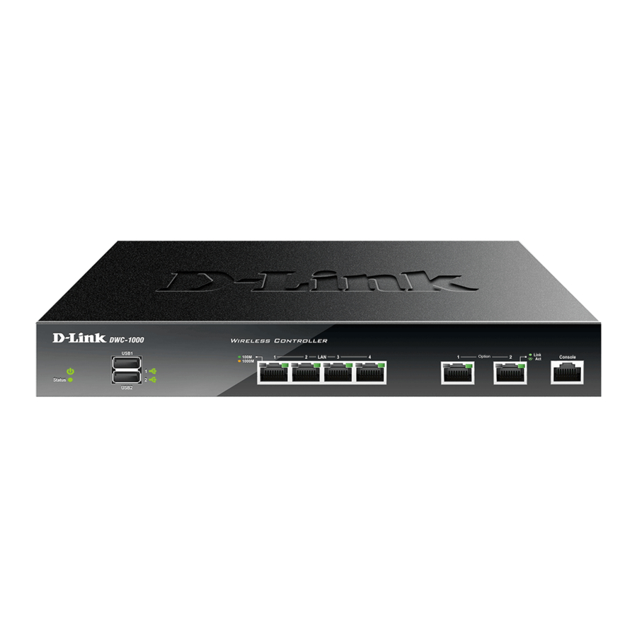
Page 15: Front Panel Ports And Leds
Two Gigabit Option Ports Two Gigabit Ethernet ports labeled Option let you connect the wireless controller to a backbone (requires DWC-1000-VPN-LIC License Pack upgrade – see page 18). Each port has an Activity LED (left) and Link LED (right) – see Table 2-1. -
Page 16: Four Gigabit Ethernet Lan Ports
ON = power-on process complete. OFF= wireless controller is powered OFF. Blink = system is defective and firmware upgrades have failed. Orange ON = power-on process in progress. OFF= wireless controller is in recovery mode following a crash. DWC-1000 Wireless Controller User’s Guide... -
Page 17: Rear Panel
Note: You can also revert the wireless controller to its factory default settings from the FIRMWARE page (see “Restoring Factory Default Settings” on page 203). To use the reset button to perform a factory default reset: 1. Leave power plugged into the wireless controller. DWC-1000 Wireless Controller User’s Guide... -
Page 18: Bottom Panel (Default Ip Address)
Two types of licenses are available for upgrading the wireless controller. • DWC-1000-AP6-LIC License Packs. Allow the wireless controller to manage 6 additional access points. You can upgrade the wireless controller 3 times with these license packs, enabling it to support a maximum of 24 access points. -
Page 19: Connecting The Wireless Controller
PoE switch in the LAN network segment. 3. Connect one of the wireless controller ports labeled LAN (1-4) to the network or directly to a PC. Your installation should resemble the one in Figure 2-5. DWC-1000 Wireless Controller User’s Guide... - Page 20 6. Set the ON/OFF switch on the rear panel of the wireless controller to the ON position. The green Power LED to the left of the front panel USB ports goes ON. If the LED is not ON, see “Power LED is OFF” on page 212. DWC-1000 Wireless Controller User’s Guide...
-
Page 21: Sample Applications
The operating system on the computer that contains the network-interface card (NIC) is configured with the same WEP or WPA network key settings configured on the switch and wireless controller. Figure 2-6. Example of Connecting to a Secured Network DWC-1000 Wireless Controller User’s Guide... -
Page 22: Authenticating To An Authentication Server
There is a shared secret key exchanged between the access point and RADIUS server. • User and user privileges are specified in the RADIUS database. (Servers using other types of authentication, such as Kerberos, have other settings that must be configured.) DWC-1000 Wireless Controller User’s Guide... - Page 23 Optional: Enter the RADIUS accounting server name. Optional: Select a RADIUS use network configuration. Optional: Check RADIUS accounting. Optional: Enter a RADIUS authentication server name. Optional: Enter a RADIUS accounting server name. Click Save Settings. DWC-1000 Wireless Controller User’s Guide...
-
Page 24: Logging In To A Captive Portal
Add the captive portal users to the group and assign a password and idle timeout value to • Select an interface for the captive portal. • Test your settings and make any necessary adjustments. Figure 2-7. Example of a Captive Portal Configuration DWC-1000 Wireless Controller User’s Guide... -
Page 25: Where To Go From Here
ADVANCED > Captive Portal > Captive Portal Setup Test your settings. a. Click a profile. b. Click Show Preview. Where to Go from Here After installing the wireless controller, proceed to Chapter 3 to perform basic configuration procedures. DWC-1000 Wireless Controller User’s Guide... -
Page 26: Basic Configuration
Web Management Interface Layout (page 30) Basic Configuration Procedures (page 31) Using the information in this chapter, you can perform the basic information in minutes and get your wireless controller up and running in a short period of time. DWC-1000 Wireless Controller User’s Guide... -
Page 27: Logging In To The Web Management Interface
2. In the address field of your web browser, type the IP address for the wireless controller web management interface. Its default IP address is http://192.168.10.1. A login prompt appears. If the login prompt does not appear, see “Troubleshooting the Web Management Interface” on page 213. DWC-1000 Wireless Controller User’s Guide... - Page 28 3. If you are logging in for the first time, type the default case-sensitive user name admin and the default case-sensitive password admin in lower-case letters. Note: D-Link recommends that you change the password to a new, more secure password (see “Editing Users” on page 199) and record it in Appendix A.
- Page 29 Basic Configuration 5. To log out of the web management interface, click LOGOUT, which appears to the right of the name of the currently displayed page. DWC-1000 Wireless Controller User’s Guide...
-
Page 30: Web Management Interface Layout
Delete. Removes the selected item from the table or screen configuration. Note: Below the Help menu on the main navigation tab is a Helpful Hints area that provides online help for the page displayed in the workspace. DWC-1000 Wireless Controller User’s Guide... -
Page 31: Basic Configuration Procedures
Basic Configuration Step #4. Confirm Access Point Profile is Associated – see page 39. Basic Configuration Step #6. Use SSID with RADIUS – see page 48. Basic Configuration Step #5. Configure Captive Portal Settings – see page 40. DWC-1000 Wireless Controller User’s Guide... -
Page 32: Basic Configuration Step #1. Enable Dhcp Server (Optional)
Record the settings below; you will refer to them later in this procedure: – IP address: ___________________________________________ – Subnet mask: _________________________________________ 3. Click Save Settings. 4. Wait 60 seconds, and then start your web browser. DWC-1000 Wireless Controller User’s Guide... -
Page 33: Basic Configuration Step #2. Select The Access Points To Be Managed
1. Click STATUS > Access Point Info > APs Summary. The ACCESS POINTS SUMMARY page appears, with a list of the access points that the wireless controller has discovered. DWC-1000 Wireless Controller User’s Guide... - Page 34 Rogue = access point has not tried to contact the wireless controller and the access point’s • MAC address is not in the Valid AP database. Radio Wireless radio mode the access point is using. DWC-1000 Wireless Controller User’s Guide...
-
Page 35: Basic Configuration Step #3. Change The Ssid Name And Set Up Security
1. Click ADVANCED > SSIDs. The following NETWORKS page appears, with a list of the wireless networks configured on the wireless controller. 2. Under the SSID column, click an SSID. The following NETWORKS page appears. DWC-1000 Wireless Controller User’s Guide... - Page 36 Choices are: None = no security mechanism is used. • WEP = enable WEP security. Complete the options in Table 3-4. • WPA/WPA2 = enable WPA/WPA2 security. Complete the options in Table 3-5. • DWC-1000 Wireless Controller User’s Guide...
- Page 37 64 bit = ASCII: 5 characters; Hex: 10 characters • 128 bit = ASCII: 13 characters; Hex: 26 characters • Each client station must be configured to use one of these WEP keys in the same slot as specified here. DWC-1000 Wireless Controller User’s Guide...
- Page 38 Bcast Key Refresh Rate (seconds) Enter a value to set the interval at which the broadcast (group) key is refreshed for clients associated to this VAP. Range: 0 - 86400 seconds (0 = broadcast key is not refreshed) DWC-1000 Wireless Controller User’s Guide...
-
Page 39: Basic Configuration Step #4. Confirm Access Point Profile Is Associated
2. Under Access Point Profile List, check the box to the left of the access point profile you want to update. 3. Click Apply. 4. Wait 30 seconds, and then click Refresh to verify that the profile is associated. Your associated access point is configured and ready to authenticate wireless users. DWC-1000 Wireless Controller User’s Guide... -
Page 40: Basic Configuration Step #5. Configure Captive Portal Settings
Configuring the wireless controller’s captive portal settings is a 4-step process: 1. Create a captive portal group a. Click ADVANCED > Users > Groups. The GROUPS page appears. b. Click Add. The GROUP CONFIGURATION page appears. DWC-1000 Wireless Controller User’s Guide... -
Page 41: Add Captive Portal Users
Enter a name for the group. Description Enter a description of the group. User Type Captive Portal User Check this box. 2. Add captive portal users a. Click ADVANCED > Users > Users. The USERS page appears. DWC-1000 Wireless Controller User’s Guide... - Page 42 Basic Configuration b. Click Add. The USERS CONFIGURATION page appears. DWC-1000 Wireless Controller User’s Guide...
- Page 43 (•). Idle Timeout Enter the number of minutes of inactivity that must occur before the user is logged out of his session automatically. Entering an Idle Timeout value of 0 (zero) means never log out. DWC-1000 Wireless Controller User’s Guide...
-
Page 44: Associate The Captive Portal Group To An Interface
The captive portal is now associated to the selected interface. To test your configuration from a client, connect to the captive portal SSID to log in to the captive portal. Enter an IP address on the captive portal network to see the captive portal. DWC-1000 Wireless Controller User’s Guide... -
Page 45: Customize The Captive Portal Login Page
Under List of Available Profiles, click Add to add a new profile or click the radio button that corresponds to a profile name and click Edit to edit an existing profile. The CUSTOMIZED CAPTIVE PORTAL SETUP page appears. DWC-1000 Wireless Controller User’s Guide... - Page 46 Browser Title Enter the text that will appear in the title of the browser during the captive portal session. Page Background Color Select the background color of the page that appears during the captive portal session. DWC-1000 Wireless Controller User’s Guide...
- Page 47 Under List of Available Profiles, click the profile and then click the Enable button to enable the profile. Under Captive Portal Policies, click a policy and then click the Enable button to enable the policy. DWC-1000 Wireless Controller User’s Guide...
-
Page 48: Basic Configuration Step #6. Use Ssid With Radius
For more information about advanced configuration settings, refer to the DWC-1000 Wireless Controller User Manual and the wireless controller Helpful Hints in the web management interface (see “Web Management Interface Layout”... -
Page 49: Advanced Configuration Settings
For information about additional advanced configuration settings not described in this chapter, see “Additional Advanced Configuration ” on page 77. Note: The procedures in this chapter should only be performed by expert users who understand networking concepts and terminology. DWC-1000 Wireless Controller User’s Guide... -
Page 50: Qos Configuration
To access this feature, click SETUP > QoS > Remark CoS to DSCP. To configure QoS mode: 1. Click SETUP > QoS > LAN QoS > Trust Mode Configuration. The LAN QOS page appears. DWC-1000 Wireless Controller User’s Guide... - Page 51 3. Under LAN QoS configuration, use the Classify Using drop-down list to select whether DSCP or CoS will be used for the port. 4. Click Save Settings. 5. Proceed to “Defining DSCP and CoS Settings” on page 52 to configure values for DSCP and CoS and their priority. DWC-1000 Wireless Controller User’s Guide...
-
Page 52: Defining Dscp And Cos Settings
DSCP fields in IP packets. 1. Click SETUP > QoS > LAN QoS > IP DSCP Configuration. The PORT DSCP MAPPING page appears. Each row corresponds to a DSCP field in an IP packet. DWC-1000 Wireless Controller User’s Guide... -
Page 53: Configuring Cos Priorities
CoS fields in the IP packets. 1. Click SETUP > QoS > LAN QoS > 801.P Priority. The PORT COS MAPPING page appears. Each row corresponds to a CoS field in an IP packet. DWC-1000 Wireless Controller User’s Guide... - Page 54 2. On the appropriate row, use the Queue drop-down list to select one of the following priorities: – Highest – Medium – – Lowest 3. Repeat step 2 for each additional CoS field you want to prioritize. 4. When you finish, click Save Settings. DWC-1000 Wireless Controller User’s Guide...
- Page 55 5. On the appropriate row, use the Queue drop-down list to select one of the following priorities: – Highest – Medium – – Lowest 6. Repeat step 2 for each additional CoS field you want to prioritize. 7. When you finish, click Save Settings. DWC-1000 Wireless Controller User’s Guide...
-
Page 56: Vlans
Path: SETUP > VLAN Settings > VLAN Configuration By default, the wireless controller’s VLAN function is disabled. To enable it: 1. Click SETUP > VLAN Settings > VLAN Configuration. The VLAN CONFIGURATION page appears. 2. Under VLAN Configuration, check Enable VLAN. DWC-1000 Wireless Controller User’s Guide... -
Page 57: Creating Vlans
VLANs. After you create VLANs, you can use the same page to view, edit, and delete VLANs. To create a VLAN: 1. Click SETUP > VLAN Settings > Available VLANs. The AVAILABLE VLANs page appears. 2. Click Add. The following page appears. DWC-1000 Wireless Controller User’s Guide... - Page 58 Enter a unique ID to this VLAN. Range: 2 - 4093 Inter VLAN Routing Enable Allows or denies communication between VLAN networks. Choices are: Checked = allow communications between different VLANs. • Unchecked = deny communications between different VLANs. • DWC-1000 Wireless Controller User’s Guide...
-
Page 59: Editing Vlans
To edit a VLAN: 1. Click SETUP > VLAN Settings > Available VLANs. The AVAILABLE VLANs page appears. 2. Under List of available VLANs, click the VLAN you want to edit and click Edit. The following page appears. DWC-1000 Wireless Controller User’s Guide... - Page 60 Advanced Configuration Settings 3. Change the Inter VLAN Routing Enable setting as desired (see Table 4-1 on page 58). 4. Click Save Settings. DWC-1000 Wireless Controller User’s Guide...
-
Page 61: Deleting Vlans
1. Click SETUP > VLAN Settings > Available VLANs. The AVAILABLE VLANs page appears. 2. Under List of available VLANs, click the VLAN you want to delete. (Or click the box next to Name to select all VLANs.) 3. Click Delete. The selected VLAN is deleted. DWC-1000 Wireless Controller User’s Guide... -
Page 62: Port Vlans
After you enable the wireless controller’s VLAN function, use the PORT VLANS page to configure the ports participating in the VLAN. 1. Click SETUP > VLAN Settings > Port VLAN. The PORT VLAN page appears. DWC-1000 Wireless Controller User’s Guide... -
Page 63: Multivlan Subnets
1. Click SETUP > VLAN Settings > Multiple VLAN Subnets. The MULTI VLAN SUBNETS page appears. 2. To edit a multi-subnet VLAN, check it and click Edit. The MULTI VLAN SUBNET CONFIG page appears with the settings for the selected VLAN. DWC-1000 Wireless Controller User’s Guide... - Page 64 DHCP Server = select this setting to use the wireless controller as a DHCP server. Complete • the remaining settings on the page. DHCP Relay = if you select this setting, you need only enter the relay gateway information. • Domain Name Enter the domain name for the VLAN. DWC-1000 Wireless Controller User’s Guide...
- Page 65 DNS IP addresses, along with the IP address where the DNS proxy is running (i.e., the wireless controller's LAN IP). Unchecked = all DHCP clients receive the DNS IP addresses of the ISP, excluding the DNS • proxy IP address. DWC-1000 Wireless Controller User’s Guide...
-
Page 66: Dmz Settings
Path: SETUP > Internet Settings > Configurable Port To configure a port to operate as a DMZ: 1. Click SETUP > Internet Settings > Configurable Port. The CONFIGURABLE PORT page appears. 2. Under Configurable Port Status, click DMZ. 3. Click Save Settings. DWC-1000 Wireless Controller User’s Guide... -
Page 67: Configuring Dmz Settings
1000-VPN-LIC License Pack (see “Licenses” on page 18). 1. Click SETUP > DMZ Setup > DMZ Setup Configuration. The DMZ SETUP page appears. 2. Complete the fields in the page (see Table 4-3). 3. Click Save Settings. DWC-1000 Wireless Controller User’s Guide... - Page 68 DNS proxy is enabled, then clients can make requests to the wireless controller and the controller, in turn, sends those requests to the DNS servers of the active connection. Unchecked = disable DNS proxy on this LAN. • DWC-1000 Wireless Controller User’s Guide...
-
Page 69: Static Routing
Adding a Static Route Path: ADVANCED > Routing > Static Routing To add a static route: 1. Click ADVANCED > Routing > Static Routing. The STATIC ROUTING page appears. 2. Click Add. The STATIC ROUTE CONFIGURATION page appears. DWC-1000 Wireless Controller User’s Guide... - Page 70 LAN > VLAN = the wireless controller’s LAN or VLAN port will interface to the static route. • Gateway IP Address Enter the IP address of the gateway router, which is the next hop address for the wireless controller. Metric Enter the administrative distance of the route. DWC-1000 Wireless Controller User’s Guide...
-
Page 71: Editing Static Routes
1. Click ADVANCED > Routing > Static Routing. The STATIC ROUTING page appears. 2. Under List of available static routes, click the static route you want to edit and click Edit. 3. Change the desired settings (see Table 4-4 on page 70). 4. Click Save Settings. DWC-1000 Wireless Controller User’s Guide... -
Page 72: Deleting Static Routes
2. Under List of available Static Routes, click the static route you want to delete. (Or click the box next to Name to select all static routes.) 3. Click Delete. The selected static route is deleted. DWC-1000 Wireless Controller User’s Guide... -
Page 73: Auto-Failover Settings
The Option port then takes over all functions of the primary port. The wireless controller supports auto-failover when: • A D-Link VPN license key has been installed (see “Activating Licenses” on page 208). • Multiple Option ports are configured. - Page 74 Retry Interval is Enter a number that tells the wireless controller how often, in seconds, to run the failure detection method(s) configured above. Failover after Enter the number of retries the wireless controller attempts before initiating failover. DWC-1000 Wireless Controller User’s Guide...
-
Page 75: Load Balancing Settings
Load Balancing Settings Path: SETUP > Internal Settings > Option Mode The wireless controller supports load balancing when: • A D-Link VPN license key has been installed (see “Activating Licenses” on page 208). • Multiple Option ports are configured. •... - Page 76 Option port. Max Bandwidth Enter the maximum bandwidth tolerable by the Primary Option. If the bandwidth falls below the load tolerance value of configured Max Bandwidth, the wireless controller switches to the secondary Option port. DWC-1000 Wireless Controller User’s Guide...
-
Page 77: Additional Advanced Configuration Settings
ADVANCED > IPv6 > IPv6 LAN > IPv6 LAN Config IP v6 options* ADVANCED > IPv6 > IPv6 LAN > IPv6 Option 1 Config ADVANCED > IPv6 > IPv6 LAN > IPv6 Option 2 Config DWC-1000 Wireless Controller User’s Guide... - Page 78 System check TOOLS > System Check Universal Plug and Play ADVANCED > Advanced Network > UPnP Voice VLANs SETUP > VLAN Settings > MAC-based VLAN > Voice VLAN WLAN global settings SETUP > WLAN Global Settings DWC-1000 Wireless Controller User’s Guide...
-
Page 79: Securing Your Network
For information about additional security settings not described in this chapter, see “Additional Security Settings” on page 91. Note: The procedures in this chapter should only be performed by expert users who understand networking concepts and terminology. DWC-1000 Wireless Controller User’s Guide... -
Page 80: Managing Clients
Viewing Known Clients and Adding Clients Path: ADVANCED > Client To view known clients: 1. Click ADVANCED > Client. The KNOWN CLIENTS page appears, with a list of the wireless clients in the Known Client database. DWC-1000 Wireless Controller User’s Guide... - Page 81 Securing Your Network 2. Click Add. The STATIC ROUTE CONFIGURATION page appears. DWC-1000 Wireless Controller User’s Guide...
- Page 82 Configuration page to determine how to handle the client. Grant = allow the client with the specified MAC address to access the network. • Deny = prohibit the client with the specified MAC address from accessing the network. • DWC-1000 Wireless Controller User’s Guide...
-
Page 83: Editing Clients
1. Click ADVANCED > Client. The KNOWN CLIENTS page appears. 2. Under List of Known Clients, click the client you want to edit and click Edit. 3. Change the desired settings (see Table 5-1 on page 82). 4. Click Save Settings. DWC-1000 Wireless Controller User’s Guide... -
Page 84: Deleting Clients
2. Under List of Known Clients, click the client you want to delete. (Or click the box next to List of Known Clients to select all clients.) 3. Click Delete. The selected client is deleted. DWC-1000 Wireless Controller User’s Guide... -
Page 85: Content Filtering
To enable content filtering: 1. Click ADVANCED > Website Filter > Content Filtering. The CONTENT FILTERING page appears. 2. Under Content Filtering Configuration, check Enable Content Filtering. The fields under Web Components become available. DWC-1000 Wireless Controller User’s Guide... -
Page 86: Specifying Approved Urls
Note: The approved URLs you define here can be exported to a CSV file (see “Exporting Web Filters” on page 89). To specify approved URLs: 1. Click ADVANCED > Website Filter > Approved URLs. The APPROVED URLS page appears. DWC-1000 Wireless Controller User’s Guide... - Page 87 When the APPROVED URL CONFIGURATION page appears, edit the URL in the URL field and click Save Settings. 5. To delete an approved URL, check the URL under Approved URLs List and click Delete. The URL is deleted without displaying a precautionary message. DWC-1000 Wireless Controller User’s Guide...
-
Page 88: Specifying Blocked Keywords
To block all URLs or certain URLs based on keywords: 1. Click ADVANCED > Website Filter > Blocked Keywords. The BLOCKED KEYWORDS page appears. 2. To block all URLs, under Blocked All URL Configuration, check Block All URLs. DWC-1000 Wireless Controller User’s Guide... -
Page 89: Exporting Web Filters
CSV file from which they can be downloaded to a local host. To enable Web filters: 1. Click ADVANCED > Website Filter > Export. The EXPORT WEB FILTER page appears. DWC-1000 Wireless Controller User’s Guide... - Page 90 3. To export the blocked keywords you defined under “Specifying Blocked Keywords” on page 88, under Export Web Filter, click the Export button next to Export Blocked Keywords. When the File Download dialog box appears, click Save and save the file to a location. DWC-1000 Wireless Controller User’s Guide...
-
Page 91: Additional Security Settings
The following table describes these settings. For more information, go to the page in the web management interface and then access the wireless controller online help in the Helpful Hints area (see Figure 3-1 on page 31). Note: Asterisks in the table below indicate settings that require a DWC-1000-VPN-LIC License Pack. Security Setting... -
Page 92: Vpn Settings
For information about additional VPN settings not described in this chapter, see “Additional VPN Settings” on page 123. Note: The procedures in this chapter should only be performed by expert users who understand networking concepts and terminology. DWC-1000 Wireless Controller User’s Guide... -
Page 93: Configuring Vpn Clients
IPsec VPN tunnel. For more information, refer to the documentation for the VPN client software. Figure 6-1. Example of Gateway-to-Gateway IPsec VPN Tunnel Using Two Wireless Controllers Connected to the Internet DWC-1000 Wireless Controller User’s Guide... - Page 94 Figure 6-2 shows an example of a configuration where three IPsec clients are connected to an internal network through the wireless controller IPsec gateway. Figure 6-2. Example of Three IPsec Client Connections to an Internal Network through the Wireless Controller IPsec Gateway DWC-1000 Wireless Controller User’s Guide...
-
Page 95: Configuring Ipsec Policies
Path: SETUP > VPN Settings > IPsec > IPsec Policies To add an IPsec policy: 1. Click SETUP > VPN Settings > IPsec > IPsec Policies. The IPSEC POLICIES page appears. 2. Click Add. The IPSEC CONFIGURATION page appears. DWC-1000 Wireless Controller User’s Guide... - Page 96 Manual Policy = all settings, including the keys, for the VPN tunnel are manually entered for • each end point. No third-party server or organization is involved. IP Protocol Version Select the Internet protocol version to be used. Choices are: IPv4 • IPv6 • DWC-1000 Wireless Controller User’s Guide...
- Page 97 • Unchecked = VPN clients do not get an IP address. • Tunnel mode IPsec policies require local and remote traffic settings to be defined. For both local and remote endpoints configure the following settings. DWC-1000 Wireless Controller User’s Guide...
- Page 98 Enables or disables Network Address Translation (NAT) traversal. Choices are: On = select this setting if you expect any NAT to occur during IPsec communication. • Off = select this setting if you do not expect NAT to occur during IPsec communication. • DWC-1000 Wireless Controller User’s Guide...
- Page 99 SHA-1 = Secure Hash Algorithm (SHA-1) hash function. SHA-1 uses a 160-bit encryption key • and is stronger than MD5. SHA2-256 = SHA-256 hash function that uses 32-bit words. • SHA2-384 = SHA-384 hash function. • SHA2-512 = SHA-512 hash function that uses 64-bit words. • DWC-1000 Wireless Controller User’s Guide...
- Page 100 This section is used when Policy Type = Manual under the General section of this page. The Manual Policy creates a Security Association (SA) based on the following static inputs. For an example, see “Example of a Manual Policy” on page 103. DWC-1000 Wireless Controller User’s Guide...
- Page 101 SHA2=512 = 64 characters • Key-Out Enter the integrity key (for ESP with Integrity-mode) for the outbound policy. The length of the key depends on the algorithm chosen, as shown for Key-In. Phase 2 (Auto Policy Parameters) DWC-1000 Wireless Controller User’s Guide...
- Page 102 Enables or disables Perfect Forward Secrecy (PFS) to improve security. While slower, this protocol helps to prevent eavesdroppers by ensuring that a Diffie-Hellman exchange is performed for every phase-2 negotiation. Choices are: Checked = enable PFS. • Unchecked = disable PFS. • DWC-1000 Wireless Controller User’s Guide...
-
Page 103: Example Of A Manual Policy
Policy Type: Manual Policy Local Gateway: Option Remote Endpoint: 10.0.0.1 Local IP: Subnet 192.168.20.0 255.255.255.0 Remote IP: Subnet 192.168.20.0 255.255.255.0 SPI-Incoming: 0x2222 Encryption Algorithm: DES Key-In: 33334444 Key-Out: 11112222 SPI-Outgoing: 0x1111 Integrity Algorithm: MD5 Key-In: 5566778888776655 Key-Out: 1122334444332211 DWC-1000 Wireless Controller User’s Guide... -
Page 104: Editing Ipsec Policies
2. Under List of VPN Policies, check the IPsec auto policy or manual policy you want to edit and click Edit. The IPSEC CONFIGURATION page appears. 3. Complete the fields in the page (see Table 6-1). 4. Click Save Settings. DWC-1000 Wireless Controller User’s Guide... -
Page 105: Enabling Ipsec Policies
1. Click SETUP > VPN Settings > IPsec > IPsec Policies. The IPSEC POLICIES page appears. 2. Under List of VPN Policies, check the IPsec auto policy or manual policy you want to enable and click Enable. DWC-1000 Wireless Controller User’s Guide... -
Page 106: Disabling Ipsec Policies
1. Click SETUP > VPN Settings > IPsec > IPsec Policies. The IPSEC POLICIES page appears. 2. Under List of VPN Policies, check the IPsec auto policy or manual policy you want to disable and click Disable. DWC-1000 Wireless Controller User’s Guide... -
Page 107: Exporting Ipsec Policies
Export. The VPN CONFIG EXPORT WIZARD FOR REMOTE DSR appears. 3. Review and complete the settings as needed. 4. Click Export Policy at the bottom of the page to export the settings. DWC-1000 Wireless Controller User’s Guide... -
Page 108: Deleting Ipsec Policies
1. Click SETUP > VPN Settings > IPsec > IPsec Policies. The IPSEC POLICIES page appears. 2. Under List of VPN Policies, check the IPsec auto policy or manual policy you want to delete and click Delete. DWC-1000 Wireless Controller User’s Guide... -
Page 109: Mode Config Settings
Split DNS directs internal hosts to an internal domain name server for name resolution and external hosts are directed to an external domain DWC-1000 Wireless Controller User’s Guide... - Page 110 When you click Add, the SPLIT DNS NAMES page appears. Enter a Domain Name in the Domain Name field and click Save Settings. The Split DNS Name section provides Edit and Delete buttons for changing or deleting split DNS name configurations. DWC-1000 Wireless Controller User’s Guide...
- Page 111 In a split DNS infrastructure, you create two zones for the same domain, one to be used by the internal network and the other used by the external network. Split DNS directs internal hosts to an internal domain name server for name resolution and external hosts are directed to an external domain name server for name resolution. DWC-1000 Wireless Controller User’s Guide...
-
Page 112: Dhcp Range
Enter the starting IP address to be allocated in this range. Ending IP Address Enter the last IP address to be allocated in this range. Subnet Mask Enter the subnet mask for the IP address range. DWC-1000 Wireless Controller User’s Guide... -
Page 113: Pptp/Lt2P Tunnels
STATUS > Active VPNs page to establish a PPTP VPN tunnel. To configure PPTP clients: 1. Click SETUP > VPN Settings > PPTP > PPTP Client. The PPTP CLIENT page appears. 2. Complete the fields in the page (see Table 6-4). DWC-1000 Wireless Controller User’s Guide... -
Page 114: Configuring Pptp Servers
Checked = enable MPPE encryption. • Unchecked = disable MPPE encryption. • Idle Time Out If there is no traffic from a user for more than the specified time-out, the connection is disconnected. Configuring PPTP Servers DWC-1000 Wireless Controller User’s Guide... - Page 115 To configure PPTP clients: 1. Click SETUP > VPN Settings > PPTP > PPTP Server. The PPTP SERVER page appears. 2. Complete the fields in the page (see Table 6-5). 3. Click Save Settings. DWC-1000 Wireless Controller User’s Guide...
- Page 116 RSA Message Digest 4 challenge-and-reply protocol. This only works on Microsoft systems and enables data encryption. To select this authentication method causes all data to be encrypted. Choices are: Checked = enable support for MS-CHAP. • Unchecked = disable support for MS-CHAP. • DWC-1000 Wireless Controller User’s Guide...
- Page 117 User Time-out Idle TimeOut If there is no traffic from a user for more than the specified time out, the connection is disconnected. Entering an Idle TimeOut value of 0 (zero) means never log out. DWC-1000 Wireless Controller User’s Guide...
-
Page 118: L2Tp Tunnel Support
To configure L2TP tunnel support: 1. Click SETUP > VPN Settings > L2TP > L2TP Server. The L2TP SERVER page appears. 2. Complete the fields in the page (see Table 6-6). 3. Click Save Settings. DWC-1000 Wireless Controller User’s Guide... - Page 119 RSA Message Digest 4 challenge-and-reply protocol. This only works on Microsoft systems and enables data encryption. To select this authentication method causes all data to be encrypted. Choices are: Checked = enable support for MS-CHAP. • Unchecked = disable support for MS-CHAP. • DWC-1000 Wireless Controller User’s Guide...
- Page 120 User Time-out Idle TimeOut If there is no traffic from a user for more than the specified time out, the connection is disconnected. Entering an Idle TimeOut value of 0 (zero) means never log out. DWC-1000 Wireless Controller User’s Guide...
-
Page 121: Openvpn Support
To configure OpenVPN support: 1. Click SETUP > VPN Settings > OpenVPN > Open VPN Configuration. The OPENVPN CONFIGURATION page appears. 2. Complete the fields in the page (see Table 6-7). 3. Click Save Settings. DWC-1000 Wireless Controller User’s Guide... - Page 122 Shows whether the user must download the auto-login profile and upload here to connect this wireless controller to the OpenVPN access server. File Use this field and the Browse button to select the file containing the profile. DWC-1000 Wireless Controller User’s Guide...
-
Page 123: Additional Vpn Settings
For more information, go to the page in the web management interface and then access the wireless controller online help in the Helpful Hints area (see Figure 3-1 on page 31). Note: Asterisks in the table below indicate settings that require a DWC-1000-VPN-LIC License Pack. VPN Setting... -
Page 124: Viewing Status And Statistics
Shows a variety of information about each access point that the wireless controller is managing. Status > Access Point Info > Authentication Shows information about access points that failed to establish communication Failure Status with the wireless controller. DWC-1000 Wireless Controller User’s Guide... - Page 125 STATUS > Wireless Client Info > Pre-Auth Shows detected clients that have made pre-authentication requests and identifies History the access points that received the requests. STATUS > Wireless Client Info > Roam History Shows a client’s roaming history between access points. DWC-1000 Wireless Controller User’s Guide...
-
Page 126: Viewing Cpu And Memory Utilization
DASHBOARD page is organized into the following sections (see Table 7-1): • CPU Utilization – shows statistics for the wireless controller’s processor. • Memory Utilization – shows the system’s memory status. Figure 7-1. DASHBOARD Page DWC-1000 Wireless Controller User’s Guide... - Page 127 Total available volatile physical memory. Used Memory Memory used by all processes in the system. Free Memory Available free memory in the system. Cached Memory Cached memory in the system. Buffer Memory Buffered memory in the system. DWC-1000 Wireless Controller User’s Guide...
-
Page 128: Viewing System Status
Setup and Advanced menus. This page is organized into the following sections: • General - shows system name, firmware and WLAN module version, and serial number. • Option Information and LAN Information – shows information based on the administrator configuration parameters. DWC-1000 Wireless Controller User’s Guide... - Page 129 Viewing Status and Statistics Figure 7-2. SYSTEM STATUS Page DWC-1000 Wireless Controller User’s Guide...
-
Page 130: Viewing Managed Access Point Information
The WIRELESS LAN AP INFORMATION page shows details about the managed access points (see Table 7-2). Checking a managed access point enables the buttons described in Table 7-3. Figure 7-3. WIRELESS LAN AP INFORMATION Page DWC-1000 Wireless Controller User’s Guide... - Page 131 Shows summary information about the virtual access points (VAPs) for the selected access point and the access point radio interface that the wireless controller manages. View Distributed Tunnelling Details Shows information about the L2 tunnels currently in use on the access point. DWC-1000 Wireless Controller User’s Guide...
-
Page 132: Viewing Cluster Information
One wireless controller in a cluster is elected as a Cluster Controller. The Cluster Controller collects status and statistics from the other controllers in the cluster, including information about the access point’s peer controller and the clients associated to those access points. Figure 7-4. CLUSTER INFORMATION Page DWC-1000 Wireless Controller User’s Guide... - Page 133 Discovery method of the given peer wireless controller, either through an L2 Poll or IP Poll. Managed AP Count Number of access points that the wireless controller manages currently. Time since last communication with the wireless controller, in hours, minutes, and seconds. DWC-1000 Wireless Controller User’s Guide...
-
Page 134: Viewing Hardware And Usage Statistics
Interface statistics for wired connections (LAN, Option1, Option 2/DMZ, and VLANs) show information about packets through and packets dropped by the interface. Click refresh to have this page retrieve the most current statistics (see Table 7-1): DWC-1000 Wireless Controller User’s Guide... - Page 135 Viewing Status and Statistics Figure 7-5. DASHBOARD Page DWC-1000 Wireless Controller User’s Guide...
-
Page 136: Wired Port Statistics
The statistics table has an auto-refresh control for displaying the most current port level data at each page refresh. The default auto-refresh for this page is 10 seconds. Figure 7-6. DEVICE STATISTICS Page DWC-1000 Wireless Controller User’s Guide... -
Page 137: Managed Access Points And Associated Clients Statistics
Number of packets transmitted to the client station. Packets Received Number of packets received by the client station. Bytes Transmitted Number of bytes transmitted to the client station. Bytes Received Number of bytes received by the client station. DWC-1000 Wireless Controller User’s Guide... - Page 138 Shows information about access points that the client detects. The access point-access point tunnelling mode is used to support L3 roaming for wireless clients without forwarding any data traffic to the wireless controller. Refresh Updates the information shown on the page. DWC-1000 Wireless Controller User’s Guide...
-
Page 139: Lan-Associated Clients
This page shows information about the traffic a wireless client receives and transmits while it is associated with a single access point. Use the menu above the table to view details about an associated client. Each client is identified by its MAC address. Figure 7-8. ASSOCIATED CLIENTS STATISTICS Page DWC-1000 Wireless Controller User’s Guide... - Page 140 Total number of duplicate packets received from the client station. Table 7-8. Buttons on the ASSOCIATED CLIENTS STATISTICS Page Field Description Refresh Updates the information shown on the page. View Details Shows detailed status associated client. DWC-1000 Wireless Controller User’s Guide...
-
Page 141: Wlan-Associated Clients
Table 7-9. Fields on the ASSOCIATED CLIENTS STATISTICS Page Field Description MAC Address MAC address of the client station. Packets Transmitted Number of packets transmitted to the client station. Packet Received Number of packets received by the client station. DWC-1000 Wireless Controller User’s Guide... -
Page 142: Sessions Through The Wireless Controller
The ACTIVE SESSIONS page shows the following information about the active Internet sessions through the wireless controller: • Local and remote IP addresses • Protocol used during the Internet sessions • State Figure 7-10. ACTIVE SESSIONS Page DWC-1000 Wireless Controller User’s Guide... -
Page 143: Associated Clients
Name of the network on which the client is connected. BSSID Ethernet MAC address for the managed access point/virtual access point where this client is associated. Detected IP Address IPv4 address of the client, if available. DWC-1000 Wireless Controller User’s Guide... - Page 144 Each access point has a set of Virtual Access Points (VAPs) per radio, and every VAP has a unique MAC address (BSSID). This displays the VAP Associated Client Status page, which shows information about the VAPs on the managed AP that have associated wireless clients. DWC-1000 Wireless Controller User’s Guide...
-
Page 145: Lan Clients
LAN controller. The LAN CLIENTS page shows the: • NetBios name (if available) • IP address of discovered LAN hosts • MAC address of discovered LAN hosts Figure 7-12. LAN CLIENTS Page DWC-1000 Wireless Controller User’s Guide... -
Page 146: Detected Clients
Client Status page shows information about clients that have authenticated with an access point as well information about clients that disassociate and are no longer connected to the system. Figure 7-13. DETECTED CLIENT STATUS Page DWC-1000 Wireless Controller User’s Guide... - Page 147 Rogue = client is classified as a threat by one of the threat-detection algorithms. • Time since any event has been received for this client that updated the detected client database entry. Create Time Time since this entry was first added to the detected client database. DWC-1000 Wireless Controller User’s Guide...
-
Page 148: Access Point Status
The ACCESS POINT page shows summary information about managed, failed, and rogue access points the wireless controller has discovered or detected. A pie chart at the bottom of the page provides a graphical representation of the total access point utilization. Figure 7-14. ACCESS POINT Page DWC-1000 Wireless Controller User’s Guide... - Page 149 Maximum number of access points that can be managed by the cluster. in Peer Group WLAN Utilization Total network utilization across all access points managed by this controller. This value is based on global statistics. DWC-1000 Wireless Controller User’s Guide...
-
Page 150: Access Point Summary
Path: STATUS > Access Points Info > APs Summary The ACCESS POINTS SUMMARY page shows summary information about managed, failed, and rogue access points the wireless controller has discovered or detected. Status entries can be deleted manually. Figure 7-15. ACCESS POINT Page DWC-1000 Wireless Controller User’s Guide... - Page 151 To view details for a configured access point, check its box next to the MAC address and then click View Details. The AP RF SCAN STATUS page appears, with detailed information about the access point (see “AP RF Scan Status” on page 156). Refresh Updates the information shown on the page. DWC-1000 Wireless Controller User’s Guide...
-
Page 152: Managed Access Point
Path: STATUS > Access Point Info > Managed AP Status The MANAGED AP STATUS page shows a variety of information about each access point that the wireless controller is managing. Figure 7-16. MANAGED AP STATUS Page DWC-1000 Wireless Controller User’s Guide... - Page 153 Shows information about wireless clients associated with an AP or detected by the access point radio. View VAP Details Shows summary information about the virtual access points (VAPs) for the selected access point and radio interface on the access points that the controller manages. DWC-1000 Wireless Controller User’s Guide...
-
Page 154: Authentication Failure Status
AUTHENTICATION FAILURE STATUS page shows information about access points that failed to establish communication with the wireless controller. Figure 7-17. AP AUTHENTICATION FAILURE STATUS Page An access point can fail due to any of the reasons in Table 7-18. DWC-1000 Wireless Controller User’s Guide... - Page 155 Local Authentication • No Database Entry • Not Managed • RADIUS Authentication • RADIUS Challenged • RADIUS Unreachable • Invalid RADIUS Response • Invalid Profile ID • Profile Mismatch-Hardware Type • Time since failure occurred. DWC-1000 Wireless Controller User’s Guide...
-
Page 156: Ap Rf Scan Status
The AP RF SCAN STATUS page shows information about other access points and wireless clients that the wireless controller has detected. Figure 7-18. AP RF SCAN STATUS Page DWC-1000 Wireless Controller User’s Guide... - Page 157 Time since this access point was last detected in an RF scan. Status entries for this page are collected at a point in time and eventually age out. The age value for each entry shows how long ago the wireless controller recorded the entry. DWC-1000 Wireless Controller User’s Guide...
-
Page 158: Global Status
The wireless controller collects information periodically from the access points it manages and from the associated peer controller. The SUMMARY page shows status and statistics about the wireless controller and the objects associated with it. Figure 7-19. SUMMARY Page DWC-1000 Wireless Controller User’s Guide... - Page 159 Total number of clients in the database. This total includes clients with an Associated, Authenticated, or Disassociated status. Authenticated Clients Total number of clients in the associated client database with an Authenticated status. 802.11a Clients Total number of IEEE 802.11a only clients that are authenticated. DWC-1000 Wireless Controller User’s Guide...
- Page 160 Total number of clients for which the system was unable to set up a distributed tunnel when client roamed. Table 7-22. Buttons on the SUMMARY Page Button Description Refresh Updates the information shown on the page. Clear Statistics Reset all counters on the page to zero. DWC-1000 Wireless Controller User’s Guide...
-
Page 161: Peer Controller Status
One wireless controller in a cluster is elected as a Cluster Controller. The Cluster Controller collects status and statistics from the other wireless controllers in the cluster, including information about the access point peer controllers and the clients associated to those access points. DWC-1000 Wireless Controller User’s Guide... - Page 162 Discovery method of the given peer controller, which can be through an L2 Poll or IP Poll. Managed AP Count Number of access points that the wireless controller manages currently. Time since last communication with the controller in hours, minutes, and seconds. DWC-1000 Wireless Controller User’s Guide...
-
Page 163: Peer Controller Configuration Status
Day and time when the configuration was applied to the wireless controller. The time is displayed as Coordinated Universal Time (UTC). This information is only useful if the administrator has configured each peer controller to use the network time protocol (NTP). DWC-1000 Wireless Controller User’s Guide... -
Page 164: Peer Controller Managed Ap Status
Use the drop-down list at the top of this page to select the peer controller associated with the access point whose information you want to display. Each peer controller is identified by its IP address. DWC-1000 Wireless Controller User’s Guide... - Page 165 Descriptive location configured for the managed access point. AP IP Address IP address of the access point. Profile Access point profile that the wireless controller applies to the access point. Hardware ID Hardware ID associated with the access point hardware platform. DWC-1000 Wireless Controller User’s Guide...
-
Page 166: Ip Discovery
Path: STATUS > Global Info > IP Discovery The IP DISCOVERY page shows IP addresses of peer controllers and access points for the wireless controller to discover and associate with as part of the WLAN. DWC-1000 Wireless Controller User’s Guide... - Page 167 • address in the L3/IP discovery list and was unable to authenticate or validate the device. If the device is an access point, an entry and a failure reason appear in the AP failure list. DWC-1000 Wireless Controller User’s Guide...
-
Page 168: Configuration Receive Status
In addition to keeping the controllers synchronized, this function lets you manage all wireless controllers in the cluster from one controller. The CONFIGURATION RECEIVE STATUS page provides information about the configuration a controller has received from one of its peers. DWC-1000 Wireless Controller User’s Guide... - Page 169 Use the drop-down list at the top of this page to select a peer controller whose access point information you want to view. Each peer controller is identified by its IP address. DWC-1000 Wireless Controller User’s Guide...
-
Page 170: Ap Hardware Capability
Hardware Type Description Describes the platform and the supported IEEE 802.11 modes. Radio Count Shows whether the hardware supports one radio or two radios. Image Type Shows the type of software the hardware requires. DWC-1000 Wireless Controller User’s Guide... -
Page 171: Client Status
Viewing Status and Statistics Client Status Path: STATUS > Dashboard > Client The CLIENT STATISTICS page shows information about all the clients connected through managed access points. DWC-1000 Wireless Controller User’s Guide... - Page 172 Current number of Pre-authentication history entries the system is using. Entries Maximum Roam History Entries Maximum number of entries that can be recorded in the roam history for all detected clients. Total Roam History Entries Number of Pre-authentication history entries the system is using. DWC-1000 Wireless Controller User’s Guide...
-
Page 173: Associated Client Status
SSID Network on which the client is connected. BSSID Ethernet MAC address for the managed access point Virtual Access Point where this client is associated. Detected IP Address IPv4 address of the client, if available. DWC-1000 Wireless Controller User’s Guide... - Page 174 WLAN access. View VAP Details Shows information about the VAPs on the managed access point that have associated wireless clients. View Neighbor AP Details Shows information about access points that the client detects. DWC-1000 Wireless Controller User’s Guide...
-
Page 175: Associated Client Ssid Status
The SSID ASSOCIATED CLIENT STATUS page shows SSID information for the wireless clients on the WLAN. Table 7-32. Fields on the SSID ASSOCIATED CLIENT STATUS Page Field Description SSID Network on which the client is connected. Client MAC Address Ethernet address of the client station. DWC-1000 Wireless Controller User’s Guide... - Page 176 Table 7-33. Buttons on the SSID ASSOCIATED CLIENT STATUS Page Field Description Disassociate Disassociates the selected client from the managed access point. View Client Details Shows associated client details. Refresh Updates the information on the page. DWC-1000 Wireless Controller User’s Guide...
-
Page 177: Associated Client Vap Status
(BSSID). The VAP ASSOCIATED CLIENT STATUS page shows information about the VAPs on the managed access point that have associated wireless clients. To disconnect a client from an access point, check the box next to the BSSID and click Disassociate. DWC-1000 Wireless Controller User’s Guide... - Page 178 IP address of the client station. Table 7-35. Buttons on the VAP ASSOCIATED CLIENT STATUS Page Field Description Disassociate Disassociates the selected client from the managed access point. Refresh Updates the information on the page. DWC-1000 Wireless Controller User’s Guide...
-
Page 179: Controller Associated Client Status
Table 7-36. Fields on the CONTROLLER ASSOCIATED CLIENT STATUS Page Field Description Controller IP Address IP address of the controller that manages the access point to which the client is associated. Client MAC Address MAC address of the associated client. DWC-1000 Wireless Controller User’s Guide... - Page 180 Table 7-37. Buttons on the CONTROLLER ASSOCIATED CLIENT STATUS Page Field Description Disassociate Disassociates the selected client from the managed access point. View Client Details Displays associated client details. Refresh Updates the information on the page. DWC-1000 Wireless Controller User’s Guide...
-
Page 181: Detected Client Status
The DETECTED CLIENT STATUS page shows information about clients that have authenticated with an access point, as well information about clients that disassociate and are no longer connected to the system. DWC-1000 Wireless Controller User’s Guide... - Page 182 If the detected client fails any of the tests that classify it as a threat, it appears as a Rogue again. Refresh Updates the information on the page. DWC-1000 Wireless Controller User’s Guide...
-
Page 183: Pre-Authorization History
User name of client that authenticated via 802.1X. Pre-Authorization Status Indicates whether the client successfully authenticated. Shows a status of Success or Failure. Table 7-41. Button on the DETECTED CLIENT STATUS Page Field Description Refresh Updates the information on the page. DWC-1000 Wireless Controller User’s Guide... -
Page 184: Detected Client Roam History
Table 7-43. Buttons on the ROAM HISTORY Page Field Description Refresh Updates the information on the page. Purge History Purges the history when the list of entries is full. View Details Shows details about the detected clients. DWC-1000 Wireless Controller User’s Guide... -
Page 185: Maintenance
Restoring Configuration Settings (page 202) • Restoring Factory Default Settings (page 203) • Rebooting the Wireless Controller (page 204) • Upgrading Firmware (page 205) • Activating Licenses (page 208) • Using the Command Line Interface (page 210) DWC-1000 Wireless Controller User’s Guide... -
Page 186: Group Management
After you define user groups, you can use the procedure under “User Management” on page 196 to populate the groups with users. To add a user group: 1. Click ADVANCED > Users > Groups. The GROUPS page appears. DWC-1000 Wireless Controller User’s Guide... - Page 187 Maintenance 2. Click the Add button. The GROUP CONFIGURATION page appears. 3. Complete the fields in the page (see Table 8-1) and click Save Settings. DWC-1000 Wireless Controller User’s Guide...
- Page 188 Enter the number of minutes of inactivity that must occur before the users in this user group are logged out of their web management session automatically. Entering an Idle Timeout value of 0 (zero) means never log out. DWC-1000 Wireless Controller User’s Guide...
-
Page 189: Editing User Groups
1. Click ADVANCED > Users > Groups. The GROUPS page appears. 2. Check the box next to each user group you want to delete. (Or click the box next to Group to select all user groups.) 3. Click the Delete button. DWC-1000 Wireless Controller User’s Guide... -
Page 190: Configuring Login Policies
1. Click ADVANCED > Users > Groups. The GROUPS page appears. 2. Check the box next to a user group. 3. Click the Login Policies button. The GROUPS page appears. 4. Complete the fields in the page (see Table 8-2) and click Save Settings. DWC-1000 Wireless Controller User’s Guide... -
Page 191: Configuring Browser Policies
1. Click ADVANCED > Users > Groups. The GROUPS page appears. 2. Check the box next to a user group. 3. Click the Policies by Browsers button. The GROUPS page appears. DWC-1000 Wireless Controller User’s Guide... - Page 192 Under Add Defined Browser, click a browser from the Client Browser dropdown list, and then click Add. The selected browser appears in the Defined Browsers area. c. To allow additional browsers to log in to the web management interface, repeat the previous step. DWC-1000 Wireless Controller User’s Guide...
-
Page 193: Configuring Ip Policies
3. Click the Policies by IP button. The GROUPS page appears. 4. To prevent the users in this user group from logging in to the web management interface using a particular network or IP address: DWC-1000 Wireless Controller User’s Guide... - Page 194 6. To remove addresses from the Defined Addresses area: a. Click each address. (Or click the box next to Added Client Browser to select all addresses.) b. Click Delete. A precautionary message does not appear prior to deleting the addresses. DWC-1000 Wireless Controller User’s Guide...
- Page 195 IP Address = specifies a particular IP address. • IP Network = specifies an entire IP network. • Network Address / IP Address Enter the network or IP address. Mask Length Enter a subnet mask. DWC-1000 Wireless Controller User’s Guide...
-
Page 196: User Management
Path: ADVANCED > Users > Users One way of adding users is to add users individually. 1. Click ADVANCED > Users > Users. The USERS page appears. 2. Click the Add button. The USERS CONFIGURATION page appears. DWC-1000 Wireless Controller User’s Guide... - Page 197 (•). Idle Timeout Enter the number of minutes of inactivity that must occur before the user is logged out of his session automatically. Entering an Idle Timeout value of 0 (zero) means never log out. DWC-1000 Wireless Controller User’s Guide...
-
Page 198: Importing Users
1. Click ADVANCED > Users > Get Users DB. The GET USERS DB page appears. 2. Click the Browse button. 3. In the Choose File dialog box, navigate to the location of the CSV file, and then click the file and click Open. 4. Click Upload. DWC-1000 Wireless Controller User’s Guide... -
Page 199: Editing Users
2. Check the box next to the user you want to edit. 3. Click the Edit button. The USERS CONFIGURATION page appears. 4. Complete the fields in the page (see Table 8-5) and click Save Settings. DWC-1000 Wireless Controller User’s Guide... -
Page 200: Deleting Users
1. Click ADVANCED > Users > Users. The USERS page appears. 2. Check the box next to each user you want to delete. (Or click the box next to List of Users to select all users.) 3. Click the Delete button. DWC-1000 Wireless Controller User’s Guide... -
Page 201: Backing Up Configuration Settings
3. Click OK to close the message. A File Download dialog box appears. 4. Click Save. The Save As dialog box appears. 5. In the Save As dialog box, go to the location where you want to save the settings, and then click Save. DWC-1000 Wireless Controller User’s Guide... -
Page 202: Restoring Configuration Settings
Click the Browse button. Use the Choose file dialog box to find the backup file. Then click the file and click Open. 3. Click the Restore button. A message appears. 4. Click OK to close the message and restore the configuration settings from the selected file. DWC-1000 Wireless Controller User’s Guide... -
Page 203: Restoring Factory Default Settings
Note: After restoring the factory default configuration, the wireless controller’s default LAN IP address is 192.168.10.1, the default login user name is admin, and the default login password is admin. DWC-1000 Wireless Controller User’s Guide... -
Page 204: Rebooting The Wireless Controller
1. Click TOOLS > System. The SYSTEM page appears. 2. Next to Reboot, click the Reboot message. 3. At the confirmation message, click OK to reboot the wireless controller. (Or click Cancel to not reboot.) DWC-1000 Wireless Controller User’s Guide... -
Page 205: Upgrading Firmware
5. Click Upgrade to apply the new firmware image. A popup confirmation window describes the upgrade process. 6. Click OK to confirm the upgrade and start the process. Note: The firmware upgrade process begins after you click Upgrade and then OK in the popup confirmation window. DWC-1000 Wireless Controller User’s Guide... -
Page 206: Wireless Controller Firmware Upgrade
Wireless Controller Firmware Upgrade Path: TOOLS > Firmware D-Link is constantly improving the operation and performance of the wireless controller. When improvements are available, they are offered to customers as firmware upgrade releases. After you install the wireless controller, check that it has the latest firmware. Thereafter, check for firmware releases and install them as they become available. - Page 207 Maintenance 3. If the firmware version on the D-Link support website has a higher number than the firmware version shown under Firmware Information, continue with this procedure. 4. Download the new firmware from the D-Link website. 5. Under Firmware Upgrade, click the Browse button.
-
Page 208: Activating Licenses
Follow the directions to receive an Activation key. 2. After obtaining the Activation Key, click TOOLS > License. The LICENSES page appears. 3. Under License Activation, click in the Activation Code field and enter the D-Link- supplied code for the license you want to activate. - Page 209 6. Click Activate. After the license is activated, a page similar to the following shows the activated license. 7. Reboot the wireless controller to have the license take effect (see”Rebooting the Wireless Controller” on page 204). DWC-1000 Wireless Controller User’s Guide...
-
Page 210: Using The Command Line Interface
2. CLI login credentials are shared with the GUI for administrator users. When prompted, type cli in the SSH or console prompt and login with administrator user credentials. For more information, refer to the Wireless Controller CLI Reference Guide: DWC-1000. DWC-1000 Wireless Controller User’s Guide... -
Page 211: Troubleshooting
Problems with Date and Time (page 214) • Discovery Problems with Access Points (page 214) • Connection Problems (page 214) • Network Performance and Rogue Access Point Detection (page 215) • Using Diagnostic Tools on the Wireless Controller (page 215) DWC-1000 Wireless Controller User’s Guide... -
Page 212: Led Troubleshooting
If the error persists, please contact D-Link technical support. LAN Port LEDs Not ON If the LAN LEDs do not go ON when the Ethernet connection is made: 1. -
Page 213: Troubleshooting The Web Management Interface
2. Release the reset button. The reboot process is complete after several minutes. Note: After restoring the factory default configuration, the wireless controller’s default LAN IP address is 192.168.10.1, the default login user name is admin, and the default login password is admin. DWC-1000 Wireless Controller User’s Guide... -
Page 214: Problems With Date And Time
(see “Basic Configuration Step #1. Enable DHCP Server (Optional)” on page 32). When a DHCP server becomes available, the access point can transition from the Connecting state to the Connected state. DWC-1000 Wireless Controller User’s Guide... -
Page 215: Network Performance And Rogue Access Point Detection
1. Click TOOLS > System Check. The SYSTEM CHECK page appears. 2. Under Ping or Trace an IP Address, in the IP Address / Domain Name field, enter an IP address to be pinged. DWC-1000 Wireless Controller User’s Guide... -
Page 216: Using Traceroute
2. Under Ping or Trace an IP Address, in the IP Address / Domain Name field, enter an IP address. 3. Click Traceroute. The results appear in the Command Output page. 4. Click Back to return to the SYSTEM CHECK page. DWC-1000 Wireless Controller User’s Guide... -
Page 217: Performing Dns Lookups
3. Click Lookup. The results appear in the Command Output page. If the host or domain entry exists, a response appears with the IP address. If the message Host Unknown appears, the Internet name does not exist. 4. Click Back to return to the SYSTEM CHECK page. DWC-1000 Wireless Controller User’s Guide... -
Page 218: Capturing Log Packets
3. Click Lookup. The results are shown in the Command Output page. If the host or domain entry exists, a response appears with the IP address. If the message Host Unknown appears, the Internet name does not exist. 4. Click Back to return to the SYSTEM CHECK page. DWC-1000 Wireless Controller User’s Guide... -
Page 219: Checking Log Settings
Kernel = the Linux kernel. Log messages that correspond to this facility would correspond to traffic through the firewall or network stack. • System = application- and management-level features available on this wireless controller, including SSL VPN and administrator changes, for managing the unit. DWC-1000 Wireless Controller User’s Guide... - Page 220 Log viewer in the web management interface (the Event Log viewer is in the Status > Logs > View All Logs) or a remote Syslog server for later review. E-mail logs, discussed in a subsequent section, follow the same configuration as logs configured for a Syslog server. DWC-1000 Wireless Controller User’s Guide...
-
Page 221: Tracking Traffic
Traffic through each network segment (LAN, Option, and DMZ) can be tracked based on whether the packet was accepted or dropped by the firewall. The following table describes the logging options. DWC-1000 Wireless Controller User’s Guide... - Page 222 (Be sure the log option is set to allow for this firewall rule.) After making your selections on this page, click Save Settings to save your changes or click Don't Save Settings to revert to the previous settings. DWC-1000 Wireless Controller User’s Guide...
-
Page 223: Remote Logging
The wireless controller supports 8 concurrent Syslog servers. Each server can be configured to receive different log facility messages of varying severity using the REMOTE LOGGING CONFIGURATION page. This page also lets you send configuration logs to 3 email recipients. DWC-1000 Wireless Controller User’s Guide... - Page 224 Unchecked = wireless controller ignores IDENT requests from the SMTP server. • Send E-Mail Logs by Schedule To receive e-mail logs according to a schedule, configure the appropriate schedule settings. Scheduling options are enabled when the Enable E-Mail Logs option is checked. DWC-1000 Wireless Controller User’s Guide...
- Page 225 Kernel • System • Syslog Severity Select the appropriate Syslog severity. When a severity is selected, all Syslogs with severity equal to or greater than the chosen severity are logged on the configured Syslog Server. DWC-1000 Wireless Controller User’s Guide...
-
Page 226: Wireless Controller Event Log
221), the corresponding log message appears in this window with a timestamp: Note: To understand log messages, it is very important to have accurate system time that has been set manually or from a NTP server. DWC-1000 Wireless Controller User’s Guide... -
Page 227: Ipsec Vpn Log Messages
If you activated the VPN / Firewall license for the wireless controller, you can use the VPN VPN LOGS page to view IPsec VPN log messages based on the facility and severity configuration settings. This data is useful when evaluating IPsec VPN traffic and tunnel health. DWC-1000 Wireless Controller User’s Guide... -
Page 228: Appendix A. Basic Planning Worksheet
Check each step that applies in the Worksheet after the step is completed. Step Task Completed? Site Planning Height of building: Width of building: Number of floors: Floor dimensions: Distance between floors: Visual obstructions: Possible causes of interference: DWC-1000 Wireless Controller User’s Guide... - Page 229 IP address range: Starting IP address range: _______________________________________________ Ending IP address range: _______________________________________________ Default gateway (optional): ________________________________________________ DNS server Primary DNS server: ____________________________________________________ Secondary DNS server: _________________________________________________ Domain: _______________________________________________________________ DWC-1000 Wireless Controller User’s Guide...
- Page 230 DWL-8600AP access point: ______________________________________________ DWL-6600AP access point: ______________________________________________ DWL-6600AP access point: ______________________________________________ DWL-6600AP access point: ______________________________________________ DWL-6600AP access point: ______________________________________________ DWL-3600AP access point: ______________________________________________ DWL-3600AP access point: ______________________________________________ DWL-3600AP access point: ______________________________________________ DWL-3600AP access point: ______________________________________________ DWC-1000 Wireless Controller User’s Guide...
-
Page 231: Appendix B. Factory Default Settings
Time zone adjusted for Daylight Savings Time Disabled SNMP Disabled Remote management Disabled Disabled (except traffic on port 80, Inbound communications from the Internet the HTTP port) Firewall Outbound communications to the Internet Enabled (all) DWC-1000 Wireless Controller User’s Guide... - Page 232 Factory Default Settings Feature Description Default Setting Source MAC filtering Disabled Stealth mode Enabled DWC-1000 Wireless Controller User’s Guide...
-
Page 233: Appendix C. Glossary
Point-to-Point Tunneling Protocol. Protocol for creation of VPNs for the secure transfer of data from PPTP remote clients to private servers over the Internet. RADIUS Remote Authentication Dial-In User Service. Protocol for remote user authentication and accounting. Provides centralized management of usernames and passwords. DWC-1000 Wireless Controller User’s Guide... - Page 234 Wireless controller D-Link device that centralizes and simplifies network management of a wireless LAN by consolidating individually managed access points into a single, unified solution. DWC-1000 Wireless Controller User’s Guide...
-
Page 235: Appendix D. Limited Lifetime Warranty
The customer is responsible for all in-bound shipping charges to D-Link. No Cash on Delivery (“COD”) is allowed. Products sent COD will either be rejected by D-Link or become the property of D-Link. Products shall be fully insured by the customer, and D-Link will not be held responsible for any packages that are lost in transit to D-Link. - Page 236 Limited Lifetime Warranty D-Link may reject or return any product that is not packaged and shipped in strict compliance with the foregoing requirements, or for which an RMA number is not visible from the outside of the package. The customer agrees to pay D-Link’s reasonable handling and return shipping charges for any product that is not packaged and shipped in accordance with the foregoing requirements, or that is determined by D-Link not to be defective or non-conforming.
-
Page 237: Index
Associated client statistics, 137 LAN, 139 status, 171 SSID status, 175 Clusters, vii, 132 statistics, 137 Command-line interface, 210 status, 173 Configuration receive status, 168 VAP status, 177 Configuration settings WLAN, 141 backing up, 201 DWC-1000 Wireless Controller User’s Guide... - Page 238 LAN associated clients, 139 user groups, 189 LAN clients, 145 users, 199 Layout of Web management interface, 30 Event log, 226 LEDs, 15 Exporting Web filters, 89 troubleshooting, 212 Licenses, 18, 208 Limited warranty, 235 DWC-1000 Wireless Controller User’s Guide...
- Page 239 190 Statistics Port statistics, 136 clients, 171 Port VLANs, 62 hardware and usage, 134 Ports, 15 managed access points and associated clients, PPTP/LT2P policies, 113 Pre-authorization history, 183 wired port, 136 Priorities Status CoS, 53 DWC-1000 Wireless Controller User’s Guide...
- Page 240 Wired port statistics, 136 tracking traffic, 221 Wireless controller VPN logs, 227 basic configuration, 31 web management interface, 213 command-line interface, 210 connection troubleshooting, 214 connections, 19 Unpacking, 13 contents, 13 Upgrading default IP address, 18 DWC-1000 Wireless Controller User’s Guide...
- Page 241 11 rebooting, 204 firmware upgrade, 206 sample applications, 21 installation, 18 selecting a location, 14 LEDs, 15 sessions, 142 licenses, 18, 208 troubleshooting, 211 overview, 10 unpacking, 13 ports, 15 WLAN associated clients, 141 DWC-1000 Wireless Controller User’s Guide...
- Page 242 Phone: 714.885.6000 www.dlink.com D-Link has made a good faith effort to ensure the accuracy of the information in this document and disclaims the implied warranties of merchantability and fitness for a particular purpose and makes no express warranties, except as may be stated in its written agreement with and for its customers.