Table of Contents
Quick Links
See also:
Manual
Table of Contents

Related Manuals for D-Link DMC-1002


Summary of Contents for D-Link DMC-1002
- Page 1 DMC-1002 SNMP Module for Chassis-Based Media Converter Manual Rev. 01 (JUN. 2002) 1907MCB10016000 RECYCLABLE...
-
Page 2: Table Of Contents
ABLE OF ONTENTS ABOUT THIS GUIDE ..............2 ......................2 EATURES .....................2 NPACKING CONFIGURING THE SYSTEM .......... 3 ............3 EDIA ONVERTER HASSIS SYSTEM ............3 NSTALLING THE ANAGEMENT ODULE ............4 ONFIGURE THROUGH EB BROWSER ..............4 ONFIGURATION VIA ERIAL SNMP M ..............5 UPPORT ANAGEMENT LED I ....................5... -
Page 3: About This Guide
BOUT UIDE This manual shows you how to configuring your DMC-1002 SNMP Module for Chassis-Based Media Converter. Features Unpacking Open the shipping carton of the SNMP Module and carefully unpack its contents. The carton should contain the following items: One DMC-1002 SNMP Module for Chassis-Based Media Converter... -
Page 4: Configuring The System
ONFIGURING YSTEM This chapter provides network managers and system administrators with information about how to configure the Media Converter Chassis system. The reader of this document should be knowledgeable about network devices, device configuration, network management, and Internet browsers. The user is assumed to be a network administrator or manager with an understanding of network operations. -
Page 5: Configure Through Web Browser
Configure through Web browser The Media Converter chassis system is accessible using a Web browser (IE explorer, Netscape Communications, etc.) to open up the chassis monitoring system. The default IP Address for the chassis system is “192.168.1.1”, and the default Login name and password is both “root”. Configuration via Serial Port The Media Converter chassis system can be accessible using a terminal or terminal emulator attached to the RS232 serial port on the Switch too. -
Page 6: Support Snmp Management
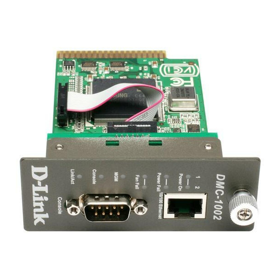
5. The default Login name and password is both “root”. Support SNMP Management The Media Converter Management Module support SNMP management. LED Indicators The LED indicators of the Switch include Power, ALERT, HTTP, ICQ, SMTP, SPEED, LINK/ACT and FDX/COL. The following shows the LED indicators for the Switch along with an explanation of each indicator. -
Page 7: Management Setting Through Web Browser
Link/Act: Lights green when link to networking Ethernet and blinks green for activity. ANAGEMENT ETTING HROUGH ROWSER Main Menu Figure (1) Main Menu System Function There are four items in System Function menu, “Software Reboot, Factory Reset, Image Update and Configuration Update. (Figure 2) Configuration There are three items in Configuration menu, “General Configuration, System Configuration and SNMP Configuration. - Page 8 Software Reboot To reboot for the software setting. 1-1-2 CPU Factory Reset This function is to set the CPU (DMC-1002) back to the default setting in case of the messy setting. 1-1-3 Factory Reset This function is to set both CPU (DMC-1002) and all system (all smart device installed in chassis) back to the default setting in case of the messy setting.
- Page 9 While the file is uploading to the system, it will appear a warning sign. (Figure 3.2) Figure (3.1) Figure (3.2)
- Page 10 1-1-5 Configuration Update Figure (4) The section is explaining how to upload and download the configure setting of the module. The Configuration Upload is to restore a setting file to the management module. The Configuration Download is to backup the setting from the management module.
- Page 11 Figure (5) Hardware revision: noted the version of the hardware. BIOS revision: noted the version of the BIOS. Firmware revision: noted the version of the firmware. Change Password: the changing of the admit password. Confirm Password: to confirm the setting of admit password. System Name: to authorize the device system name.
- Page 12 default IP is “192.168.1.1”. Subnet Mask: to set the Subnet Mask, the default is “255.255.255.0”. Default Gateway: to set the gateway address, the default is “192.168.1.254”. NOTE: After configuring the system device, need to press the save button to save the setting. 1-2-3 SNMP Configuration Figure (7)
- Page 13 Cold Start trap: to set the trap for rebooting the device (default = enable). Authentication Fail Trap: to set the warning trap when the community name of the device and workstation are different (default = enable) Power Fail Trap: to set the Power Fail Trap (default = enable).
-
Page 14: Management Setting Through Terminal Emulator
ANAGEMENT ETTING HROUGH ERMINAL MULATOR Main Menu Figure (8) System Function There are three items in System Function menu, “Software Reboot, Factory Reset, Image Update. (Figure 9) Figure (9) 2-1-1 Software Reboot To reboot for the software setting. 2-1-2 Factory Reset... - Page 15 This function is to set the device back to the default setting in case of the messy setting. 2-1-3 Image Update Figure (10) The section is to set the TFTP Server IP Address first, and the default address was set to “192.168.1.2”. The Image File can be updated by uploading the image file from the TFTP server.
- Page 16 There are four items in the Configuration menu, “General Configuration, System Configuration, Media Converter Chassis, Media Converters Status and Media Converters Setting. (Figure 11) 2-2-1 General Configuration Figure (12) Hardware revision: noted the version of the hardware. BIOS revision: noted the version of the BIOS. Firmware revision: noted the version of the firmware.
- Page 17 Figure (13) MAC Address: will show out the MAC address of the device. IP Address: to allocate an IP address for the device, the default IP is “192.168.1.1”. Subnet Mask: to set the Subnet Mask, the default is “255.255.255.0”. Default GW: to set the gateway address, the default is “192.168.1.254”.
- Page 18 Figure (14) The screen will show out the power status of the chassis system. V stands for “yes” and X stands for “No”. Plug in: indicates if Power 1 or 2 was plugged in or not. Power Fail: indicates if the Power 1 or 2 is fail or not. Fan Fail: indicates if the Fan 1 or 2 is fail or not.
- Page 19 converter. 2-2-4 Media Converters Status Figure (15.2) To control the linkage of each media converter. SNMP Configuration Figure (16) Get Community Name: to get the device community name (default = public) Set Community Name: to set the device community name (default = private).
-
Page 20: When Forgot The Password
Trap Community Name: to authorize the device trap community name (default = public). Trap Host IP Address: to set the trap host IP address (same as monitoring station IP address). Cold Start trap: to set the trap for rebooting the device (default = enable). -
Page 21: Technical Specifications
ECHNICAL PECIFICATIONS General Standards IEEE 802.3 10BASE-T; IEEE 802.3u 100BASE-TX Protocol CSMA/CD 100Mbps (Half-duplex) Data Transfer Rate 200Mbps (Full-duplex) Topology Star Network Cables 10BASE-T – 2-pair UTP Cat. 3,4,5, up to 100 m (328 ft) 100BASE-TX -- 2-pair UTP Cat. 5, up to 100 m (328 ft) Power (1 and 2) LED Indicator Power Fail (1 and 2)