
Related Manuals for Samsung SRP-350PG - SRP 350 B/W Direct Thermal Printer


Summary of Contents for Samsung SRP-350PG - SRP 350 B/W Direct Thermal Printer
-
Page 1: Table Of Contents
THERMAL RECEIPT PRINTER SRP-350 Ver.2 Series SRP-350/350S/350P/350U SRP-350G/350SG/350PG/350UG Manual SERVICE CONTENTS THERMAL RECEIT PRINTER Precaution Statements Product Specification Installation and Operation Disassembly and Assembly Maintenance and Adjustment Reference Information Special Circuit Descriptions Commands Troubleshooting Exploded Views and Parts List PCB Layout and Parts List 12. - Page 2 About Notes Precaution symbols ! " Samsung Electro-Mechanics...
- Page 3 About Copyright # Samsung Electro-Mechanics Co., Ltd. ( && & & & Samsung Electro-Mechanics Co., Ltd. SRP-350 ) April 2001. , Samsung Electro-Mechanics...
- Page 4 Overview of this Receipt Printer ! " # $ % $ & $ $ ' () Samsung Electro-Mechanics...
-
Page 5: Precaution Statements
Precaution Statements 1-1 Safety Precautions WARNING : Do not use an isolation transformer during this test Samsung Electro-Mechanics... - Page 6 WARNING: First read the "Safety Precautions" section of this manual. If some unforeseen circumstance creates a conflict between the servicing and safety precautions, always follow the safety precautions. WARNING: An electrolytic capacitor installed with the wrong polarity might explode. 1-3 Precautions for Electrostatically Sensitive Devices (ESDs) Samsung Electro-Mechanics...
- Page 7 1 Precaution Statements Samsung Electro-Mechanics...
- Page 8 1 Precaution Statements MEMO Samsung Electro-Mechanics...
-
Page 9: Product Specification
: AC 120V ~ 230V, 50Hz ~ 60Hz AC Adapter Output : DC24V5%, 2.3A Environment Temperature : 0 ~ 40 Condition humidity : 30% ~ 80% RH Weight 2.3 Kg (With Packing) Dimensions(mm) 145(W) 195(D) 146(H) Table 2-1 General Specification Samsung Electro-Mechanics... - Page 10 2 Product Specifications 2-2 Appearance 2-2-1 Printer Dimensions (mm) Figure 2-1 Printer Dimension 2-2-2 AC Adapter Dimensions (mm) 51mm 150mm 87mm Figure 2-2 AC Adapter Dimension Samsung Electro-Mechanics...
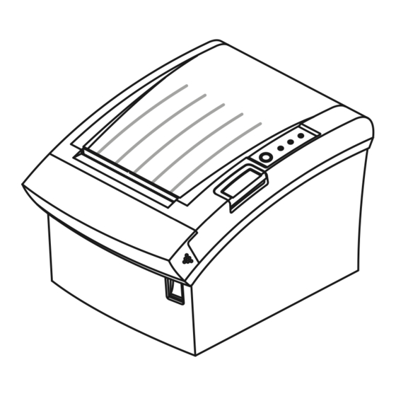
- Page 11 Cover-Open Braket Dip Switch Case-Upper 9a. RS-232C/RS-485 (Serial I/F Connector) Case-Lower IEEE-1284 (Parallel I/F Connector) Label-Control USB (USB I/F Connector) Push Button 10. Drawer Kick-Out Connector Cover-Cutter 11. DC Power Jack Power Switch Figure 2-3 Feature Location Samsung Electro-Mech anics...
-
Page 12: Thermal Printer Specifications
International Characters : 32 12 24 (Font A) (Including 2-dot spacing in horizontal) 9 17 (Font B) (Including 2-dot spacing in horizontal) Character Structure Font A is selected as the default Table2-3 Thermal Printer Character Specification Samsung Electro-Mechanics... -
Page 13: Paper Specification
: 110 Pulses / 100Km Auto Cutter : 1,000,000 Cut MCBF 37,000,000 Line Operating : 0 ~ +45 Environmental Temperature Storage : -10 ~ +50 (Except for Paper) Humidity 10% ~ 90% RH Table 2-5 Thermal Printer Reliability Specification Samsung Electro-Mechanics... -
Page 14: Printable Area
72.192 0.2mm Print Width 650 3% Average Resistance Resistance R25 : 30 5% (At 25) B Value Thermister : 3950 K 2% Temperature : -20 ~ +80 Table 2-6 TPH Specification Samsung Electro-Mechanics... -
Page 15: Other Component Specification
: 4-Phase, 48-Polarity (PM Type Bi-Polar Driver) Paper Feed Motor : 24V 10% DC Voltage Resistance : 20 at 25 per Phase Paper End Sensor Reflection Type Photo Sensor Paper Roll Near End Reflection Type Photo Sensor Sensor Table 2-8 Other Component Specification Samsung Electro-Mechanics... -
Page 16: Smps Specifications
3.0 A ~ 6.0 A Protect) S.C.P (Short Fold-Back Method Current Protect) Table 2-9 Power Adapter(SMPS) Specification 2-4-2 SMPS Output Connector Pin Number Signal Name +24 VDC Shield Frame GND Table 2-10 Power Connector Pin Description Figure 2-5 Power Connector Samsung Electro-Mechanics... -
Page 17: Interface Specifications
2-5-1-(b) RS-232C I/F Cable HOST SIDE 10 mm CONN : USER SPEC PRINTER SIDE In Case PC : D-SUB25P-MALE D-SUB25P-FEMALE D-SUB9P-FEMALE FERRITE CORE : 1 Turn (OP-118E : 18.2 12.5 25.5) Figure 2-6 RS-232C Cable Samsung Electro-Mechanics... - Page 18 The host transmits a data to the printer, after confirming this signal. When XON/XOFF flow control is selected, the host does not check this signal. Table 2-12 RS-232C Pin Description Note : Refer to the Operation Manual about the busy condition. 2-10 Samsung Electro-Mechanics...
- Page 19 Baud Rate 2400 / 4800 / 9600 / 19200 bps Data Word Length 7 Bit / 8 Bit Parity None / Even / Odd Connector DB25P Female (I/F PBA) Table2-13 RS-485 Specification Note: 2-5-2-(b) RS-485 I/F Cable Samsung Electro-Mechanics 2-11...
- Page 20 CS1 > CS2 (H) : The host computer is BUSY. CS1 < CS2 (L) : The host computer is READY. The printer transmits a data to the host, after confirming this signal. Table 2-14 RS-485 Pin Description 2-12 Samsung Electro-Mechanics...
-
Page 21: Ieee 1284 Parallel Interface
2-5-3-(a) Forward Mode Specification(Compatibility mode) Item Description Remark Data Transmission 8-Bit Parallel Synchronization External supplied nStrobe signals HandShaking nACK and Busy signals Signal Level TTL compatiable Connector Centronics 36P Table 2-15 IEEE1284 Specification 2-5-3-(b) Reverse Mode Specification (Nibble/Byte mode) Samsung Electro-Mechanics 2-13... - Page 22 AckDataReq /Data2,6 AckDataReq Printer Select Xflag /Data1,5 Xflag Host NautoFd HostBusy HostBusy Printer Logic-H Logic-H Logic-H 19~30 Host NInit Ninit nInit Printer Nfault nDataAvail /Data0,4 nDataAvail Printer DK_Status Printer Host NselectIn 1284-Active 1284-Active Table 2-16 IEEE1284 Pin Descirption 2-14 Samsung Electro-Mechanics...
-
Page 23: Usb Interface
Differential Common Mode Range : 0.8 ~ 2.5[V] Single-End Receiver Threshold : 0.8 ~ 2.0[V] Speed 12 Mbps Power Self-Powered Cable : 5m / 2m Cable & Connector Connector : B Type Other Support USB SPEC V1.1 Table2-17 USB Specification Samsung Electro-Mechanics 2-15... - Page 24 Shell Shield Drain Wire Frame Ground VBUS Host Power : DC5[V] / 500[mA] White Differential Data Line Green Differential Data Line Black Signal Ground Table 2-18 USB Pin Description 2-5-4-(c) USB I/F Cable Figure 2-10 USB Cable 2-16 Samsung Electro-Mechanics...
-
Page 25: Drawer Cable
Figure 2-11 Drawer Cable 2-6-2 Cable Connection Pin no. Description Direction Frame GND Output Drawer Kick-Out Driver Signal #1 Input Drawer Open / Close Signal +24V Drawer Kick-Out Driver Signal #2 Output Signal GND Table 2-19 Drawer Cable Connection Samsung Electro-Mechanics 2-17... - Page 26 2 Product Specifications MEMO 2-18 Samsung Electro-Mechanics...
-
Page 27: Installation And Operation
Power Connector Drawer Kick-Out Connector AC Adapter Drawer Kick-Out Cable Figure3-1 AC Adapter Installation Figure3-3 Drawer Cable Installation 3-1-2 Interface Cable Installation 3-1-4 Paper Roll Installation Interface Connector Serial Interface Cable Figure3-2 I/F Cable Installation Figure3-4 Paper Roll Installation Samsung Electro-Mechanics... -
Page 28: Wall Mount Installation
3 Installation and Operation 3-1 Installation 3-1-5 Wall Mount Installation to the Upper- Left Hole and the Upper-Right Hole inside of the printer (Figure3-5). 8. Insert the BRKT Hanger of Set to the BRKT Mount as illustrated in the Figure 3-12. Samsung Electro-Mechanics... - Page 29 3-1-5 Wall Mount Installation (Continue) Shaft Grease Plate spring Figure 3-6 Wall Mount #3 Figure 3-7 Wall Mount #4 Figure 3-8 Wall Mount #5 Figure 3-9 Wall Mount #6 Figure 3-10 Wall Mount #7 Figure 3-11 Wall Mount #8 Samsung Electro-Mechanics...
-
Page 30: Setting The Dip Switches
SW1-7 Baud rate selection Refer to the Following Table SW1-8 Table 3-1 DIP switch Setting 1 Function Transmission speed SW1 – 7 SW1 – 8 2400 baud 4800 baud 9600 baud 19200 baud Table 3-2 Baud Rate Selection Samsung Electro-Mechanics... - Page 31 Table 3-5 DIP switch Setting 1 Function Switch No. FUNCTION DEFAULT SW2-1 Emulation STAR EPSON SW2-2 Reserved SW2-3 Reserved SW2-4 Reserved SW2-5 Select Print Density Refer to the Following Table SW2-6 SW2-7 Reserved SW2-8 Reserved Table 3-6 DIP switch Setting 2 Function Samsung Electro-Mechanics...
-
Page 32: Hexadecimal Dumping
02 0D 1B 44 0A 14 1E 28 . . . D ..( 00 01 0A 41 0D 42 0A 43 . . . A . B . C 3-2-5 The Self Test Mode Samsung Electro-Mechanics... - Page 33 R S T U V W X Y Z [ \ ] ^ _ ’ a b c d e f g h i j k l m n o p q r s t u v w x y z { *** COMPLETED *** *** COMPLETED *** (A) Serial Self-Test Sheet (B) Parallel Self-Test Sheet Figure 3-7 The Self-Test Sheet Samsung Electro-Mechanics...
- Page 34 3 Installation and Operation MEMO Samsung Electro-Mechanics...
-
Page 35: Disassembly And Assembly
Foot-Rubber 4 from the printer. Scrw (3x8) Brkt Dip Switch Foot Rubber Case Lower Figure 4-1 Disassembly Case-Lower #1 1. Remove the connector wires from main PBA and sub assembly. Main Pcb Figure 4-2 Disassembly Case-Lower #2 Samsung Electro-Mechanics... -
Page 36: Case-Lower Block
Brkt Serial PCB 2 . (Parallel, 485) PCB Serial (Parallel, 485) Screw (3x6) Figure 4-3 Disassembly Case-Lower #3 1. Separate the Cover-Cable 2 from the Case- Lower 1 . Case Lower Cover Cabel Figure 4-4 Disassembly Case-Lower #4 Samsung Electro-Mechanics... -
Page 37: Disassembly And Assembly
3 during pushing the Push-Button 2 . 3. Remove the three screws 4 . 4. Separate the Manual-Cutter 5 from the Case-Upper 6 . Screw (3x4) Manual Cutter Screw (3x4) Push Button Figure 4-6 Disassembly Case-Upper #2 Samsung Electro-Mechanics... - Page 38 E-Ring Bushing Figure 4-7 Disassembly Case-Upper #3 1. Remove the Spring Hook 1 . Spring Hook 2. Remove the two screws 2 3 . 3. Separate the BRKT-Hook 4 . Brkt-Hook Screw (3x4.4) Figure 4-8 Disassembly Case-Upper #4 Samsung Electro-Mechanics...
-
Page 39: From The
4. Separate the Cutter-Blade 5 from the Fixed- Cutter 2 . 5. Remove the two screws 6 . 6. Separate the Cover-Plate 7 from the Cover- Housing 3 . Cutter Blade Cover Housing Screw (3x4) Screw (3x6) Figure 4-9 Disassembly Case-Upper #5 Samsung Electro-Mechanics... -
Page 40: Frame Block
Brkt Cover Cutter Frame Main Figure 4-10 Disassembly Frame #1 1. Remove the screws 1 . 2. Push the Heat-Sink Assembly 2 in the direction of an arrow and separate it. Heatsink Assy Screw Figure 4-11 Disassembly Frame #2 Samsung Electro-Mechanics... - Page 41 1. Remove the two screws 1 . Screw (3x8) 2. Separate the Frame-Main 2 from the BRKT PCB 3 . Frame Main 3. Separate the Power-Switch 4 from the BRKT PCB 3 . Brkt PCB Power Switch Figure 4-13 Disassembly Frame #4 Samsung Electro-Mechanics...
- Page 42 5. Remove the Washer slip 6 . And Separate the Gear - Idle 7 from the Frame Main 1 . 6. Remove the two Screw 8 . And Separate the Brkt-Hook Motor STEP 9 from the Frame -Main 1 . Screw (3x4.4) Figure 4-15 Disassembly Frame #6 Samsung Electro-Mechanics...
-
Page 43: Maintenance And Adjustment
Figure 5-2 Paper Remaining Amount for Paper Spool Diameter Figure 5-2 Paper Remaining Amount for Paper Spool Diameter Figure 5-2 Paper Remaining Amount for Paper Spool Diameter Figure 5-2 Paper Remaining Amount for Paper Spool Diameter Samsung Electro-Mechanics... - Page 44 1. Open the auto cutter cover with power ON. 2. Then turn the knob clockwise with a coin or similar tool until the buzzer beep stops. 3. Close the auto cutter cover. 4. Pull up the roll paper cover by hand. Figure 5-3 Paper Jam Samsung Electro-Mechanics...
- Page 45 Connector Electrode layer Resistor Board Base Protective layer Figure5-4 Cleaning the Printer Head Note : Never touch the thermal element with your hand. Doing so can damage the thermal element. Note : Do not scratch the Printer Head. Samsung Electro-Mechanics...
-
Page 46: Reference Information
P8.0/TA4OUT/U A10/P3.2 P8.1/TA4IN/U A9/P3.1 P8.2//INT0 P8.3//INT1 A8/P3.0 P8.4//INT2 P8.5/NMI A7/P2.7 A6/P2.6 A5/P2.5 A4/P2.4 XOUT A3/P2.3 /RESET A2/P2.2 P8.6/XCOUT A1/P2.1 P8.7/XCIN A0/P2.0 CNVSS /INT5/D15/P1.7 BYTE /INT4/D14/P1.6 P9.0/TB0IN/CLK3 /INT3/D13/P1.5 P9.1/TB1IN/SIN3 D12/P1.4 P9.2/TB2IN/SOUT3 D11/P1.3 P9.3/DA0/TB3IN D10/P1.2 P9.4/DA1/TB4IN D9/P1.1 P9.5/ANEX0/CLK4 D8/P1.0 P9.6/ANEX1/SOUT4 Samsung Electro-Mechanics... - Page 47 P4.7 /CS3 (Chip Select 3) – USB CS P10.0 Drawer Compulsory Sensing S/W P4.6 /CS2 (Chip Select 2) VREF AD Reference Voltage Input P4.5 /CS1 (Chip Select 1) AVCC +5V (VCC) P4.4 /CS0 (Chip Select 0) P9.7 DIP_C4 Samsung Electro-Mechanics...
- Page 48 Data 14 Address 0 Data 7 /RESET Data 7 Data 0 Data 6 Data 0 Data 15 Data 1 Data 5 Data 8 Data 2 Data 4 /RY/BY Data 1 /BYTE Data 3 Address 18 Data 9 Address 16 Samsung Electro-Mechanics...
- Page 49 Differential Bus Transceivers Voltage Detect System Reset IC OUTPUT DELAY CATACITOR XOUT FS741 MAX488 REF_OFF SUPPLY VOLYAGE MAX488 DRIVER MAX488 RECEIVER INPUT OPERATION DIFFERENTIAL INPUT OUTPUT 0.2 V -0.2 V < V < 0.2 V -0.2 V Samsung Electro-Mechanics...
- Page 50 OUT B SENSE PULSE TIME OUT A T1OUT MAXIM R1IN MAX232 TEA3718 R1OUT T1IN REFERENCE T2OUT T2IN COMP_INPUT R2IN R2OUT PHASE TEA3718 DRIVER TRUTH TABLE REMARK CURRENT NO CURRENT LOW CURRENT MEDIUM CURRENT MAXIUM CURRENT USB Controller : USBN9602 Samsung Electro-Mechanics...
- Page 51 FET IRFR9024 TR MMBT2222 1: Base 2: Collector 3: Emitter 1: Drain 2: Gate 3: Source 1:Base 2: Emitter 3: Collector DIODE MMBD6050L OSCILLATOR 16[MHz] 16.00MHz 1:Anode 2: N.C 3: Cathode 1:X1 2: N.C 3: N.C 4: X2 Samsung Electro-Mechanics...
-
Page 52: Special Circuit Descriptions
(+5VDC) Logic IC Driving Voltage (+24VDC) Thermal Printer Head(TPH) Voltage Table 7-1 Power Source Voltage Descriptions 7-1-1 Drawer Driving and Feed, Auto Cutter Motor Voltage : +24Vdc 7-1-2 Logic IC Driving Voltage: +5V 7-1-3 TPH Driving Voltage: +24Vdc Samsung Electro-Mechanics... -
Page 53: Reset Circuit
7 Special Circuit Descriptions 7-2 RESET Circuit FLASH RESET CHIP M51953B RESET OUT Figure 7-2 Reset Block Diagram Power-Off Power-On 4.3V /RESET 45ms Figure 7-3 Reset Waveform Samsung Electro-Mechanics... -
Page 54: Buzzer And Cash Drawer Circuits
Figure 7-4 Buzzer Block Diagram 7-3-4 Cash Drawer Driving Circuit Caution: make sure that the Cash Drawer solenoid resistance is more than 20 +24V DRAWER DWR1 / 2 DRIVING SOLENOID CIRCUIT DWR_COMP1 COMPULSORY [DRAWER] +24V 70ms Figure 7-5 Cash Drawer Block Diagram Samsung Electro-Mechanics... - Page 55 Table 7-2 I/F PBA Detector Descriptions I/F SEL is executed only one time I/F SEL(OUT) after RESET. C1 (IN) C2 (IN) C3 (IN) C1,C2,C3 = H,L,L IEEE1284 PBA Table 7-6 I/F PBA Detector Block Diagram Samsung Electro-Mechanics...
- Page 56 PRT transmits a data Printer checks whether the host is BUSY. RECEIVE (PRINTER) DSR() PRT BUSY PRT BUSY PRT NOT BUSY PC(HOST) PRINTER TXD() HOST transmits a data HOST checks whether the Printer is BUSY. Figure 7-8 RS-232C Communication Waveform Samsung Electro-Mechanics...
- Page 57 DATA “L” (+)Level (+)Level Transmission a data (1 Byte) RECEIVE (PRINTER) A-B = A-B = A-B = A-B = A-B = (+)Level (5V) (-)Level (+)Level (-)Level (+)Level (-)Level (+)Level (5V) Received data (1 Byte) Figure 7-10 RS-485 Waveform Samsung Electro-Mechanics...
-
Page 58: Parallel Communication Block Diagram
7 Special Circuit Description 7-6 Parallel Communication Block Diagram Data[7:0] 74HC574 DRIVER 74HC574 DRIVER M30624FGFP CONTROL Table 7-11 IEEE-1284 Communication Block Diagram Samsung Electro-Mechanics... -
Page 59: Usb Communication Block Diagram
7 Special Circuit Descriptions 7-7 USB Communication Block Diagram Data[7:0] B Type USBN9602 Controller M30624FGFP CLOCK 48[MHz] Table 7-12 USB Communication Block Diagram Samsung Electro-Mechanics... -
Page 60: Dip Switch Circuit
R2 checks No.5~8 of DIP S/W#1. R2 (OUT) R3 checks No.1~4 of DIP S/W#2. R3 (OUT) R4 checks No.5~8 of DIP S/W#2. R4 (OUT) DIP S/W1 No.1 is ON. C1 (IN) C2 (IN) C3 (IN) C4 (IN) Figure 7-13 DIP Switch Block Diagram Samsung Electro-Mechanics... - Page 61 The content of data is same. STB2 257 ~ 512 Table 7-3 Printer Head Strobe Processing Printer Line /STB1 Strobe Circuit /STB2 M30624FGFP /LATCH Latch Register Shift Register #1 Shift Register #2 DATA THERMAL PRINTER Figure 7-14 Thermal Printer Block Diagram Samsung Electro-Mechanics 7-10...
- Page 62 256 Bits 256 Bits LATCH Printing(1~256) Printing(1~256) STB1 Printing(257~512) STB2 Data#1 and Data#2 Pins are shorted on Main PCB. So, the Data(256 Bits) are stored in both Shift Register #1 and #2. Table 7-15 Thermal Printer Timing Waveform Samsung Electro-Mechanics 7-11...
- Page 63 7 Special Circuit Descriptions MEMO Samsung Electro-Mechanics 7-12...
-
Page 64: Commands
Transmits the selected printer status specified by n in real-time, according to the following parameters : n = 1 : Transmit printer status. n = 2 : Transmit off-line status. n = 3 : Transmit error status. n = 4 : Transmit paper roll sensor status. Samsung Electro-Mechanics... - Page 65 Paper roll Near-END sensor : Paper adequate. Paper near-end is detected by the paper roll Near-END sensor. Not used. Fixed to On. Paper roll-end sensor : Paper present. Paper roll end detected by paper roll-end sensor. Not used. Fixed to Off. Samsung Electro-Mechanics...
- Page 66 Set the distance from the beginning of the line to the position at which subsequent characters are to be printed. * The distance from the beginning of the line to the print position is [(nL + nH ×256) ×(vertical or horizontal notion unit)] inches. Samsung Electro-Mechanics...
- Page 67 [Description] Turns underline mode on or off, based on the following values of n : Function 0, 48 Turns off underline mode. 1, 49 Turns on underline mode (1-dot thick). 2, 50 Turns on underline mode (2-dot thick). Samsung Electro-Mechanics...
- Page 68 0 ≤k ≤32 [Description] Sets horizontal tab positions. * n specifies the column number for setting a horizontal tab position from the beginning of the line. * k indicates the total number of horizontal tab positions to be set. Samsung Electro-Mechanics...
- Page 69 ESC M n [Name] Select character font. [Format] ASCII Decimal [Range] n = 0, 1, 48, 49 [Description] Selects character fonts. Function 0, 48 Character font A (12 ×24) selected. 1, 49 Character font B (9 ×17) selected. Samsung Electro-Mechanics...
- Page 70 Turn 90°clockwise rotation mode on/off. [Format] ASCII Decimal [Range] 0 ≤n ≤1, 48 ≤n ≤49 [Description] Turn 90°clockwise rotation mode on/off. n is used as follows : Function 0, 48 Turn off 90°clockwise rotation mode. 1, 49 Turn on 90°clockwise rotation mode. Samsung Electro-Mechanics...
- Page 71 Paper roll near-end sensor disable. Paper roll near-end sensor enable. Paper roll near-end sensor disable. Paper roll near-end sensor enable. Paper roll end sensor disable. Paper roll end sensor enable. Paper roll end sensor disable. Paper roll end sensor enable. Undefined. Samsung Electro-Mechanics...
- Page 72 = 0, 1, 48, 49 0 ≤t1 ≤255, 0 ≤t2 ≤255 [Description] Outputs the pulse specified by t1 and t2 to connector pin m as follows. Connector pin 0, 48 Drawer kick-out connector pin 2 1, 49 Drawer kick-out connector pin 5 Samsung Electro-Mechanics...
- Page 73 Horizontal Dot Density (DPI) 0, 48 Normal 1, 49 Double-width 2, 50 Double-height 3, 51 Quadruple * n is the number of the NV bit image (defined using the FS q command). * m specifies the bit image mode. 8-10 Samsung Electro-Mechanics...
- Page 74 0 ≤nL ≤255, 0 ≤nH ≤255 [Description] * Sets the absolute vertical print starting position for buffer character data in page mode. * This command sets the absolute print position to [(nL + nH ×256) ×(vertical or horizontal motion unit)] inches. Samsung Electro-Mechanics 8-11...
- Page 75 : Printing position 0, 48 Not printed. 1, 49 Above bar code. 2, 50 Below bar code. 3, 51 Both above and below the bar code. * HRI indicates Human Readable Interpretation. 8-12 Samsung Electro-Mechanics...
- Page 76 The value of m selects the mode as follows : Print mode 0, 1, 49 Partial cut (one point left uncut) Feeds paper (cutting position + [nX(vertical motion unit)]), and cuts the paper partially (one point left uncut). Samsung Electro-Mechanics 8-13...
- Page 77 After waiting for the period specified by t, the PAPER OUT LED indicators blink and the printer waits for the FEED button to be pressed. After the button is pressed, the printer executes the macro once. The printer repeats the operation r times. 8-14 Samsung Electro-Mechanics...
- Page 78 Not used. Fixed to On. Cover is closed. Cover is open. Paper is not being fed by using the PAPER FEED button. Paper is being fed by using the PAPER FEED button. Not used. Fixed to Off. Samsung Electro-Mechanics 8-15...
- Page 79 = 0, 1, 48, 49 [Description] Selects a font for the HRI characters used when printing a bar code. n selects a font from the following table : Font 0, 48 Font A (12 ×24) 1, 49 Font B (9 ×17) 8-16 Samsung Electro-Mechanics...
- Page 80 0 ≤d ≤127 73 CODE 128 1 ≤ n ≤255 0 ≤d ≤127 GS r n [Name] Transmit status. [Format] ASCII Decimal [Range] n = 1, 2, 49, 50 [Description] Transmits the status specified by n as follows. Samsung Electro-Mechanics 8-17...
- Page 81 0.423 0.423 1.129 0.564 0.564 1.411 0.706 0.706 1.834 0.847 0.847 2.258 * Multi-level bar codes are as follows : UPC-A, UPC-E, JAN13(EAN13), JAN8(EAN8), CODE93, CODE128. * Binary-level bar codes are as follows : CODE39, ITF, CODABAR. 8-18 Samsung Electro-Mechanics...
-
Page 82: Troubleshooting
3. Check the related Circuit & Pattern Power V (+24V) Ok? 1. Check the TR(Q3, Q4) 2. Check the On/Off Signal on CPU Power VCC (+5V) Ok? 1. Check the IC34063(U5) 2. Check the related Circuit & Pattern 3. Check the generated Frequency Samsung Electro-Mechanics... -
Page 83: System Problem
2. Check the related Circuit & Pattern on PCB 3. Program downLoad again SRAM 1. Check the/CS Signal 2. Check the SRAM 3. Check the Addr/Data Pattern 1. Check the Main Clock(16.00MHz) 2. Check the Addr/Data Line Pattern 3. Check the Main PBA Samsung Electro-Mechanics... -
Page 84: Panel Pba And Sensor Problem
2. Check the TR(Q7) and the reated Pattern 3. Check the Harness 4. Check and Replace the P_End Sensor Near End 1. Check the Near-End S/W Signal on Main PBA 2. Check the Harness 3. Check and Replace the Micro S/W Samsung Electro-Mechanics... - Page 85 2. Check the Current Control Signals(StepI0, StepI1) on CPU 3. Check the Output Signal of U9, U11(TEA3718) 4. Check Auto Cutter Assembly(Motor, Cutter...) 5. Check the Harness 6. Check the Step Motor and the related Circuit & Pattern Samsung Electro-Mechanics...
-
Page 86: Auto Cutter And Drawer Problem
2. Check the Drawer Signals on CPU(P1.6/P1.7) 3. Check the related circuit & Component D560(Q1, Q2) 4. Check the Solenoid in the Drawer Compulsory Failure? 1. Check the Compulsory Harness & Connector 2. Check the Micro switch in the Drawer Samsung Electro-Mechanics... - Page 87 4. Check the related Circuit & Pattern I/F PBA Select Problem I/F PBA Select Ok? 1. Check the Output Signal(I/F Sel) on CPU 2. Check the Diode on I/F PBA 3. Check the Input Signal(DIP C1~C4) 4. Check the related Circuit & Pattern Samsung Electro-Mechanics...
- Page 88 5. Check whether Signal is affected by the Cable Noise Handshake 1. Check the connection of the H/W handshaking Line and Other side(DTR/DSR) 2. Check the I/F Cable whether it is open or short 3. Confirm the H/W handshaking Protocol Samsung Electro-Mechanics...
- Page 89 Handshake 1. Check the connection of the H/W handshaking Line and Other side(DR1,2/CS1,2) 2. Check the I/F Cable whether it is open or short 3. Confirm the H/W handshaking Protocol 4. Check the Voltage Level of each Line Samsung Electro-Mechanics...
- Page 90 1. Check the Control Lines(CS3, WR, P_WR) 2. Check the 1284 Control, Status Data Line 3. Check the Signal of ICs(U1, U3, U6) 4. Check the 1284 Cable whether it is open or shortl 5. Check the related Circuit and Pattern on I/F PBA Samsung Electro-Mechanics...
-
Page 91: Usb Communication Problem
2. Check the D+ whether it is Pull up to V3.3 3. Check the Host whether it works correctly 4. Check the USB Cable whether it is open or short 5. Check the related Circuit and Pattern on I/F PBA 9-10 Samsung Electro-Mechanics... -
Page 92: Exploded Views And Parts List
10 Exploded Views and Parts List 10-1 Main Set (V2.1) 10-1-1 Whole Set Exploded View A. ASS'Y CASE-UPPER B. ASS'Y FRAME-MAIN 13-1 10-1 C. ASS'Y CASE-LOWER 34 33 86mm 46mm 45mm 51mm Samsung Electro-Mech anics 10-1... -
Page 93: Parts List
KH04-00001A SHAFT WALL MOUNT;STS304,Φ4,L12.9 JE72-00207A PCT-SILP WASHER;SRP-350,PET,T0.5 JE70-00286E ICT-SHAFT HINGE;SRP-350,STS304,4 JE61-00013D SPRING-TENSHION;SRP-350,SUS304-WPA JE61-00013D SPRING-TENSHION;SRP-350,SUS304-WPA JE68-00109T LABEL(R)-WARNING,350,TETRON,T0.175,SILVER ENGLISH JE68-00115C LABEL(P)-WARNING COVER,TETRON,T0.05,SIL KOREA JE70-00287E IPR-COVER PLATE;SRP-350,SPCC,-,T1.0,NI 6002-000315 SCREW-TAPPING;PH,+,2,M3,L4,ZPC(YEL), JE70-00290E IPR-MANUAL CUTTER;SRP-350,SUS301,T0.4 JE72-00210F PMO-CASE UPPER;SRP-350,-,ABS,IV16,-,V0,- I-VORY JE72-00210G PMO-CASE UPPER;SRP-350,-,ABS,D-GRAY,V0 D-GRAY 10-2 Samsung Electro-Mechanics... - Page 94 AP04-00003A ASS'Y-PBA COVER JE72-00210S PMO-LEVER RELEASE;SRP-350,-,POM,BLACK AP04-00004A ASS'Y-PBA FUNCTION JE39-00053N CBF HARNESS-COVER SENSOR,1061,1.30MM,175MM JE72-00210R PMO-PUSH BUTTON;SRP-350,C75064,ABS,HB 6002-000319 SCREW-TAPPING;PH,+,2,M3,L8,ZPC(YEL), JE72-00210Z PMO-GUIDE BUTTON;SRP-350,-,HIPS,BLACK,V0 JE61-00013E SPRING-RELEASE;SRP-350,SWP,5.5,5,31. JE39-00053M CBF HARNESS-LED,1061,1.30MM,150MM AP04-00005A ASS'Y-PBA PAPER END 6002-001045 SCREW-TAPPING;BH,+,2,M2,L5,ZPC(YEL), JE68-00109B LABEL(P)-PROTECT TPH,350,MOJO,0.05T,W156,L301 JE70-00292A PLATE SPRING:SUS301 3/4H,T0.6 Samsung Electro-Mechanics 10-3...
- Page 95 I-VORY JE68-00122B LABEL-LOGO,TETRON,T0.05,W35,L8,IVORY D-GRAY JF01-000070 POWER COVER MANUAL JE72-00229B PMO-POWER COVER,ABS V0,IVORY,W21xL15xH4.3 I-VORY JE72-00229A PMO-POWER COVER,ABS V0,D-GRAY,W21xL15xH4.3 D-GRAY JE69-00105D BAG PE,,LDPE,T0.05,90,70 JE68-00111D LABEL(R)-RATING,350,TETRON,T0.175,SILVER ENGLISH JE68-00115E LABEL(R)-RATING,350,TETRON,T0.175,SILVER KOREA JE70-00287H IPR-BRKT UPPER COVER;SRP-350,SECC,T1.0 KC04-00019A SCREW;M3X4,TAPTITE,ZPC(WHITE) JE70-00290G IPR-BRKT POWER S/W;SRP-350,SECC,T1.0 10-4 Samsung Electro-Mechanics...
- Page 96 JE44-00008A SMPS-SRP350, PW105KA2400F04 JE44-00010B SMPS-SRP350, N60-240100-161 JE44-00010A SMPS-SRP350, AD5024MP JE39-00060A CBF LINE CORD,POWER,250MM,BLK EUROPE JE39-00058B CBF LINE CORD,POWER,250MM,BLK U.S.A JE39-00059A CBF LINE CORD,POWER,250MM,BLK JE39-00064E CBF LINE CORD,POWER,250MM,BLK CHINESE JE39-00059C CBF LINE CORD,POWER,250MM,BLK AUSTRALIA JE39-00059D CBF LINE CORD,POWER,250MM,BLK AFRICA Samsung Electro-Mechanics 10-5...
-
Page 97: Pcb Layout And Parts List
11 PCB Layout and Parts List 11-1 Main PCB Layout 11-1-1 Component Side Samsung Electro-Mechanics 11-1... - Page 98 11 PCB Layout and Parts List 11-1 Main PCB Layout 11-1-1 Component Side Samsung Electro-Mechanics 11-2...
- Page 99 11 PCB Layout and Parts List 11-1 Main PCB Layout 11-1-2 Solder Side Samsung Electro-Mechanics 11-3...
- Page 100 11 PCB Layout and Parts List 11-1 Main PCB Layout 11-1-2 Solder Side 11-4 Samsung Electro-Mechanics...
- Page 101 3301-000344 CORE-FERRITE BEAD;AA,-,3.5x0.6x6.5mm BD1,BD2 3407-000177 SWITCH-DIP;5V,10mA,SLIDE,SPST SW1,SW2 3601-000261 FUSE-CARTRIDGE;250V,3.15A,TIME-LAG,G FUSE 3602-000001 FUSE-CLIP;-,-,30mohm 3702-001124 CONNECTOR-RIBBON;34P,MALE,ANGLE,AUF 3706-001044 CONNECTOR-CIRCULAR;FEMALE,3P,#24 3708-000217 CONNECTOR-FPC/FC/PIC;21P,1.25mm,STRA CN13 3711-000470 CONNECTOR-HEADER;3WALL,4P,1R,2mm,STR 3711-000961 CONNECTOR-HEADER;BOX,4P,1R,2.5mm,STR CN11 3711-001097 CONNECTOR-HEADER;BOX,7P,1R,2.5mm,STR CN10 3711-003968 CONNECTOR-HEADER;BOX,3P,1R,2.5mm,STR CN7,CN12 3711-003969 CONNECTOR-HEADER;BOX,2P,1R,2.5mm,STR 3722-001034 JACK-MODULAR;6P/6C,-,-,ANGLE,-,-,GRA JE27-00002A COIL FILTER-;ER-350,140 UH,-,- L1,L20 Samsung Electro-Mechanics 11-5...
- Page 102 C201,C15,C13,C12,C11,C249,C247,C233, C234,C235,C236,C250,C226,C228,C232, C203 2203-000595 C-CERAMIC,CHIP;0.22nF,5%,50V,NP0,TP, C248,C210,C256,C257 C255,C238,C237,C230,C258,C9,C7,C6,C227, 2203-000634 C-CERAMIC,CHIP;0.022nF,5%,50V,NP0,TP C239,C259,C260 2203-000748 C-CERAMIC,CHIP;0.03nF,5%,50V,NP0,TP, C244 2203-000938 C-CERAMIC,CHIP;0.47nF,5%,50V,NP0,TP, C240 2203-001223 C-CERAMIC,CHIP;0.82nF,10%,50V,X7R,TP C253,C242,C231,C229 C223,C241,C216,C261,C251, 2203-001801 C-CERAMIC,CHIP;10nF,10%,100V,X7R,TP, C262,C222,C205,C214,C211 2801-003315 CRYSTAL-SMD;16MHz,50ppm,28-AAV,16pF, OSC1 L4,L205,L208,L3,L14,L13,L12,L11,L10,L204, 3301-000325 CORE-FERRITE BEAD;AB,60ohm,3.2x2.5x1.3 L203,L202,L201,L16,L210,L206,L209,L2,L207, L18,L15,L9,L8,L7,L6,L5 4701-001020 FREQ-ATTENUATOR;5-80MHz,15dB,-,0.03W K304-00006A PCB-MINI PRINTER;SRP-350,FR-4,2L,-,T 11-6 Samsung Electro-Mechanics...
- Page 103 LED;CBI-ANGLE,GRN,5mm,560nm LED3 0601-000204 LED;CBI-ANGLE,RED,5mm,655nm LED1,LED2 R6,R5,R4,R3,R1, 2007-000931 R-CHIP;470OHM,5%,1/10W,DA,TP,2012 R2,R252 2203-000192 C-CERAMIC,CHIP;100nF,+80-20%,50V,Y5V 2203-001801 C-CERAMIC,CHIP;10nF,10%,100V,X7R,TP, 3404-001100 SWITCH-TACT;12V,50MA,160GF,8.5X10.5X 3711-001097 CONNECTOR-HEADER;BOX,7P,1R,2.5mm,STR 3711-003968 CONNECTOR-HEADER;BOX,3P,1R,2.5mm,STR AP04-00036A ASS'Y-PBA PAPER END SENSOR 0604-001157 PHOTO-INTERRUPTER;TR,-,75MW,AXIAL-4, 2007-00026 R-CHIP;200OHM,5%,1/10W,DA,TP,2012 R202 2007-000941 R-CHIP;47KOHM,5%,1/10W,DA,TP,2012 R201 JE39-00053L CBF HARNESS-P_END SENSOR;SRP-350,UL1 CN201 Samsung Electro-Mechanics 11-7...
- Page 104 11 PCB Layout and Parts List 11-2 RS-232C Serial I/F PCB Layout 11-2-1 Component and Solder Side (New) Samsung Electro-Mechanics 11-8...
- Page 105 C-CERAMIC,CHIP 0.47nF,5%,50V,NPO C6 C7 C8 C9 2402-000168 C-AL,SMD 100uF,16V,20%8.3*8.3 3301-000325 CORE-FERRITE BEAD AB,3.2*2.5*1.3,60ohm L1 L2 L3 L4 3701-000154 CONNECTOR-D SUB 25P,2R,FEMALE,ANGLE K204-00007A DIP SWITCH 2P 3702-001125 CONNECTOR-RIBBON 34P,FEMALE,ANGLE,AU 6021-000222 NUT-HEXAGON JE41-00467C PCB-RS232 SRP-350,FR-4,80*40 JE70-00290D IPR-BRKT RS232 SRP-270/350 Samsung Electro-Mechanics 11-9...
- Page 106 C6 C7 C8 C9 2402-000168 C-AL,SMD 100uF,16V,20%8.3*8.3 2402-000170 C-AL,SMD 1uF,50V,20%4.3*4.3*5 C2 C3 C4 C5 3301-000325 CORE-FERRITE BEAD AB,3.2*2.5*1.3,60ohm L1 L2 L3 L4 3701-000154 CONNECTOR-D SUB 25P,2R,FEMALE,ANGLE 3702-001125 CONNECTOR-RIBBON 34P,FEMALE,ANGLE,AU 6021-000222 NUT-HEXAGON JE41-00467C PCB-RS232 SRP-350,FR-4,80*40 JE70-00290D IPR-BRKT RS232 SRP-270/350 Samsung Electro-Mechanics 11-10...
- Page 107 2007-000300 R-CHIP 10KOHM,5%,1/10W,DA,TP,2012 R5 R6 R7 R8 2007-000766 R-CHIP 330OHM,5%,1/10W,DA,TP,2012 R9 R10 R11 R12 2203-000192 C-CERAMIC,CHIP 100nF,+80-20%,50V,Y5V,TP,2012, C2 C3 2402-000168 C-AL,SMD 100uF,20%,16V,GP,TP,8.3x8.3x6.3mm 3701-000154 CONNECTOR-DSUB 25P,2R,FEMALE,ANGLE,AU 3702-001125 CONNECTOR-RIBBON 34P,FEMALE,ANGLE,AUF JE41-00467D PCB PCB-RS485,FR-4 6021-000222 NUT-HEXAGON 2C,M3,ZPC(YEL),SM20C JE70-00290C IPR-BRKT RS232 Samsung Electro-Mechanics 11-11...
- Page 108 11 PCB Layout and Parts List 11-4 IEEE 1284 Parallel I/F PCB 11-4-1 Component and Solder Side (New) 11-12 Samsung Electro-Mechanics...
- Page 109 C9 C19 C20 C21 C22 2203-000938 C-CERAMIC,CHIP,0.47nF,5%,50V,NPO C23 C24 C25 C26 C29 K804-00028A C-CERAMIC,CHIP,6.8nF,5%,51V,NPO 2203-001801 C-CERAMIC,CHIP 10nF,10%,100V,X7R C8 C28 2402-000168 C-AL,SMD 100uF,16V,20%8.3*8.3 3301-000325 CORE-FERRITE BEAD AB,3.2*2.5*1.3,60ohm 3702-000118 CONNECTOR-RIBBON 3702-001125 CONNECTOR-RIBBON 34P,FEMALE,ANGLE 6001-000568 SCREW M3X8 JE41-00469A PCB-IEEE1284 SRP-350,FR-4,T1.6 JE70-00290B IPR-BRKT PARALLEL IEEE1284 11-13 Samsung Electro-Mechanics...
- Page 110 C9 C19 C20 C21 C22 2203-000938 C-CERAMIC,CHIP,0.47nF,5%,50V,NPO C23 C24 C25 C26 C29 2203-001801 C-CERAMIC,CHIP 10nF,10%,100V,X7R C8 C27 C28 2402-000168 C-AL,SMD 100uF,16V,20%8.3*8.3 3301-000325 CORE-FERRITE BEAD AB,3.2*2.5*1.3,60ohm 3702-000118 CONNECTOR-RIBBON 3702-001125 CONNECTOR-RIBBON 34P,FEMALE,ANGLE 6001-000568 SCREW M3X8 JE41-00469A PCB-IEEE1284 SRP-350,FR-4,T1.6 JE70-00290B IPR-BRKT PARALLEL IEEE1284 11-14 Samsung Electro-Mechanics...
- Page 111 L2 L3 L4 L5 L6 L7 3301-000317 CORE-FERRITE BEAD AB,2x1.25x0.9mm,CIM21J121NES L8 L9 L10 3301-001117 CORE-FERRITE BEAD AB,125ohm,1500mA,TR,0.05ohm L12 L13 3702-001125 CONNECTOR-RIBBON 34P,FEMALE,ANGLE,AUF 3722-001101 JACK-USB 4P/1C B,8.38MM,AU,IVR,#22-28 4701-001020 IC-FREQ-ATTENUATOR 5-80MHz,15dB,-,0.03W JE41-00467E PCB-USB,FR-4,2L,T1.6 JE70-00290P IPR-BRKT USB,SECC,1.0 6003-000261 SCREW M3X6,TAPTITE 11-15 Samsung Electro-Mechanics...
-
Page 112: Block Diagram
HEAD HEAD DIP SENSING PAPER FEED PAPER FEED SWITCH CIRCUIT MOTOR MOTOR DRAWER & DRAWER LED & BOTTON PANEL BOARD C O M P U L S O R Y CIRCUIT SENSER CLOCK CIRCUIT (EMI) CLOCK (16.0MHz) Samsung Electro-Mechanics 12-1... - Page 113 12 Block Diagram MEMO 12-2 Samsung Electro-Mechanics...
-
Page 114: Wiring Diagram
P_End Sensor CN12 SENSOR CN13 CN11 21 19 17 15 13 11 1 2 3 4 1 2 3 4 20 18 16 14 12 10 Refer to the Schematic Diagram PRINTER AUTO FEED MECHANISM CUTTER MOTOR Samsung Electro-Mechanics 13-1... - Page 115 13 Wiring Diagram MEMO Samsung Electro-Mechanics 13-2...
- Page 116 1 4 Schematic Diagrams 14-1 Main Circuit Diagrams Samsung Electro-Mechanics 14-1...
-
Page 117: Schematic Diagrams
14 Schematic Diagrams Samsung Electro-Mechanics 14-2... - Page 118 14 Schematic Diagrams Samsung Electro-Mechanics 14-3...
- Page 119 14 Schematic Diagrams Samsung Electro-Mechanics 14-4...
- Page 120 14 Schematic Diagrams Samsung Electro-Mechanics 14-5...
- Page 121 14 Schematic Diagrams Samsung Electro-Mechanics 14-6...
- Page 122 14 Schematic Diagrams Samsung Electro-Mechanics 14-7...
- Page 123 14 Schematic Diagrams Samsung Electro-Mechanics 14-8...
- Page 124 14 Schematic Diagrams Samsung Electro-Mechanics 14-9...
- Page 125 ELECTRO-MECHANICS © SAMSUNG ELECTRO-MECHANICS Co.,Ltd. January. 2004 Printed in Korea.