Panasonic AVHS400N - MULTI FORMAT LIVE SWITCHER Operating Instructions Manual
Multi-format live switcher
Hide thumbs
Also See for AVHS400N - MULTI FORMAT LIVE SWITCHER:
- Operating instructions manual (68 pages)
Table of Contents
Quick Links
Before operating this product, please read the instructions carefully and save this manual for
future use.
Printed in Japan
POWER
ALARM
F1
F2
F3
AMB:FILL / GRN:SOURCE
KEY
DSK
PinP
AUX
CLN
PVW
AUX BUS DELEGATION
AUX SOURCE
AUX
PGM/A
1
2
3
4
5
6
PST/B
Operating Instructions
Multi-format Live Switcher
Model No.
1
2
TIME
WIPE
4
5
KEY
CHR KEY
7
8
F4
F5
DSK
PinP
10
11
MEMORY
XPT
PGM
1
2
USER
WIPE PATTERN / FUNCTION
MIX
WIPE
BKGD
KEY
MIX
WIPE
7
8
9
10
CUT
AUTO
AV-HS400N
Multi-format Live Switcher AV-HS400
PAGE
3
WIPE
SQ
SL
3D
COLOR
Z
6
ON
FREEZE
BKGD PATT
POSITIONER
9
IN/OUT
KEY PATT
12
SYSTEM
FUNC
N/R
R
WIPE DIRECTION
FTB
ON
PinP
DSK
VQTB0308-3
Table of Contents

Related Manuals for Panasonic AVHS400N - MULTI FORMAT LIVE SWITCHER


Summary of Contents for Panasonic AVHS400N - MULTI FORMAT LIVE SWITCHER
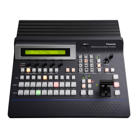
- Page 1 Operating Instructions Multi-format Live Switcher AV-HS400N Model No. Multi-format Live Switcher AV-HS400 PAGE WIPE TIME WIPE COLOR CHR KEY FREEZE BKGD PATT POWER POSITIONER ALARM AMB:FILL / GRN:SOURCE PinP IN/OUT KEY PATT MEMORY SYSTEM PinP FUNC AUX BUS DELEGATION AUX SOURCE USER WIPE PATTERN / FUNCTION WIPE DIRECTION...
-
Page 2: Safety Precautions
Safety precautions CAUTION: CAUTION TO REDUCE THE RISK OF FIRE OR SHOCK RISK OF ELECTRIC SHOCK HAZARD AND ANNOYING INTERFERENCE, DO NOT OPEN USE THE RECOMMENDED ACCESSORIES ONLY. CAUTION: TO REDUCE THE RISK OF ELECTRIC SHOCK, DO NOT REMOVE COVER (OR BACK). NO USER SERVICEABLE PARTS INSIDE. -
Page 3: Important Safety Instructions
Safety precautions IMPORTANT SAFETY INSTRUCTIONS Read these operating instructions carefully before using the unit. Follow the safety instructions on the unit and the applicable safety instructions listed below. Keep these operating instructions handy for future reference. 1) Read these instructions. 10) Protect the power cord form being walked on or pinched particularly at plugs, convenience ) Keep these instructions. -
Page 4: Table Of Contents
Contents Description ..........6 3-4. PinP (picture in picture) ........37 3-4-1. Selecting the PinP material ......37 Features ............. 6 3-4-. PinP transitions .........37 3-4-3. PinP preview ..........37 Precautions for use ........7 3-4-4. PinP adjustments ........38 3-4-5. PinP decorations ........39 1. - Page 5 Contents 4. Input/output signal settings....56 6. External interfaces ......82 4-1. Setting the SDI input signals and analog input 6-1. RS-4 connector ...........8 signals .............56 6-. GPI connector ..........83 4-1-1. Setting the frame synchronizer ....56 6-3. Tally connector..........84 4-1-. Setting the input mode ......57 4-1-3.
-
Page 6: Description
Description This is a 1 ME digital video switcher which supports a multiple number of HD and SD formats. Despite its compact dimensions, the video switcher comes standard with 4 input connectors and can support 8 input connectors when an option board is used. It also has a multi-view display function that allows split-screen display with up to 10 screens. -
Page 7: Precautions For Use
Precautions for use Handle carefully. Do not drop the product, or subject it to strong shock or vibration. Do not carry or move the product by the fader lever. This is important to prevent trouble. Use the product in an ambient temperature of 32 °F to 104 °F (0 °C to 40 °C). Avoid using the product at a cold place below 3 °F (0 °C) or at a hot place above 104 °F (40 °C) because extremely low or high temperature will adversely affect the parts inside. -
Page 8: Functions In Each Area
1. Functions in each area 1-1. Control panel Wipe pattern area LCD menu area SD memory card area User button area Positioner area Multi-format Live Switcher AV-HS400 PAGE WIPE TIME WIPE COLOR CHR KEY FREEZE BKGD PATT POWER POSITIONER ALARM ... -
Page 9: Crosspoint Area
1. Functions in each area 1-2. Crosspoint area AMB:FILL / GRN:SOURCE PinP AUX BUS DELEGATION AUX SOURCE USER PGM/A PST/B 3 PGM/A bus crosspoint buttons [PGM/A 1 to 10] These are used to select the PGM/A bus video signals. In the case of the flip-flop system, the main line video (PGM) signals are always selected. -
Page 10: Wipe Area
1. Functions in each area 1-3. Wipe area 8 Wipe pattern selector buttons These 1 buttons are used to select the corresponding wipe patterns while the indicator of the [BKGD PATT] button (9) or KEY PATT button PAGE WIPE (9) is lighted. -
Page 11: User Button Area
1. Functions in each area 1-4. User button area USER = User buttons [USER 1, USER 2] These are used to allocate some functions of the menu settings to the USER 1 button and USER button. See 5-3-1. -
Page 12: Transition Area
1. Functions in each area 1-5. Transition area PinP IN/OUT KEY PATT MEMORY SYSTEM FUNC WIPE PATTERN / FUNCTION WIPE DIRECTION WIPE BKGD PinP WIPE AUTO >... - Page 13 1. Functions in each area D [AUTO] button This is used to automatically execute transitions (auto transition) using the transition time which has been set. During auto transition its indicator lights in amber. When the button is pressed again during auto transition, the auto transition operation is suspended, and the indicator lights in green.
-
Page 14: Lcd Menu Area
1. Functions in each area 1-6. LCD menu area POWER ALARM L LCD The setting menus are displayed on the LCD. When the [FUNC] button (;) is pressed and its indicator is lighted and then one of the wipe pattern selector buttons (8) is pressed, the setting menu is displayed. -
Page 15: Positioner Area
Do not turn off the unit’s power or eject the SD memory card while the access LED is lighted. Doing so can damage the data on the SD memory card. Concerning the recommended SD cards Use of the following SD memory cards made by Panasonic is recommended. RP-SD18BU1A RP-SD56BU1A... -
Page 16: Rear Panel Connections Area
1. Functions in each area 1-9. Rear panel connections area POWER OUTPUTS INPUTS SLOT2 SLOT2 SLOT1 SLOT1 DVI INPUTS DVI/ANALOG OUTPUTS DVI-I DVI-I DVI-I SLOT SLOT ~IN ANALOG OUTPUTS ANALOG INPUTS SLOT SLOT SDI OUTPUTS SDI INPUTS RS-422 TALLY... - Page 17 1. Functions in each area Y LAN connector [LAN] (RJ-45) (10BASE-T, 100BASE-TX) Z RS-422 interface connector [RS-422] (D-sub 9-pin, female) For details on connection, refer to “6. External interfaces”. [ Tally output connector [TALLY] (D-sub 15-pin, male) For details on connection, refer to “6. External interfaces”. \ GPI input connector [GPI] (3.5 mm diameter stereo mini jack) ...
-
Page 18: System
2. System 2-1. Configuration AV-HS400 VIDEO INPUT VIDEO OUTPUT Output Matrix INPUT1(SDI) INPUT2(SDI) INPUT 1–4 INPUT3(SDI) PGM1, 2(SDI) PGM1, 2 INPUT4(SDI) OUTPUT1(SDI) OUTPUT 1, 2 OUTPUT2(SDI) INPUT SLOT1(Option) INPUT5 OUTPUT SLOT1(Option) INPUT 5, 6 OUTPUT3 INPUT6 OUTPUT 3, 4 OUTPUT4 INPUT SLOT2(Option) INPUT7 INPUT... -
Page 19: Connections
2. System 2-2. Connections Connections when implementing gen-lock (frame synchronizer OFF) Signal Generator HD camera HD SDI HD camera HD SDI HD SDI HD SDI monitor HD camera HD SDI HD SDI HD SDI monitor HD SDI HD SDI HD SDI monitor Multi-format live switcher AV-HS400N... - Page 20 2. System Connections when not implementing gen-lock (frame synchronizer ON) • Example where the optional board is used HD Component HD component monitor HD SDI DVI or VGA HD SDI monitor DVI or VGA DVI or VGA PC monitor Multi-format live POWER OUTPUTS...
-
Page 21: Basic Operations
3. Basic operations 3-1. Background transition 3-1-1. Selecting the bus Press the crosspoint buttons to select the material which will be targeted for the background transition. By pressing these buttons, the signals are selected, and the indicators of the selected buttons light. The color in which the button indicators light differs depending on the operation status. -
Page 22: Selecting The Transition Mode
3. Basic operations 3-1-3. Selecting the transition mode Press the [BKGD] button in the transition area so that its indicator lights in amber. When the [BKGD] button and [KEY] button are pressed at the same time, both buttons are selected. Use the [MIX] and [WIPE] buttons in the transition area to select the background transition mode. -
Page 23: Wipe
3. Basic operations 3-2. Wipe 3-2-1. Selecting the wipe pattern PAGE WIPE TIME WIPE COLOR CHR KEY FREEZE BKGD PATT PinP IN/OUT KEY PATT MEMORY SYSTEM FUNC WIPE PATTERN / FUNCTION The wipe patterns which are allocated to the 1 wipe pattern buttons are used as the basis for wiping, and each button has four pages —... -
Page 24: Selecting The Wipe Direction
3. Basic operations 3-2-2. Selecting the wipe direction Operate the wipe direction selector buttons to select the wipe direction for the background transition. (The key transitions are set by the menu. The direction which is set here will not be reflected. See 3-3-3.) When the indicators are off: Wiping proceeds in the normal direction. -
Page 25: 4. Setting The Wipe Start Position
3. Basic operations 3-2-4. Setting the wipe start position Any start position can be set for wipe pattern WIPE and SQ #5. The start position has one set of values for a background pattern and another set for a key pattern. 1 Press the [FUNC] button to light its indicator, and press the [WIPE] button to display the WIPE menu. -
Page 26: 5. Modifying Wipe
3. Basic operations 3-2-5. Modifying wipe Setting the lighting effect When 3D (1, 3, 7, 9) has been selected as the wipe pattern, a lighting effect can be added. 1 Press the [FUNC] button to light its indicator, and press the [WIPE] button to display the WIPE menu. 2 Turn [F1] to display the Modify sub menu. -
Page 27: Key
3. Basic operations 3-3. Key This operation combines the background image with another image. The key definition can be adjusted, and an edge can be added to the combined image. Also available as materials besides KEY for combining with the background image are PinP (picture in picture) and DSK (downstream key). -
Page 28: Selecting The Key Type
3. Basic operations 3-3-1. Selecting the key type 1 Press the [FUNC] button to light its indicator, and press the [KEY] button to display the KEY menu. 2 Turn [F1] to display the KEY sub menu. 3 Turn [F] to select the Type item. -
Page 29: 3-3-. Selecting The Key Material
3. Basic operations 3-3-2. Selecting the key material Selecting the key fill and key source signals Press the KEY button in the AUX bus selection area, and switch the selection of the key fill signal (indicator lights in amber) and key source signal (indicator lights in green).... -
Page 30: Key Transitions
3. Basic operations 3-3-3. Key transitions WIPE 1 Select key in the transition mode. Press the [KEY] button in the transition area to light its indicator. To execute a background transition and key transition at the BKGD same time, press the [BKGD] button and [KEY] button together to turn on both indicators. -
Page 31: Key Preview
3. Basic operations 5 Execute the transition. Press the [AUTO] button to execute the transition automatically for the transition time which has been set. Alternatively, execute the transition manually by operating the fader lever. When the KEYAuto function has been assigned to the [FTB] button, the transition will be executed automatically for the transition time which has been set when the [FTB] key is pressed no matter which transition mode has been selected. -
Page 32: Adjusting The Chroma Key
3. Basic operations 3-3-6. Adjusting the chroma key These steps are taken to adjust the chroma key definition. Chroma Before proceeding with the adjustments, select “Chroma” as the Type item setting in “3-3-1. Selecting the key type.” Hue Radius Sat Radius The signal for the chroma key is created using a specific color tone as a reference. - Page 33 3. Basic operations Adjusting the chroma key. 1 Press the [FUNC] button to light its indicator, and press the [CHR KEY] button to display the CHR KEY menu. 2 Turn [F1] to display the Adjust1 sub menu, and turn [F] to [F5] to set the items.
- Page 34 3. Basic operations Making other adjustments Perform the key density and key invert settings. 1 Press the [FUNC] button to light its indicator, and press the [KEY] button to display the KEY menu. 2 Turn [F1] to display the Adjust sub menu.
-
Page 35: Key Decorations
3. Basic operations 3-3-7. Key decorations A border, shadow or other edge can be added to the key. Setting the key edge 1 Press the [FUNC] button to light its indicator, and then press the [KEY] button to display the KEY menu. -
Page 36: Masking The Key Signals
3. Basic operations 3-3-8. Masking the key signals These steps are taken to mask the key signals using the mask signal of the box pattern. 1 Press the [FUNC] button to light its indicator, and press the [KEY] button to display the KEY menu. 2 Turn [F1] to display the Mask sub menu. -
Page 37: Pinp (Picture In Picture)
3. Basic operations 3-4. PinP (picture in picture) Another image can be combined with the background image. 3-4-1. Selecting the PinP material Press the [PinP] button among the AUX bus selector buttons to light its indicator, and press one of the AUX bus crosspoint buttons 1 to 10 to select the PinP signal. -
Page 38: Pinp Adjustments
3. Basic operations 3-4-4. PinP adjustments Adjusting the PinP position and size While the PinP menu is selected, adjust the X and Y coordinates using the positioners in the positioner area, and adjust the size using the rotary encoder [Z]. Alternatively, the settings can be performed on the menus. 1 Press the [FUNC] button to light its indicator, and press the [PinP] button to display the PinP menu. -
Page 39: Pinp Decorations
3. Basic operations 3-4-5. PinP decorations A border or soft effect can be added to PinP. 1 Press the [FUNC] button to light its indicator, and press the [PinP] button to display the PinP menu. 2 Turn [F1] to display the Border sub menu. -
Page 40: Trimming Settings
3. Basic operations 3-4-6. Trimming settings 1 Press the [FUNC] button to light its indicator, and press the [PinP] button to display the PinP menu. 2 Turn [F1] to display the Trim sub menu. -
Page 41: Dsk (Downstream Key)
3. Basic operations 3-5. DSK (downstream key) Characters or other images can be combined with the background image. 3-5-1. Selecting the DSK type 1 Press the [FUNC] button to light its indicator, and press the [DSK] button to display the DSK menu. 2 Turn [F1] to display the DSK sub menu. -
Page 42: 3-5-. Selecting The Dsk Material
3. Basic operations 3-5-2. Selecting the DSK material Selecting the DSK fill signal and DSK source signal Press the [DSK] button in the AUX bus selection area to switch the selection of the DSK fill signal (indicator lights in amber) and DSK source signal (indicator lights in green).... -
Page 43: Dsk Transitions
3. Basic operations 3-5-3. DSK transitions 1 Set the duration of the transition. On the TIME menu, turn [F1] to display the DSK sub menu. As with a background transition, set the transition time. 2 When the [DSK] button in the transition area is pressed, the DSK image is combined (fade-in) for the transition time which was set. -
Page 44: Dsk Decorations
3. Basic operations 3-5-6. DSK decorations A shadow or other type of edge can be added to DSK. Setting the edge 1 Press the [FUNC] button to light its indicator, and press the [DSK] button to display the DSK menu. 2 Turn [F1] to display the Edge sub menu. -
Page 45: Ftb (Fade To Black)
3. Basic operations 3-6. FTB (fade to black) The user can fade out from a program image to the black screen or fade in to a program image from a black screen. 1 Set the duration of the transition. On the TIME menu, turn [F1] to display the FTB sub menu. As with a background transition, set the transition time. -
Page 46: Internal Color Signals
3. Basic operations 3-7. Internal color signals 3-7-1. Setting the color background The color background to be used by the bus can be set. Two methods are available: under one method the Hue (hue), Sat (color saturation) and Lum (luminance) are set, and under the other the 8 preset colors (white, yellow, cyan, green, magenta, red, blue and black) are called. -
Page 47: Freezing The Input Signals
3. Basic operations 3-8. Freezing the input signals The input signals can be frozen and used. If any of the input signals has been frozen, the freeze status display LED lights. While signals are frozen, the tally signals of the corresponding input will not be output. 3-8-1. -
Page 48: Switching The Aux Output
3. Basic operations 3-9. Switching the AUX output The user can switch the AUX output signals. The signals of any of the AUX bus crosspoint button 1 to 10, PGM (program) signals, PVW (preview) signals or CLN (clean) signals can be selected for output to the AUX bus. [PGM]: The PGM signals are output to the AUX bus. -
Page 49: Preset Memory
3. Basic operations 3-10. Preset memory Up to 10 panel settings can be stored in this memory. The table below lists the settings which are stored.Item Description of setting Initial value (factory default) A bus Crosspoint B bus KEY FILL bus...
- Page 50 3. Basic operations Item Description of setting Initial value (factory default) Chroma key reference color Hue: 354.0, Sat: 100.0, Lum: 100.0 Chroma key Extent of Y component effect (Y-Infl) Chroma key range Hue-Rad: 100.0, Sat-Rad: 50.0 Chroma key border soft effect (Soft) Chroma cancel amount (CANCEL) Marker position, size (X: 5.0, Y: 5.0, Z: 5.0)
- Page 51 3. Basic operations RECALL: This is used to recall the preset memory data and change the panel settings. 1 On the MEMORY menu, turn [F1] to display the PSMEM sub menu. 2 Turn [F], select “Recall” using the Mode item, turn [F3], and set the preset memory number using the NO.Sel item.
Page 52: Frame Memories
3. Basic operations 3-11. Frame memories Still images can be stored in the unit’s two internal frame memories for use. The still images are transferred to the frame memories through the AUX bus and an SD memory card. Conversely, the images in the frame memories can be transferred to an SD memory card. Images in the frame memories can be used as bus images by assigning FMEM1 and FMEM using the crosspoint assignment function.Page 53: Sd Memory Cards
3. Basic operations 3-12. SD memory cards The unit’s frame memory data and system data can be stored on SD memory cards. Conversely, this data can be loaded from the SD memory cards to the unit. Frame memory data (still image data): 4-bit (uncompressed) BMP (bitmap) is the only file format which is supported.Page 54: 1. Initializing The Sd Memory Cards
3. Basic operations 3-12-1. Initializing the SD memory cards In order for an SD memory card to be used in the unit, it must first be initialized by the unit. Initializing an SD memory card optimizes it and creates the dedicated directory. (All files saved on the SD memory card will be erased.) ...Page 55: 3. Loading Data From Sd Memory Cards
3. Basic operations 3-12-3. Loading data from SD memory cards 1 Insert the SD memory card on which the data is stored into the SD memory card slot. Load the file after its data has been stored in the each folder. Data stored in other folders will not be recognized by the unit.Page 56: Input/Output Signal Settings
4. Input/output signal settings 4-1. Setting the SDI input signals and analog input signals The user can set the SDI input signals and analog input signals. IN5 to IN8 can be set only when the SDI input board (optional accessory) or analog input board (optional accessory) has been connected. 4-1-1.Page 57: 4-1-. Setting The Input Mode
4. Input/output signal settings 4-1-2. Setting the input mode The mode can be set for each input only when HD has been selected as the system format. When SD is selected as the system format, the input mode is always the same as Normal. Normal: Input signals in conformity with the system format take effect.Page 58: Setting The Analog Input Gain
4. Input/output signal settings 4-1-3. Setting the analog input gain The user can set the gain when the input signals are analog signals. The setting range is ±30 steps, and the gain changes by ± dB. The amount of change in the gain when it is changed by one step is not fixed. 1 On the Input sub menu, turn [F] to select the input signals using the Signal item.Page 59: Setting The Dvi Input Signals (Option)
4. Input/output signal settings 4-3. Setting the DVI input signals (option) 4-3-1. Setting the DVI input signals The user can set the DVI input signals when the DVI input board (optional accessory) has been connected. Signals with the following resolutions can be input. If signals with any other resolution or frequency are input, the picture will turn black.- Page 60 4. Input/output signal settings
HD/1080i HD/720P SD/NTSC SD/PAL DVI format Mode 1920 1080 1280 720 720 480 720 576 Fit-V 1024×768 Fit-H Full SXGA Fit-V 1280×1024 Fit-H Full WXGA Fit-V 1280×768 Fit-H Full : Black images are inserted here. Page 61: 4-3-. Adjusting The Dvi Input Signals
4. Input/output signal settings 4-3-2. Adjusting the DVI input signals Adjust the clock/phase and position of the DVI input signals. 1 Press the [FUNC] button to light its indicator, and then press the [IN/OUT] button to display the IN/OUT menu. 2 Turn [F1] to display the DVIPhs sub menu.Page 62: Setting The Output Signals
4. Input/output signal settings 4-4. Setting the output signals 4-4-1. Types of output signals There are five output signal types: PGM, PVW, AUX, MULTI and KEYOUT. Five lines of output signals can be assigned to OUTPUT1 to 6. PGM: This is the main-line output of the switcher; images with wipe, mix, key and other effects added to them are output.Page 63: Setting The Sync Signals
4. Input/output signal settings 4-5. Setting the sync signals The sync signals to be used by the system can be selected. External sync: For synchronization with an external sync signal (gen-lock). The reference input signal is looped through and output. BBST: Black burst signal (vertical phase of 0H) BBAD: Black burst signal ( Vertical phase of 90H when the 59.94i or 59.94p format is selected;...Page 64: Adjusting The Output Signal Phase
4. Input/output signal settings 4-6. Adjusting the output signal phase The phase of the output video signals can be adjusted. 1 Press the [FUNC] button to light its indicator, and then press the [IN/OUT] button to display the IN/OUT menu. 2 Turn [F1] to display the OutPhs sub menu.- Page 65 4. Input/output signal settings
(System standard) Approx. 0.2H AVDL Range Internal Fixed DL Approx. -0.2H to +0.8H Approx. 0.2H • 1H Output (+1H) Output Phase Variable Range H Phase (–0.5H to +0.5H) + V Phase vertical (100 lines) AVDL Range Internal Fixed DL Approx. Page 66: Setting The Multi View Display
4. Input/output signal settings 4-7. Setting the multi view display The input images, program images and preview images can be output side by side on one screen on the external monitor. There are three display modes for multi view display where the screen is divided into 10 parts, 4 parts or 8 parts.- Page 67 4. Input/output signal settings 1 Press the [FUNC] button to light its indicator, and press the [IN/OUT] button to display the IN/OUT menu. 2 Turn [F1] to display the Multi sub menu.
Page 68: Setting The On-Screen Display (Osd)
4. Input/output signal settings 4-8. Setting the on-screen display (OSD) The menu screen is superimposed on the preview output or multi view display output for display. 1 Press the [FUNC] button to light its indicator, and press the [IN/OUT] button to display the IN/OUT menu. 2 Turn [F1] to display the OSD sub menu.Page 69: Setting The Dvi Output Signals (Option)
4. Input/output signal settings 4-9. Setting the DVI output signals (option) Set the DVI output signals when the DVI/analog output boards (optional accessories) have been connected. 1 Press the [FUNC] button to light its indicator, and press the [IN/OUT] button to display the IN/OUT menu. 2 Turn [F1] to display the DVIOut sub menu.Page 70: Setting The Ancillary Data
4. Input/output signal settings 4-10. Setting the ancillary data In this section, the function for allowing the ancillary data of the SDI input signals to pass through is set. If SD format signals are input while the HD format has been set as the system format, it will not be possible for their ancillary data to be passed through.Page 71: System Settings
5. System settings 5-1. Selecting the video format One system (input/output signal) video format can be selected. 1 Press the [FUNC] button to light its indicator, and then press the [SYSTEM] button to display the SYSTEM menu. 2 Turn [F1] to display the Format sub menu. 3 Turn [F], select the format using the Mode item, and press the [F] switch to enter the selection.Page 72: Setting The Crosspoints
5. System settings 5-2. Setting the crosspoints 5-2-1. Assigning signals to the crosspoints External video input signals and internally generated signals can be assigned to crosspoint buttons 1 to 10. Displaying the assignment statuses 1 Press the [FUNC] button to light its indicator, and then press the [XPT] button to display the XPT menu. 2 Turn [F1] to display the XPTStats sub menu.Page 73: Setting The Crosspoint Switching
5. System settings The table below lists the default settings. Button Signal Description BLACK Internally generated signal, black INPUT1 External video input 1: SDI INPUT External video input : SDI INPUT3 External video input 3: SDI INPUT4 External video input 4: SDI INPUT5 External video input 5: SDI, analog component and DVI INPUT6...Page 74: Button Assignments
5. System settings 5-3. Button assignments 5-3-1. Setting the user buttons The user can assign several functions which can be set using the menu items into two user buttons (USER 1 and USER ). The user buttons light in amber when the assigned function is ON and are off when the assigned function is OFF. Each time the user button is pressed, the function setting alternates between ON and OFF.Page 75: Setting The Date And Time
5. System settings 5-4. Setting the date and time The user can set the date and time to be used as the SD memory card’s time stamp. Be absolutely sure to set them when an SD memory card is to be used. ...Page 76: Network Settings
5. System settings 5-5. Network settings Proceed with the network settings to perform such tasks as updating the software version via LAN. The network initial setup is: IP address: 19.168.0.10, subnet mask: 55.55.55.0 and gateway: 0.0.0.0 (unused). When using the host computer with settings matching the network setup, it is not necessary to setup via the menu.Page 77: Other Settings
5. System settings 5-6. Other settings 5-6-1. Setting the LCD backlight The LCD backlight can be set to ON or OFF. 1 Press the [FUNC] button to light its indicator, and then press the [SYSTEM] button to display the SYSTEM menu.Page 78: Setting The Gpi
5. System settings 5-6-3. Setting the GPI The user can set the functions that are to be controlled from the GPI ports and set whether to enable the control. 1 Press the [FUNC] button to light its indicator, and press the [SYSTEM] button to display the SYSTEM menu. 2 Turn [F1] to display the GPI sub menu, and turn [F] to set the function to be controlled by the GPI port 1 using the GPI1 item.Page 79: Status Displays
5. System settings 5-7. Status displays 5-7-1. Alarm status displays These displays indicate a trouble status (alarm) in the power supply or fan. 1 Press the [FUNC] button to light its indicator, and press the [SYSTEM] button to display the SYSTEM menu. 2 Turn [F1] to display the Alarm sub menu.Page 80: 5-7-. Displaying The Version Information And Option Information
5. System settings 5-7-2. Displaying the version information and option information Information on the unit’s software and hardware versions and the statuses of the options are displayed. 1 Press the [FUNC] button to light its indicator, and press the [SYSTEM] button to display the SYSTEM menu. 2 Turn [F1] to display the MainVer sub menu.Page 81: Initialization
5. System settings 5-8. Initialization Initialization returns the set data to the factory shipment status. (The date and time data is not initialized.) 1 Press the [FUNC] button to light its indicator, and then press the [SYSTEM] button to display the SYSTEM menu.Page 82: External Interfaces
6. External interfaces This unit comes with RS-4, GPI and tally connectors to serve as external interfaces. 6-1. RS-422 connector This enables the unit to be controlled by an external device. Use it with the settings below. (D-sub 9-pin, female) Baud rate: 38400 bps Parity: Stop bit:...Page 83: Gpi Connector
6. External interfaces 6-2. GPI connector These connectors enable the unit to be controlled from an external source. Signals are input using contacts. The following types of control are exercised using the contacts as triggers. Use stereo mini plugs with a 3.5 mm diameter GPI2 COMMON for connection to the unit.Page 84: Tally Connector
6. External interfaces 6-3. Tally connector The tally connector comes with tally output, output enable, power supply or fan alarm output pins. The output signals from the tally output pins are for lighting the tally lamps, and these outputs are open collector outputs.Page 85: Setting Menu Table
7. Setting menu table A setting is entered when an item displayed (↓) is selected and then the [F1], [F], [F3], [F4] or [F5] switch is pressed. (It will not be entered unless the switch is pressed.) Sub menu Parameter 1 Parameter 2 Parameter 3 Parameter 4...- Page 86 7. Setting menu table Sub menu Parameter 1 Parameter 2 Parameter 3 Parameter 4 Menu Turn F1 to select. Turn F to select. Turn F3 to select. Turn F4 to select. Turn F5 to select. Parameter Type LumKey Fill Setting range Lum, Linear, ChrmOn, ChrmOff Bus, Matte Auto, On, Off...
- Page 87 7. Setting menu table Sub menu Parameter 1 Parameter 2 Parameter 3 Parameter 4 Menu Turn F1 to select. Turn F to select. Turn F3 to select. Turn F4 to select. Turn F5 to select. Parameter Type Fill Setting range Lum, Linear Bus, Matte On, Off...
- Page 88 7. Setting menu table Sub menu Parameter 1 Parameter 2 Parameter 3 Parameter 4 Menu Turn F1 to select. Turn F to select. Turn F3 to select. Turn F4 to select. Turn F5 to select. Mode ↓ IN/OUT Input Parameter Signal AnaGain Normal, UC,...
- Page 89 7. Setting menu table Sub menu Parameter 1 Parameter 2 Parameter 3 Parameter 4 Menu Turn F1 to select. Turn F to select. Turn F3 to select. Turn F4 to select. Turn F5 to select. Exec ↓ MEMORY PSMEM Parameter Mode NO.Sel 1 to 10...
- Page 90 7. Setting menu table Sub menu Parameter 1 Parameter 2 Parameter 3 Parameter 4 Menu Turn F1 to select. Turn F to select. Turn F3 to select. Turn F4 to select. Turn F5 to select. SYSTEM Parameter GPI1 GPI2 GPIEN 4/14 Setting range AUTO, CUT,...
Page 91: Appearance
8. Appearance Unit: inch (mm) SIGNAL TALLY RS-422 INPUTS OUTPUTS SLOT SLOT INPUTS ANALOG OUTPUTS ANALOG ~IN SLOT SLOT DVI-I DVI-I DVI-I INPUTS OUTPUTS DVI/ANALOG SLOT1 SLOT1 SLOT2 SLOT2 INPUTS OUTPUTS POWER Multi-format Live Switcher AV-HS400 PAGE WIPE TIME WIPE COLOR CHR KEY FREEZE...Page 92: Specifications And Standard Accessories
9. Specifications and standard accessories Specifications Inputs 8 video input lines (maximum) 4 standard video input lines: SDI inputs ×4 Maximum of an additional 4 video input lines as options: SDI inputs ×, analog (HD/SD) inputs ×, DVI inputs × Up to two circuit boards from among the various optional input boards (incorporating two up-converter lines) can be additionally connected.- Page 93 9. Specifications and standard accessories SDI outputs SD [SMPTE 59M standard complied with] • Output return loss More than 15 dB (5 MHz to 70 MHz) 0.8 Vp-p 10 % (75 ) • Output level • Rise time Less than 1.5 ns •...
Page 94: Standard Accessories
9. Specifications and standard accessories Standard accessories Operating instructions ..............1 Operating instructions (CD-ROM) ..........1 Power Cord ................. 1 Optional circuit boards (sold separately) SDI Input Board: AV-HS04M1 Analog Input Board: AV-HS04M DVI Input Board: AV-HS04M3 Analog Output Board: AV-HS04M4 DVI/Analog Output Board: AV-HS04M5...Page 95: Appendix (Glossary)
Appendix (glossary) Defined below are the terms used in this manual. Word Explanation AB Bus system A bus control mode. By executing a transition, the A bus and B bus signals are output to the program images alternately. Ancillary Data The auxiliary data other than the video signals which is transmitted inside the data stream of the video serial interface.- Page 96 Appendix (glossary) Word Explanation Freeze A function which continues the display of the same image, creating the impression that the image has been “frozen”. FTB [Fade to Black] This is the effect where the background image is faded out to the black screen.
- Page 97 Appendix (glossary) Word Explanation The bus which carries the program output signals after the next background [Preset Bus] transition. Preset Memory The memory in which the control panel statuses can be saved and recalled. The button selection statuses as well as the border, color and other setting information can be saved in this memory.
- Page 98 PANASONIC BROADCAST & TELEVISION SYSTEMS COMPANY UNIT COMPANY OF PANASONIC CORPORATION OF NORTH AMERICA Headquarters: 3 Panasonic Way 4E-7, Secaucus, NJ 07094 (01) 348-5300 EASTERN ZONE: 3 Panasonic Way 4E-7, Secaucus, NJ 07094 (01) 348-7196 WESTERN ZONE: 3330 Cahuenga Blvd. West, Los Angeles, CA 90068 (33) 438-3608...
Table of Contents