Quick Links
1. PRECAUTIONS IN DISASSEMBLY AND REASSEMBLY:
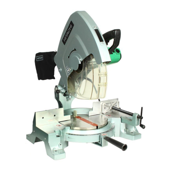
The circled numbers in the descriptions below correspond to the item numbers in the Parts List and exploded
assembly diagram.
[CAUTION] Prior to commencing disassembly (including replacement of the saw blade), ensure that the
plug is disconnected from the power source.
1-1. Disassembly:
(1) Disassembly of the Base and Turn Table:
Tools Required:
•
17 mm Box Spanner
A. After removing the M10 x 65 Bolt [120] and
M10 x 65 Screw (G) [124] which fix the Hinge
[119], the Hinge [119] and upper portions
(Gear Case, etc.) can be separated from the
main body.
B. Remove the four M10 x 40 Bolts [66] which
fix Vise (B) [82], and separate Vise (B) [82]
from the Base Ass'y [103].
C. Remove the two M6 x 16
Screws [127]. The Turn Table [87] can then
be removed by pushing it up lightly from the
rear portion of the Base Ass'y [103].
[NOTE] When removing the Hinge [119], be
very careful not to lose the D12.7 Steel
Ball [117] and Sprint (C) [118].
MODEL
-Hd. Machine
--- 1 ---
C 15FB

Related Manuals for Hitachi c15fb - 15 Amp Miter Saw No Bevel


Summary of Contents for Hitachi c15fb - 15 Amp Miter Saw No Bevel
- Page 1 MODEL C 15FB 1. PRECAUTIONS IN DISASSEMBLY AND REASSEMBLY: The circled numbers in the descriptions below correspond to the item numbers in the Parts List and exploded assembly diagram. [CAUTION] Prior to commencing disassembly (including replacement of the saw blade), ensure that the plug is disconnected from the power source.
- Page 2 (2) Disassembly of the Spring Section and the Sleeve: Tools Required: • 17 mm Wrench, 10 mm Wrench, 6 mm Hex. Bar Wrench, and Plus Screwdriver A. This step of disassembly is dangerous and requires close attention at all times. Particular caution is necessary after releasing the fixing device (paragraph D.).
- Page 3 (4) Disassembly of the Switch and Handle Section: Tools Required: • Plus Screwdriver A. When only the Switch [22] must be disassem- bled, first loosen the two M5 x 20 -Hd. Machine Screws [18] and M5 x 16 -Hd. Machine Screw [16] which fix the Handle [20]. Then loosen the two M5 x 12 -Hd.
- Page 4 (6) Disassembly of the Armature Ass'y and Stator Ass'y: Tools Required: • Plus Screwdriver, Nippers, Wooden or Plastic Hammer 1. Disassembly of the Armature Ass'y: A. Remove the Saw Cover Ass'y [3] and handle Cover [25] by following the disassembly procedures in paragraphs (3) and (4), above.
- Page 5 A. With the main switch turned ON, measure the insulation resistance between the plug prongs and exposed metal portions of the frame with a 500V DC Megohm Tester. The reading should be in excess of 7 megohms. B. If possible, a dielectric strength test should be conducted. With a Dielectric Withstand Voltage Tester, apply 4,000 volts between the plug prongs and exposed metal portions of the frame for one (1) minute with the main switch turned ON.
- Page 6 D. Finnally, ensure that the arrow mark on the Indicator [114] is properly aligned with the 0˚ setting of the Scale [89], and tighten the two M5 x 10 -Hd. Machine Screws [113]. (2) Cutting Depth Adjustment: The adjustment procedures and dimensions described below are based on the use of a 380 mm diameter Saw Blade.
-
Page 7: Wiring Diagram
1-5. Wiring Diagrams and Leadwire Arrangements: Perform wiring work as illustrated below. (1) For Products with a Dynamic Brake (115V Specification Products for the U.S. and Canada Only): WIRING DIAGRAM Cord Switch Black Armature Ass'y White Brown White Connector Stator Ass'y LEADWIRE ARRANGEMENT Noise Suppressor Connector... - Page 8 (2) For Products with a Noise Suppressor: [NOTE] The wiring diagram for products without a Noise Suppressor is the same as that illustrated below with the exception of the Noise Suppressor section. WIRING DIAGRAM Armature Stator Ass'y Ass'y Switch Noise Suppressor LEADWIRE ARRANGEMENT Vinyl Tube Black...
-
Page 9: Troubleshooting Guide
2. TROUBLESHOOTING GUIDE: The circled numbers in the descriptions below correspond to the item numbers in the Parts List and exploded assembly diagram. (All Dimensions in Millimeters) Item Phenomenon Possible Cause (s) Standard Countermeasure (s) Adjust or replace Vise (B) [82]. A. - Page 10 Cutting operation results in Saw Blade. tain very fine cutting surfaces, rough cutting surfaces (Inherent Saw Blade deflection Hitachi's TCT Saw Blade for will cause rough surfaces.) wood or aluminum (Code No. 959024) is recommended.) • B. Incorrect selection of Saw...
- Page 11 Item Phenomenon Possible Cause (s) Standard Countermeasure (s) I. The workpiece is not secure- ---- Securely fix the workpiece with Cutting operation results in ly fixed in position. Vise (A) [79]. rough cutting surfaces. J. The Turn Table is not se- ---- When performing cutting opera- curely fixed in position with the...