Table of Contents
Quick Links
Table of Contents

Related Manuals for Asus AR200


Summary of Contents for Asus AR200
- Page 1 AR200 2U RAID Storage Subsystem User Guide...
- Page 2 Product warranty or service will not be extended if: (1) the product is repaired, modified or altered, unless such repair, modification of alteration is authorized in writing by ASUS; or (2) the serial number of the product is defaced or missing.
-
Page 3: Table Of Contents
Contents ..................iii Notices ................... iv Safety information ................v About this guide ................vi ASUS contact information ............. vii AR200 specifications summary ............ viii Chapter 1: Product introduction ......... 1-1 1.1 Package contents ............... 1-2 1.1.1 Standard items ............1-2 1.1.2... -
Page 4: Notices
Notices Federal Communications Commission Statement This device complies with FCC Rules Part 15. Operation is subject to the following two conditions: • This device may not cause harmful interference, and • This device must accept any interference received including interference that may cause undesired operation. -
Page 5: Safety Information
Safety information Electrical Safety IMPORTANT • Before installing or removing signal cables, ensure that the power cables for the system unit and all attached devices are unplugged. • To prevent electrical shock hazard, disconnect the power cable from the electrical outlet before relocating the system. •... -
Page 6: About This Guide
RAID configuration. Contents This guide contains the following parts: 1. Chapter 1: System overview This chapter describes the general features of the AR200 RAID system. It includes sections on front panel and rear panel specifications. 2. Chapter 2: Hardware setup This chapter lists the hardware setup procedures that you have to perform when installing system components. -
Page 7: Asus Contact Information
Technical Support Support Fax: +1-510-608-4555 General Support: +1-502-933-8713 Web Site: www.asus.com Support Email: [email protected] ASUS COMPUTER GmbH (Germany and Austria) Address: Harkortstr. 25, 40880 Ratingen, BRD, Germany General Email: [email protected] (for marketing requests only) General Fax: +49-2102-9599-31 Technical Support Support Hotline:... -
Page 8: Ar200 Specifications Summary
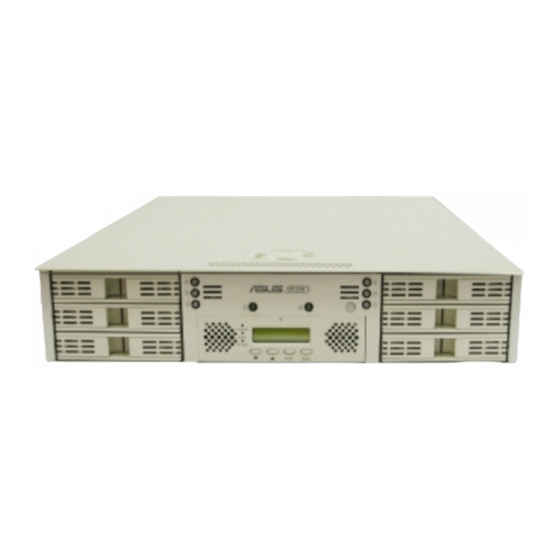
AR200 specifications summary RAID level support RAID 0, 1, 0+1, 3, 5, or JBOD RAID processor IBM PowerPC 6031 RISC CPU SCSI interface Ultra160 SCSI SCSI channel 4 SCSI channels (each channel supports 15 SCSI devices) Max. logical devices 6 devices (each logical drive can implement... - Page 9 Chapter 1 This chapter describes the general features of the AR200 RAID system. It includes sections on front panel, rear panel, and internal features of the system. ASUS AR200 RAID system...
-
Page 10: Chapter 1: Product Introduction
• Memory 128MB registered ECC SDRAM • Rackmount rails R-20 rackmount rail kit • Documentation AR200 User Guide DA3100 Hardware Manual 1.1.2 Optional items • Hard disk drives Up to six SCA-2 Ultra160 SCSI If any of the above items is damaged or missing, contact your retailer. -
Page 11: System Overview
System overview The AR200 is a 2U RAID subsystem in a 2U chassis and configured on the DA3100 RAID controller. The controller includes four channels that allow several hard disk configurations to provide more than 365GB storage capacity while keeping optimal fault tolerance and performance. -
Page 12: Internal Features
(underneath) The PCI cage is not used in this system. All the components of the AR200 RAID system are pre-installed and all the internal cables are properly connected before shipping. Do not remove any components or disconnect the cables. Chapter 2 provides details on the internal components, and describes all the cable configurations in case you accidentally detached any cable. -
Page 13: System Power Button And Leds
This LED lights up (steady green) when you apply power to the system by pressing the power button. This LED goes off when you turn off the system. Power Button The system power button is connected to the motherboard and is used for turning the system ON or OFF. ASUS AR200 RAID system... -
Page 14: Da3100 Raid Controller
128Kbps per division. Displays messages for configuration and management. Do not remove the DA3100 RAID controller unit from the AR200 system. If you encounter any problems with the controller, or if you wish to upgrade the memory, contact ASUS technical support. See page vii of this user guide for ASUS contact information. - Page 15 Chapter 2 This chapter describes the internal hardware components and provides the procedures for installing and removing hard disk drives. The SCSI cable connections is also described and illustrated in this chapter. ASUS AR200 RAID system...
-
Page 16: Chapter 2: Hardware Setup
Removing the chassis cover The AR200 chassis is a 2U form factor designed for easy assembly and disassembly, making the installation of internal components very convenient. At the top of the chassis is a rotating lock that secures the cover to the chassis. -
Page 17: Installing Scsi Hard Disk Drives
Place the SCSI hard disk drive to the hot-swap tray and secure it with four screws as shown. HDD Installation After the drive is secure on the tray, carefully insert the drive into the bay, then push the levers back in place. ASUS AR200 RAID system... -
Page 18: Cooling System
Cooling system The chassis includes an 8-cm system fan located at the front end of the PCI cage, and a 12-cm system blower (underneath a metal hood) located between the PCI cage and the power supply. The metal hood is held in place by two tabs (one on each side) that rest on the edge of the PCI cage and power supply, and two hooks attached to the rear panel. -
Page 19: Scsi Backplane Boards
Back side The back side of a backplane includes the SCSI, power, SMB, and LED connectors. The two backplane boards in the AR200 RAID system are the same but have different cable connections. The following pictures show the right and left backplane board connectors and indicate to which they are connected. -
Page 20: System Interface Board
System interface board The system interface board interconnects the backplane boards, power supply, cooling fans, and the DA3100 controller. Refer to the illustration below for the specific cables connected to the interface board. All the cables are already connected when you receive the system. You do not need to disconnect the cables when installing drives or creating a RAID configuration. -
Page 21: Da3100 Connectors
Power connector RS-232 connector (connect 4-pin power plug (to COM1 port on the from system interface board) rear panel) C connector Power connector (to SMBus connector on (connect P4 plug from system interface board) power supply) ASUS AR200 RAID system... -
Page 22: Power Supply
Power supply 2.7.1 Power cable connections The AR200 power supply unit (PSU) consists of two redundant power supply modules with five power plugs. The picture below indicates where you need to connect the PSU power plugs. SMBus connector on left backplane board... -
Page 23: System Connections
System connections 2.8.1 SCSI cabling for cluster system (MSCS) 2.8.2 Standalone system ASUS AR200 RAID system... -
Page 24: Storage Sub-System
2.8.3 Storage sub-system Refer to the following diagram to connect AR200 with AR201 (storage cabinet) when creating a storage sub-system. 2-10 Chapter 2: Hardware setup...