HP 245161-B22 - 10642 42U Rack Shock Pallet Reference Manual
10000 series rack reference guide
Hide thumbs
Also See for 245161-B22 - 10642 42U Rack Shock Pallet:
- Reference manual (70 pages) ,
- Best practices manual (48 pages) ,
- Installation instructions (4 pages)

Related Manuals for HP 245161-B22 - 10642 42U Rack Shock Pallet


Summary of Contents for HP 245161-B22 - 10642 42U Rack Shock Pallet
- Page 1 HP10000 Series Rack Reference Guide December 2002 (Second Edition) Part Number 258200-002...
- Page 2 Hewlett-Packard Company shall not be liable for technical or editorial errors or omissions contained herein. The information in this document is provided “as is” without warranty of any kind and is subject to change without notice. The warranties for HP products are set forth in the express limited warranty statements accompanying such products.
-
Page 3: Table Of Contents
Contents About This Guide Important Safety Information ................... vii Symbols on Equipment..................... vii Rack Stability........................ix Symbols in Text......................... ix Getting Help........................x Technical Support ......................x HP Website........................x Authorized Reseller..................... xi Reader’s Comments......................xi Chapter 1 Overview 10000 Series Racks......................1-2 Rack Options ........................1-3 Delivery Considerations ....................1-5 Installation Overview.......................1-5... - Page 4 Contents Space Requirements....................2-5 Power Requirements....................2-5 Grounding Requirements..................2-6 Temperature Requirements..................2-7 Airflow Requirements ....................2-8 Chapter 3 Preparing the Rack for Component Installation Required Tools ........................ 3-2 Checking the Hardware....................3-2 Removing the Rack Doors ....................3-3 Removing the Side Panels....................3-7 Stabilizing the Rack ......................
- Page 5 Contents Chapter 5 Specifications Appendix A Electrostatic Discharge Grounding Methods ......................A-2 Appendix B Transportation Instructions Transportation Methods....................B-1 Air Transport......................B-1 Land Transport ......................B-2 Sea Transport ......................B-2 Delivery Services......................B-2 Inside Rack Delivery Service................... B-2 Expedited Rack Delivery Service ................B-3 Shipping/Delivery Considerations ................
-
Page 6: About This Guide
About This Guide This guide provides step-by-step instructions for installation, and reference information for operation for the HP 10000 Series Rack. Important Safety Information Before installing this product, read the Important Safety Information document included with the server. Symbols on Equipment The following symbols may be placed on equipment to indicate the presence of potentially hazardous conditions: WARNING: This symbol, in conjunction with any of the following symbols,... - Page 7 About This Guide This symbol indicates the presence of electric shock hazards. The area contains no user or field serviceable parts. Do not open for any reason. WARNING: To reduce the risk of injury from electric shock hazards, do not open this enclosure.
-
Page 8: Rack Stability
About This Guide Rack Stability WARNING: To reduce the risk of personal injury or damage to the equipment be sure that: • The leveling jacks are extended to the floor. • The full weight of the rack rests on the leveling jacks. •... -
Page 9: Getting Help
About This Guide Getting Help If you have a problem and have exhausted the information in this guide, you can get further information and other help in the following locations. Technical Support In North America, call the HP Technical Support Phone Center at 1-800-652-6672. This service is available 24 hours a day, 7 days a week. -
Page 10: Authorized Reseller
About This Guide Authorized Reseller For the name of your nearest authorized reseller: • In the United States, call 1-800-345-1518. • In Canada, call 1-800-263-5868. • Elsewhere, see the HP website for locations and telephone numbers. Reader’s Comments HP welcomes your comments on this guide. Please send your comments and suggestions by e-mail to [email protected]. -
Page 11: Overview
Overview As computer systems have evolved in size and complexity, managing them has become a critical concern. By centralizing your equipment in a HP 10000 Series rack, the efficiency and accessibility of your system can be increased dramatically. The 10000 Series racks are designed to house rack-mountable products on industry- standard 19-inch wide rails. -
Page 12: 10000 Series Racks
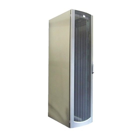
Overview 10000 Series Racks The 10000 Series racks offer the following features: • Interchangeable perforated front and split rear doors • Cable access panel on rear door • Perforated rack top with egress slot • Graphite metallic color Figure 1-1: 10000 Series racks HP 10000 Series Rack Reference Guide... -
Page 13: Rack Options
Overview Rack Options In addition to the standard racks, HP also provides rack options to complement or complete your rack solution. The following list is only a sampling of the many rack option kits available. For more information, visit the HP website at www.hp.com. - Page 14 Overview Table 1-1: Rack Options continued Option Description Cable Management D-Ring Rack Helps with cable management Option Kit 25-inch Rail Adapter Option Kit Allows the inner rack rails to accommodate third-party rack options 1U Keyboard Drawer Option Kit Holds and conceals a keyboard 100 Kilo Sliding Shelf Rack Option Allows easy access to various rack components...
-
Page 15: Delivery Considerations
Overview Delivery Considerations The following list is only a sampling of the many delivery considerations available. For more information, visit the Best Practices web page at www.hp.com. When preparing to receive palletized racks, consider the following: • The dock door at the receiving site has to accommodate the height and width of palletized racks. -
Page 16: Installation Service
Overview 9. Install the appropriate support rails and/or tray for the first rack-mountable component. 10. Install the first individual component. 11. Attach a cable management arm, if required. 12. Attach the appropriate cables and power cords to the component, being sure to adhere to all cautions and warnings. -
Page 17: Configuration Factors
Configuration Factors Before populating your new rack, it is important to plan the placement of each component. Factors of each component, such as weight, accessibility, power, temperature, and airflow requirements, affect installation order and component placement in the rack. Rack Configuration Software To help you plan your rack configuration more efficiently, HP provides Rack Builder Online, the browser-based rack configuration tool. -
Page 18: Rack Builder Online Modes Of Operation
Configuration Factors Rack Builder Online Modes of Operation The Rack Builder Online software has two modes of operation: • Help Me Build It Mode—Includes a simple interview session to help determine your rack and component needs, as well as the necessary power products and rack assembly devices needed to complete the final rack assembly. -
Page 19: Component Placement
Configuration Factors Component Placement The following rules apply to the physical placement of components in the rack: • Weight—Sort all components by weight, placing the heaviest components at the bottom of the rack. • Server Console Switch—Position the switch box on the side of the rack above the keyboard, or mount it behind the keyboard. - Page 20 Configuration Factors • Server Console Switch—If a switch box is configured, use the CPU-to-Switch cable included with the server. The standard distance between the switch box and the keyboard, monitor, and/or mouse can vary by 3-, 7-, 12-, 20- and 40-foot lengths.
-
Page 21: Optimum Environment
Configuration Factors Optimum Environment Specific requirements for space, power, temperature, and airflow must be met to provide optimum performance with minimum maintenance for your rack environment. Space Requirements When deciding where to place your rack: • At least 122 centimeters (48 inches) of clearance is needed all the way around the pallet and above the rack to allow the removal the packing materials. -
Page 22: Grounding Requirements
Configuration Factors • If a UPS is used, the load should not exceed 80 percent of the UPS’s marked electrical current rating. CAUTION: To reduce the risk of damage to the equipment, verify that all AC Voltage Selector Switches are set correctly to match your local AC line voltage (115V or 230V). -
Page 23: Temperature Requirements
Configuration Factors Temperature Requirements For safe and reliable operation of equipment, locate the system in a well-ventilated, climate-controlled environment. The HP Maximum Recommended Ambient Operating Temperature (TMRA) for most server products is 95°F (35°C). Therefore, the temperature in the room where the rack is located should not exceed 95°F (35°C). -
Page 24: Airflow Requirements
Configuration Factors Airflow Requirements HP rack-mountable products typically draw in cool air through the front and exhaust warm air out through the rear of the rack. The front door of the rack, therefore, must be adequately ventilated to allow ambient room air to enter the rack, and the rear door must be adequately ventilated to allow the warm air to escape the rack. -
Page 25: Preparing The Rack For Component Installation
Preparing the Rack for Component Installation This chapter discusses the following topics: • Required tools • Checking the hardware • Removing the rack doors • Removing the side panels • Stabilizing the rack — Standalone racks — Multiple racks • Server/Storage vs. -
Page 26: Required Tools
Preparing the Rack for Component Installation Required Tools You need the following tools to install your rack components: • Flat-bladed screwdriver • Phillips screwdrivers—#1, #2, and #3 • Torx screwdrivers—T-10, T-15, T-25, and T-30 • Adjustable wrench • Allen wrench •... -
Page 27: Removing The Rack Doors
Preparing the Rack for Component Installation Removing the Rack Doors To provide access to all sides of the rack while you are installing the various components, first remove the rack doors. If your rack has side panels, also remove them before installing mounting brackets and other hardware. To remove the rack front door: 1. - Page 28 Preparing the Rack for Component Installation 3. Lift up the top hinge pin (1). 4. Tilt the door out and lift to remove it from the bottom hinge bracket (2). 5. Lift the door out and away from the rack (3). Store the door in an upright position, taking care to protect it from damage.
- Page 29 Preparing the Rack for Component Installation To remove the rack rear doors: 1. Rotate the handle to the right (1). 2. Pull the handle to open the doors (2). Figure 3-3: Opening the rear doors HP 10000 Series Rack Reference Guide...
- Page 30 Preparing the Rack for Component Installation 3. Open the hinge brackets by pulling up on the top hinge and down on the bottom hinge for each door (1). 4. Lift the rear doors off of the hinge brackets and remove them from the rack (2). Store the doors in an upright position, taking care to protect them from damage.
-
Page 31: Removing The Side Panels
Preparing the Rack for Component Installation Removing the Side Panels To remove the side panels: 1. Unlock the two side panel locks securing the side panels to the rack (1). 2. Lift each side panel up to unhook it from the hangers bolted on the rack frame (2). -
Page 32: Stabilizing The Rack
Preparing the Rack for Component Installation Stabilizing the Rack WARNING: The rack allows you to stack computer components on a vertical rather than a horizontal plane. To reduce the risk of personal injury or damage to the equipment, you must follow these instructions carefully and heed all cautions and warnings throughout the installation instructions. - Page 33 Preparing the Rack for Component Installation Stabilizing Feet WARNING: To reduce the risk of personal injury, you must attach HP Series rack stabilizing feet to all standalone (non-bayed) racks. The Stabilizer Rack Option Kit contains three full-size and two modified stabilizing feet.
-
Page 34: Multiple Racks
Preparing the Rack for Component Installation Multiple Racks Increasing space and stability, 10000 Series racks can be bayed together by installing the Rack Option Baying Kit or the Rack Option Offset Baying Kit, depending on the series, height, and depth. •... -
Page 35: Installing Components
Installing Components IMPORTANT: It is strongly recommended that you configure your rack using the Rack Builder Online software before beginning the installation process. This chapter discusses the following topics: • General guidelines • Installation sequence • Using the template • Inserting the cage nuts •... -
Page 36: General Guidelines
Installing Components General Guidelines WARNING: To reduce the risk of personal injury, always be sure that the rack is adequately stabilized before extending a component outside the rack. A rack may become unstable if more than one component is extended for any reason. Extend only one component at a time. - Page 37 Installing Components Observe the general guidelines when loading your components: • For detailed instructions on installing a specific component or third-party hardware, see the user documentation that was shipped with the component. • See Appendix A, “Electrostatic Discharge,” before installing components into the rack.
-
Page 38: Installation Overview
Installing Components Installation Overview NOTE: The stabilizer feet should be installed prior to any component installation. IMPORTANT: The installation instructions below are for standard installations. For specific installation instructions, refer to the documentation included with your component. The following steps outline the sequence for installing rack-mountable components in a rack. -
Page 39: Using The Template
Installing Components Using the Template Use the template that was shipped with your rack-mountable component to mark the location of the mounting hardware on the mounting rails of the rack. 1. Push back the tabs (marked #) in the top of the template and place them in the correct holes in the mounting rails. -
Page 40: Inserting The Cage Nuts
Installing Components Inserting the Cage Nuts Use the cage nut insertion tool to install the cage nuts on the inside of the mounting rails. 1. Hook the bottom lip of the cage nut in the square rail perforation. 2. Insert the tip of the insertion tool through the perforation and hook the top lip of the cage nut. -
Page 41: Preparing And Installing The Rails
Installing Components Preparing and Installing the Rails IMPORTANT: The installation instructions below are for standard installations. For specific installation instructions, please refer to the documentation included with your component. There are two types of rack-mountable rails: • Adjustable fixed rails •... -
Page 42: Installing The Adjustable Fixed Rail
Installing Components Installing the Adjustable Fixed Rail 1. Insert at least one screw through the rail-mounting bracket, securing the adjustable fixed rail to the front of the rack. NOTE: After installing your components, insert at least one more screw into each adjustable rail for additional support. - Page 43 Installing Components 2. Insert at least one screw through the rail-mounting bracket and into the cage nuts installed earlier, securing the adjustable fixed rails to the rear of the rack. NOTE: After installing your components, insert at least one more screw into each adjustable rail for additional support.
-
Page 44: Preparing The Sliding Rail
Installing Components Preparing the Sliding Rail Components mounted with this type of rail are designed for frequent accessibility and/or maintenance. 1. Extend the component rail until the component rail release latch clicks (1). 2. Hold down the component rail release latch (2) and completely remove the component rail from the sliding rail assembly. - Page 45 Installing Components 3. After removing the component rails, attach the sliding rail assembly to the rack- mounting brackets. Note the orientation of the rack-mounting brackets: a. The front flange (1) has alignment tabs. b. The back flange (2) is designed to install flush against the rack. NOTE: There are eight screw holes in the standard rack-mounting brackets.
- Page 46 Installing Components 4. Note the orientation of the sliding rail assembly: a. The front of the sliding rail assembly (1) allows the inner slide to move forward on ball bearings. b. The back of the sliding rail assembly (2) has a stop for the inner slide. NOTE: While matching fronts, lay one rack-mounting bracket and one sliding rail assembly together so that the screw holes are aligned.
- Page 47 Installing Components 5. Extend the inner slide in the sliding rail assembly until the screw holes in the rack-mounting bracket and the sliding rail assembly are aligned (1). Secure the sliding rail assembly to the rack-mounting bracket by inserting one 8-32 × 3/8 screw into each of the three exposed holes, two near the rear and one near the front of the sliding rail assembly.
-
Page 48: Installing The Sliding Rails
Installing Components Installing the Sliding Rails 1. Align and secure the front of the sliding rail to the front of the rack with two M6 × 16 screws. NOTE: The tabs on the front of the sliding rails help you align them correctly with the mounting rails. -
Page 49: Preparing The Component
Installing Components 2. Align the rear of the sliding rail with the cage nuts on the rear of the rack and secure with two M6 × 16 screws. Figure 4-11: Securing the rear of the sliding rail Preparing the Component The following are general instructions for installing a typical rack-mountable component. -
Page 50: Sliding Rails
Installing Components Sliding Rails For a sliding rail installation, you need to install the component rails on the component before you can insert it into the rack. 1. Locate the component rails that you set aside when they were removed from the sliding rails earlier. -
Page 51: Cable Management Arm Bracket
Installing Components Cable Management Arm Bracket If the component uses a cable management arm, use two 6-32 × 1/4 screws to attach the bracket that supports the cable management arm to the component. NOTE: The cable management arm is installed after the component is installed into the rack. Figure 4-13: Attaching the cable management arm bracket to the component HP 10000 Series Rack Reference Guide... -
Page 52: Installing The Component
Installing Components Installing the Component After all rack-mounting hardware has been installed on the component you can insert it into the rack. WARNING: Components can be very heavy. To reduce the risk of personal injury or damage to the equipment: •... - Page 53 Installing Components 4. Press in the component rail release latches on either side of the component and slide the unit all the way back into the rack. NOTE: The first time you slide the unit into the rack, you may have to apply some pressure to loosen the ball bearings.
-
Page 54: Attaching The Cable Management Arm
Installing Components Attaching the Cable Management Arm 1. Extend the cable management arm and bend the hinged bracket to the right. 2. Use two M6 × 12 Phillips screws to attach the cable management arm to the bracket you installed on the component earlier. Figure 4-15: Attaching the cable management arm to the bracket 4-20... - Page 55 Installing Components 3. Align the screw retaining plate behind the rack-mounting rail at the rear of the rack and attach the cable management arm to the rail with two 10-32 × 5/8 screws. NOTE: As you slide the unit in and out of the front of the rack, the cable management arm collapses and extends so that the cables remain connected to the unit and stay untangled.
- Page 56 Installing Components Attaching the Cables 1. Attach any cables that need to be connected to the component. 2. To attach the power cord: a. Remove the label covering the AC power outlet. b. Set the input voltage selection switch to the appropriate position. c.
-
Page 57: Routing The Cables
Installing Components Routing the Cables 1. Bundle the cables with the cable arm extended, including the power cord. 2. Secure the cables to the cable management arm with the fasteners provided. NOTE: Leave enough slack in the cables so that you can bend the cable management arm easily. - Page 58 Installing Components 5. To remove the cable access panel: NOTE: The cable access panel can be removed from the left rear door. Rotate the handle to the right. b. Pull the handle to open the doors (1). c. Release the cable access panel hinges (2) and then unscrew the two fasteners (3).
- Page 59 Installing Components WARNING: To reduce the risk of electrical shock or damage to the equipment: • Do not disable the power cord grounding plug. The grounding plug is an important safety feature. • Plug the power cord into a grounded (earthed) electrical outlet that is easily accessible at all times.
-
Page 60: Rack Option Kits
Installing Components Rack Option Kits The following rack option kits are available for use with the HP 10000 Series rack: • Baying Rack Option Kit • Blanking Panel Rack Option Kit. • 25-inch Rail Adapter Option Kit • Cable Management D-Ring Rack Option Kit •... -
Page 61: Specifications
Specifications Table 5-1: Model 10622 Dimensions Cabinet size Height 1092 mm (43 inches) Depth 1016 mm (40 inches) Width 610 mm (24 inches) Shipping size (with Height 1346 mm (53 inches) packing materials) Depth 1219 mm (48 inches) Width 813 mm (32 inches) Weight Operating 80 kg (176 lbs) - Page 62 Specifications Table 5-2: Model 10636 Dimensions Cabinet size Height 1753 mm (69 inches) Depth 1016 mm (40 inches) Width 610 mm (24 inches) Shipping size Height 1905 mm (75 inches) (with packing materials) Depth 1219 mm (48 inches) Width 813 mm (32 inches) Weight Operating 100 kg (220 lbs)
- Page 63 Specifications Table 5-4: Model 10647 Dimensions Cabinet size Height 2286 mm (90 inches) Depth 1016 mm (40 inches) Width 610 mm (24 inches) Shipping size Height 2438 mm (96 inches) (with packing materials) Depth 1219 mm (48 inches) Width 813 mm (32 inches) Weight Operating 111 kg (245 lbs)
-
Page 64: Appendix A Electrostatic Discharge
Electrostatic Discharge To prevent damaging the system, be aware of the precautions you need to follow when setting up the system or handling parts. A discharge of static electricity from a finger or other conductor may damage system boards or other static-sensitive devices. -
Page 65: Grounding Methods
Electrostatic Discharge Grounding Methods There are several methods for grounding. Use one or more of the following methods when handling or installing electrostatic-sensitive parts: • Use a wrist strap connected by a ground cord to a grounded workstation or computer chassis. Wrist straps are flexible straps with a minimum of 1 megohm ±... -
Page 66: Transportation Instructions
Transportation Instructions NOTE: The following section is only a sampling of the many delivery considerations available. For more information, visit the Best Practices web page at www.hp.com. Transportation Methods Depending on your circumstances and time schedule, there are three transportation methods for transporting your rack: air, land, and sea. -
Page 67: Land Transport
Transportation Instructions Because of the dimensions and the weight of the racks, check with carriers for their limitations before dispatching. Land Transport All racks can be shipped by common carriers. Carriers providing air ride capabilities are preferred. Ship racks upright on their pallets. Do not lay the racks horizontally or double-stack them. -
Page 68: Expedited Rack Delivery Service
Transportation Instructions • The rack is delivered to the desired location within the facility (see “Limitations”). • Delivery service is for a single rack. Limitations • If shipping a non-integrated rack, door widths and corridors must accept a 99-centimeters x 122-centimeters (39-inches x 48-inches) pallet. •... -
Page 69: Shipping/Delivery Considerations
Transportation Instructions Shipping/Delivery Considerations The following precautions should be observed when receiving the racks and components. • A dock door is needed at the receiving site to accommodate the height and width of the palletized racks. • When shipping a rack, the 99-centimeters x 122-centimeters (39-inch x 48-inch) pallet does not fit through a standard-width internal door, which is about 76.2 centimeters (30 inches) wide. - Page 70 Index blanking panels, using 2-8 boot straps, using A-2 Symbols and Numbers 100 kilo sliding shelf rack option kit 1-4 1U keyboard drawer rack option kit 1-4 25-inch rail adapter rack option kit 1-4 cable access panel illustrated 4-25 removing 4-24 cable management arm AC supply branch circuit, warning 2-5 bracket, installation 4-17...
- Page 71 Index component placement considerations balance 2-3 electrostatic discharge See ESD baying option kits, number of 2-4 environment requirements configuring 2-3 airflow 2-8 CRT monitor 2-3 grounding 2-6 flat panel monitor 2-3 space 2-5 height 2-3 temperature 2-7 keyboard 2-3 ESD (electrostatic discharge) monitor 2-3 obtaining additional information A-2 PDU 2-3...
- Page 72 Index grounding interchangeable front and split rear methods A-2 doors 1-2 requirements 2-6 suggested equipment for A-2 grounding straps joining racks 2-4 specifications A-2 wearing A-2 guidelines for component installation 4-3 keyboard rack configuration consideration 2-3 required parts 2-3 hardware shipped with rack 3-2 kit components list 3-2 heel straps, using A-2 height, rack configuration...
- Page 73 Index note preparing adjustable fixed rails 4-8, 4-9 components 4-15 aligning rails 4-11 rack door 3-3 ball bearings 4-19 rack for component installation 3-1 Best Practices web page B-1 sliding rails 4-10 cable access panel 4-24 preparing and installing the rails 4-7 cable management arm 4-21 cable management arm bracket 4-17 component rails 4-10...
- Page 74 Index rack doors, removing 3-3 requirements rack kit components list 3-2 airflow 2-8 rack option blanking panels 2-8 100 kilo sliding shelf kit 1-4 grounding 2-6 1U keyboard drawer kit 1-4 power 2-5 25-inch rail adapter 1-4 space 2-5 ballast kit 1-3 temperature 2-7 tools 3-2 baying kit 1-3, 3-10...
- Page 75 Index stabilizing multiple racks 3-10 standalone racks, stabilizing 3-8 Uninterruptible Power System See UPS static-safe containers storing products in A-1 definition 2-3 transporting products in A-1 installation, location 1-5 switch box See server console switch switching configurations 3-10 system, preventing electrostatic damage to A-1 ventilation for proper airflow 2-8 voltage selection switch, caution 2-6...