Dell POWEREDGE M1000E Configuration Manual
Blade server
Hide thumbs
Also See for POWEREDGE M1000E:
- Configuration manual (232 pages) ,
- Getting started (224 pages) ,
- Reference manual (135 pages)
Table of Contents
Quick Links
Table of Contents

Related Manuals for Dell POWEREDGE M1000E


Summary of Contents for Dell POWEREDGE M1000E
-
Page 1: Configuration Guide
Dell PowerEdge M1000e Systems Configuration Guide... - Page 2 Other trademarks and trade names may be used in this publication to refer to either the entities claiming the marks and names or their products. Dell Inc. disclaims any proprietary interest in trademarks and trade names other than its own.
-
Page 3: Table Of Contents
Contents About Your System System Overview LCD Module LCD Module Menus Back-Panel Features Blades CMC Module CMC Daisy Chaining (Enclosure Stacking) iKVM Switch Module Initial System Configuration Before You Begin Power Requirements Network Information Initial Setup Sequence Configuring the CMC Initial CMC Network Configuration Logging in to the CMC Using the Web-Based Interface... - Page 4 Setting the First Boot Device for Servers Configuring and Managing Power Installing or Updating the CMC Firmware Configuring the Optional iKVM Switch Module Enabling iKVM Access to the Dell CMC Console Updating the iKVM Firmware Tiering the Avocent iKVM Switch From an...
- Page 5 Dell 8/4 Gbps FC SAN Module Pass-Through Modules ....Dell 10 GbE KR Pass-Through I/O Module Dell 8/4 Gbps Fibre Channel Pass-Through I/O Module .
- Page 6 Contents...
-
Page 7: About Your System
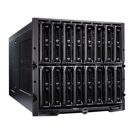
(see Figure 1-1, Figure 1-2, and Figure 1-3). To function as a system, a blade is inserted into a Dell PowerEdge M1000e enclosure (chassis) that supports power supplies, fan modules, a Chassis Management Controller (CMC) module, and at least one I/O module for external network connectivity. - Page 8 Figure 1-1. Blade Numbering—Half-Height Blades About Your System...
- Page 9 Figure 1-2. Blade Numbering—Full Height Blades Figure 1-3. Blade Numbering—Mixed Full-Height and Half-Height Blades About Your System...
- Page 10 Figure 1-4 shows the control panel features on the M1000e enclosure panel. Figure 1-4. Control Panel Features USB port (mouse only) video connector system power indicator NOTE: The USB and video ports are functional only if an optional iKVM module is installed.
-
Page 11: Lcd Module
LCD Module The LCD module provides an initial configuration/deployment wizard, as well as access to infrastructure and blade information, and error reporting. See Figure 1-5. Figure 1-5. LCD Module LCD screen selection ("check") button scroll buttons (4) About Your System... -
Page 12: Lcd Module Menus
LCD Module Menus Table 1-1. LCD Module Screen Navigation Keys Keys Left and right arrows Up arrow or down arrow Center button Main Menu The Main Menu options include links to the LCD Setup Menu, Server Menu, and Enclosure Menu. LCD Setup Menu You can change the default language and start-up screen for the LCD menu screens using this menu. - Page 13 Enclosure Menu The Enclosure Menu includes options for Module Status, Enclosure Status, and Network Summary. In the Module Status dialog box, you can highlight each component in the • enclosure and view its status. – A module that is powered off or booting is designated by a gray rectangle.
-
Page 14: Back-Panel Features
Back-Panel Features The back panel of the M1000e enclosure supports six I/O modules, one or two CMC modules, an optional iKVM module, nine fan modules, and six power supply modules. Figure 1-6 shows a fully configured enclosure. Figure 1-6. Back Panel Features fan modules (9) I/O modules (6) secondary CMC module... -
Page 15: Blades
Blades Figure 1-7. Front Panel Features—PowerEdge M910 blade-handle release button blade status/identification indicator blade power button hard drives (2) USB connectors (3) blade power indicator About Your System... - Page 16 Figure 1-8. Front Panel Features—PowerEdge M905 and M805 blade handle release button blade status/identification indicator blade power button About Your System hard drives (2) USB connectors (3) blade power indicator...
- Page 17 Figure 1-9. Front Panel Features—PowerEdge M710HD blade power indicator hard drives (2) USB connectors (2) blade handle release button blade status/identification indicator blade power button About Your System...
- Page 18 Figure 1-10. Front Panel Features—PowerEdge M710 blade handle release button USB connectors (3) blade power button About Your System hard drives (4) blade status/identification indicator blade power indicator...
- Page 19 Figure 1-11. Front Panel Features—PowerEdge M610x blade handle release button expansion-card filler-bracket retention latch with captive screw blade status/identification indicator blade power button hard drives (2) expansion-card slots (2) USB connectors (2) blade power indicator About Your System...
- Page 20 Figure 1-12. Front Panel Features—PowerEdge M610 blade handle release button blade status/identification indicator blade power button About Your System hard drives (2) USB connectors (2) blade power indicator...
- Page 21 Figure 1-13. Front Panel Features—PowerEdge M600 and M605 blade handle release button blade status/identification indicator blade power button hard drives (2) USB connectors (2) blade power indicator About Your System...
-
Page 22: Cmc Module
CMC Module Figure 1-14. CMC Module Features Ethernet connector Gb1 link indicator (2) DB-9 serial connector for local configuration primary CMC (CMC 1) status/identification indicator The CMC provides multiple systems management functions for your modular server, including the M1000e enclosure’s network and security settings, I/O module and iDRAC network settings, and power redundancy and power ceiling settings. -
Page 23: Cmc Daisy Chaining (Enclosure Stacking)
CMC Daisy Chaining (Enclosure Stacking) CMC daisy chaining can be utilized to minimize the number of network connections required for chassis (enclosure) management, such that only one or two network connections (depending on whether or not redundant CMCs are installed) are needed for up to four M1000e enclosures. Cabling Guidelines Follow these guidelines to daisy chain CMC modules from enclosure to enclosure:... - Page 24 Figure 1-15. CMC Daisy Chaining—Enclosure With Redundant CMC Modules management network segment CMC2—cable from connector Gb1 to network About Your System CMC1—cable from connector Gb1 to network...
-
Page 25: Ikvm Switch Module
NOTE: The iKVM USB ports do not support storage devices. – RJ-45 ACI port for tiering with Dell and Avocent analog KVM and KVM over IP switches with ARI ports. NOTE: Although the ACI port is an RJ-45 connector and uses Cat5 (or better) cabling, it is not an Ethernet network interface port. - Page 26 Figure 1-16 shows the external features of the iKVM module. Figure 1-16. Avocent iKVM Switch Module identification indicator ACI port for tiering connection only video connector CAUTION: Do not connect the ACI port to a LAN device such as a network hub. Doing so may damage the equipment.
-
Page 27: Initial System Configuration
Initial Setup Sequence 1 Unpack the enclosure and install it in a rack. For more information, see the Getting Started Guide and Rack Installation Guide at support.dell.com/manuals. CAUTION: Do not turn on the blades (server modules) until you have configured the switch modules, as described in "Configuring the I/O Modules"... -
Page 28: Configuring The Cmc
5 Configure the CMC network settings. The LCD Configuration Wizard allows you to quickly configure the CMC and iDRAC management interfaces and manage the enclosure remotely. See "Configuring the CMC Network Settings Using the LCD Configuration Wizard" on page 28. You can also use a management station and the RACADM CLI to configure the CMC. - Page 29 NOTE: The option to configure the enclosure using the LCD Configuration Wizard is only available until the CMC default password is changed or when the LCD Configuration Wizard is complete. Thereafter, use the RACADM CLI or the web- based GUI to change the CMC settings (see "Configuring the CMC Network Settings Using a Management Station and CLI"...
- Page 30 5 Review the settings on the Network Summary screen. – If the settings are correct, press the center button to close the configuration wizard and return to the Main Menu. – If the settings are not correct, use the left arrow key to return to the screen for that setting and correct it.
-
Page 31: Logging In To The Cmc Using The Web-Based Interface
3 Configure the CMC network settings: – To set a static IP address, type setniccfg -sand press . Use the appropriate settings for your network. To configure the CMC to obtain an IP address using DHCP , type –... -
Page 32: Adding And Managing Cmc Users
NOTE: The default CMC user name is root account is the default administrative account that ships with the CMC. For added security, you should change the default password of the root account during initial setup. NOTE: The CMC does not support extended ASCII characters, such as ß, å, é, ü, or other characters used primarily in non-English languages. -
Page 33: Configuring Idrac Networking Using The Web-Based Interface
1 Log in to the Web-based interface. See "Logging in to the CMC Using the Web-Based Interface" on page 31. 2 Select Chassis in the system tree. 3 Click the Network/Security tab, and then click the Users sub-tab. The Users page appears, listing each user’s user ID, login state, user name, and CMC privilege, including those of the root user. -
Page 34: Setting The First Boot Device For Servers
2 Click the plus (+) symbol next to Chassis in the left column, then click Servers. 3 Click Setup Deploy. 4 Select the protocol for the iDRAC setting (IPv4 and/or IPv6). 5 Enable the LAN for the iDRAC on the server by selecting the check box next to the server beneath the Enable Lan heading. -
Page 35: Configuring And Managing Power
Configuring and Managing Power You can use the Web-based and RACADM interfaces to manage and configure power controls on the CMC, as outlined in the following sections. For detailed information on the various power management options, see "Power Management" in the CMC User’s Guide. Configuring Power Budget and Redundancy The CMC’s power management service optimizes power consumption for the entire chassis (the chassis, servers, I/O modules, iKVM, CMC, and PSUs) and... - Page 36 CMC in the left slot as primary. Downloading the CMC Firmware Before beginning the firmware update, download the latest firmware version from support.dell.com, and save it to your local system. The following software components are included with your CMC firmware package: •...
-
Page 37
2 Type: racadm fwupdate -g -u -a
-d -m -
Page 38: Configuring The Optional Ikvm Switch Module
Configuring the Optional iKVM Switch Module Enabling iKVM Access to the Dell CMC Console Enabling access to the CMC allows you to access the CMC directly and securely through the iKVM’s CMC Console option. To enable the CMC Console using the Web-based interface: 1 Log in to the CMC Web-based interface. -
Page 39: Tiering The Avocent Ikvm Switch From An Analog Kvm Switch
Tiering the Avocent iKVM Switch From an Analog KVM Switch The Avocent iKVM switch can be tiered from analog KVM switches such as the Dell 2160AS and 180AS, as well as many Avocent analog KVM switches. Many switches may be tiered without the need for a Server Interface Pod (SIP) (see Table 2-1). -
Page 40: Tiering The Avocent Ikvm Switch From A Digital Kvm Switch
The iKVM module may also be tiered from a digital KVM switch such as the Dell 2161DS-2 or 4161DS, or a supported Avocent digital KVM switch. Many switches may be tiered without the need for a SIP (see Table 2-2). -
Page 41: Viewing And Selecting Servers
(version 3.6 or later) Avocent DSR 800, x16x, x010, 1024 To tier the iKVM module from a Dell 2161DS, 180AS, or 2160AS console switch: • If the switch does not require a SIP to connect to the iKVM (see Table 2-2), connect a Cat5 (or newer) cable to the RJ-45 ACI port on the iKVM module. -
Page 42
To access the dialog box: Main Press
to launch the OSCAR interface. The displayed. If a password has been assigned, the Password dialog box is displayed. Type your password and click OK. The Resynchronizing the Server List at the Remote Client Workstation Once the iKVM module is connected, the blades appear in OSCAR. -
Page 43: Flexaddress
6 Select the type of switch connected to the appliance from the drop-down list. If the type you are looking for is not available, you can add it by clicking Add. 7 Click Next. The completion dialog box is displayed. 8 Click Finish to exit. -
Page 44: Activating Flexaddress
For example:(starting_mac)00188BFFDCFA + 0xCF = (ending_mac)00188BFFDDC9 NOTE: You must lock the SD card prior to inserting in the USB "Memory Card Reader" to prevent accidently modifying any of the contents. You must unlock the SD card before inserting into the CMC. FlexAddress Plus The FlexAddress Plus is a new feature added to the feature card version 2.0. - Page 45 For more information on the FlexAddress feature, see the following resources: • The CMC Secure Digital (SD) Card Technical Specification document at support.dell.com. • The Help link in the CMC Web interface. The "Using FlexAddress" chapter in the CMC User’s Guide.
- Page 46 Initial System Configuration...
-
Page 47: Configuring The I/O Modules
Configuring the I/O Modules Overview The M1000e enclosure supports three layers of I/O fabric. Each layer may contain Ethernet, Infiniband, and Fibre Channel modules. Additional fabrics may be supported in the future. You can install up to six hot-swappable I/O modules in the enclosure, including Fibre Channel switches, Fibre-Channel pass-throughs, Infiniband switches, Ethernet switches, and Ethernet pass- through modules. - Page 48 Fabric A Fabric A is a redundant Gb Ethernet fabric, supporting I/O module slots A1 and A2. The integrated Ethernet controllers in each blade dictate Fabric A as an Ethernet-only fabric. NOTE: Fabric A supports KR (10 Gbps standard) if the midplane version in the enclosure is 1.1 or later.
-
Page 49: Identifying Midplane Version
For more information about I/O module installation guidelines, see your Hardware Owner’s Manual. Identifying Midplane Version The version of the midplane installed in the enclosure is displayed in the Midplane Revision field under the Summary tab of the CMC web-based interface. - Page 50 Figure 3-2. Identifying Midplane Version 1.1 midplane identification labels (2) Configuring the I/O Modules...
- Page 51 Figure 3-3. Identifying Midplane Version 1.0 midplane identification labels (2) Configuring the I/O Modules...
-
Page 52: Before You Begin
Before You Begin Network Information You can configure your I/O switch modules using: • The CMC (see "Configuring a Switch Module Network Ethernet Port Using the Web-Based Interface" on page 52). NOTE: The default IP address for the CMC is 192.168.0.120. •... -
Page 53: Dell Powerconnect-Kr 8024-K Switch
After all I/O modules have been configured and connected, the enclosure’s blades can be inserted and booted with full network communication. Dell PowerConnect-KR 8024-k Switch The PowerConnect M8024-k switch provides 16 internal 10 GbE ports, four external 10 GbE SFP+ ports, and one 10 GbE expansion slot for 10 GbE external uplinks. - Page 54 Figure 3-4. Dell PowerConnect-KR 8024-k Switch SFP+ ports (4) status/identification indicator expansion slot Configuring the I/O Modules console management connector power indicator...
-
Page 55: Dell M8428-K 10 Gb Converged Network Switch
Dell M8428-k 10 Gb Converged Network Switch The Dell M8428-k 10 Gb Converged Network switch module supports FCoE protocols and allows Fibre Channel traffic to travel over 10 Gbps Enhanced Ethernet (DCB) networks. This module consists of: • Four 8 Gbps external autosensing Fibre Channel ports. - Page 56 Figure 3-5. Dell M8428-k 10 Gb Converged Network Switch LED status indicators (12) module status indicator power indicator 10 GbEE ports (ports 17–24) Configuring the I/O Modules serial port (RJ-45 connector) status indicator 8 Gb Fibre Channel ports (ports 25–27 and port 0)
-
Page 57: Mellanox M2401G Ddr Infiniband Switch I/O Module
Mellanox M2401G DDR Infiniband Switch I/O Module The Mellanox M2401G Infiniband switch I/O module includes 24 4x DDR Infiniband ports. Eight ports are external uplink ports, while 16 internal ports provide connectivity to the blades in the enclosure. Figure 3-6. Mellanox M2401G Infiniband Switch Module Infiniband ports (8) port activity indicators (8) module status indicator... -
Page 58: Mellanox M3601Q Qdr Infiniband Switch I/O Module
Mellanox M3601Q QDR Infiniband Switch I/O Module The Mellanox M3601 Infiniband switch I/O module includes 32 4x QDR Infiniband ports. Of these, 16 ports are external uplink ports, while 16 internal ports provide connectivity to the blades in the enclosure. This module occupies two I/O module slots. - Page 59 Figure 3-7. Mellanox M3601Q Infiniband Switch Module Infiniband ports (16) port activity indicators (16) module status indicator port link status indicators (16) module diagnostic power indicator Configuring the I/O Modules...
-
Page 60: Cisco Sfs M7000E Infiniband Switch I/O Module
Cisco SFS M7000e Infiniband Switch I/O Module The Cisco SFS M7000e Infiniband switch module includes 24 4x DDR Infiniband ports. Eight ports are external uplink ports, and 16 internal ports provide connectivity to the blades in the enclosure. This switch module is hot-swappable, and may be installed in Fabric B or Fabric C. -
Page 61: Cisco Catalyst Ethernet Switch I/O Modules
Cisco Catalyst Ethernet Switch I/O Modules Your system supports three Cisco Catalyst Blade Switch (CBS) versions: • The Cisco 3130G-S switch includes four 10/100/1000 Mb Ethernet uplink ports and two Stackwise Plus ports. • The Cisco CBS 3130X-S switch includes four 10/100/1000 Mb Ethernet uplink ports, two 10 Gb uplink ports, and two Stackwise Plus ports. - Page 62 Figure 3-9. Cisco Catalyst Ethernet Switch Module Features Stackwise Plus connectors (not enabled in CBS 3032) option bays (2) mode button power indicator Configuring the I/O Modules 10/100/1000 Mb Ethernet connectors (4) Cisco status indicators console port for switch management status/identification indicator...
-
Page 63: Powerconnect M6220 Ethernet Switch I/O Module
PowerConnect M6220 Ethernet Switch I/O Module The PowerConnect M6220 Ethernet switch module includes four external 10/100/1000 Mbps Ethernet connectors and one USB type A form factor serial connector. Two option bays support the following modules: • A resilient stacking module with 2 x 24 Gb stacking ports •... - Page 64 Figure 3-10. PowerConnect M6220 Ethernet Switch Module Features optional module (2) (dual 10 Gb Ethernet uplink module shown) serial connector (USB type-A form factor) status/identification indicator Configuring the I/O Modules standard 10/100/1000 Mb Ethernet connectors (4) power indicator...
-
Page 65: Powerconnect M6348 1 Gb Ethernet Switch I/O Module
PowerConnect M6348 1 Gb Ethernet Switch I/O Module The PowerConnect M6348 is a hot-swappable 48-port 1 Gb Ethernet switch. While 16 ports are external uplink ports, the remaining 32 internal ports provide connectivity to the blades within the enclosure with a maximum bandwidth of 1 Gbps each. - Page 66 Figure 3-11. PowerConnect M6348 Switch Module standard 10/100/1000 Mb Ethernet connectors (16) CX4 stacking connectors (2) power indicator Configuring the I/O Modules SFP+ connectors (2) console management connector status/identification indicator...
-
Page 67: Powerconnect M8024 10 Gb Ethernet Switch I/O Module
PowerConnect M8024 10 Gb Ethernet Switch I/O Module The PowerConnect M8024 switch module incorporates two optional bays that support the following modules: • A 10 Gb Ethernet module with four optical SFP+ connectors • A 10 Gb Ethernet module with three copper CX4 uplinks •... - Page 68 Figure 3-12. PowerConnect M8024 Switch Module optional module with four SFP+ ports serial connector for optional USB type-A form-factor cable status/identification indicator Configuring the I/O Modules optional module with three CX4 ports power indicator...
-
Page 69: Brocade M4424 San I/O Module
Brocade M4424 SAN I/O Module The Brocade M4424 SAN I/O module includes eight external autosensing Fibre Channel ports (four ports are enabled in the standard configuration and four additional ports may be enabled as an optional upgrade), 16 internal ports, and one serial port with an RJ-45 connector. The external Fibre Channel ports operate at 1 Gb/sec, 2 Gb/sec, or 4 Gb/sec. - Page 70 Figure 3-13. Brocade M4424 SAN I/O Module Fibre Channel port (8) Fibre Channel port speed indicator (8) module status indicator status/identification indicator Configuring the I/O Modules Fibre Channel port status indicator (8) serial port (RJ-45 connector) power indicator...
-
Page 71: Brocade M5424 Fc8 I/O Module
Brocade M5424 FC8 I/O Module The Brocade M5424 I/O module includes eight external autosensing Fibre Channel ports (four ports are enabled in the standard configuration and four additional ports may be enabled as an optional upgrade), 16 internal ports, and one serial port with an RJ-45 connector. The external Fibre Channel ports operate at 8 Gb/sec, 4 Gb/sec, or 2 Gb/sec. - Page 72 Figure 3-14. Brocade M5424 FC8 I/O Module Fibre Channel port (8) Fibre Channel port speed indicator (8) module status indicator status/identification indicator Configuring the I/O Modules Fibre Channel port status indicator (8) serial port (RJ-45 connector) power indicator...
-
Page 73: Dell 8/4 Gbps Fc San Module
Dell 8/4 Gbps FC SAN Module The Dell 8/4 Gbps FC SAN module (see Figure 3-15) includes 24 total autosensing Fibre Channel ports (12 ports are enabled in the standard configuration and 12 additional ports may be enabled as an optional upgrade) and one serial port with an RJ-45 connector. - Page 74 Figure 3-15. Dell 8/4 Gbps FC SAN Module Fibre Channel port (8) Fibre Channel port speed indicator (8) module status indicator status/identification indicator Configuring the I/O Modules Fibre Channel port status indicator (8) serial port (RJ-45 connector) power indicator...
-
Page 75: Pass-Through Modules
Pass-Through Modules Dell 10 GbE KR Pass-Through I/O Module The 10 GbE KR pass-through module supports 10 Gb connections and provides a direct connection between the optional internal Ethernet KR mezzanine card or KR network daughter card in the blade and an external Ethernet device. - Page 76 Figure 3-16. Dell 10 GbE KR Pass-Through I/O Module SFP+ ports (16) status/identification indicator Configuring the I/O Modules green/amber indicators (two per port) power indicator...
-
Page 77: Dell 8/4 Gbps Fibre Channel Pass-Through I/O Module
Dell 8/4 Gbps Fibre Channel Pass-Through I/O Module The 8G Fibre Channel pass-through module provides a bypass connection between a Fibre Channel mezzanine card in the blade and optical transceivers. The bypass connection enables a direct connection to a Fibre Channel switch or a storage array. - Page 78 Figure 3-17. Dell 8/4 Gbps Fibre Channel Pass-Through I/O Module Fibre Channel ports (16) status/identification indicator Configuring the I/O Modules port status indicators power indicator...
-
Page 79: Gb Ethernet Pass-Through Module
10 Gb Ethernet Pass-Through Module II The Dell 10 Gb Ethernet pass-through module II supports 10 Gb connections and provides a direct connection between the optional internal Ethernet mezzanine card in the blade and an external Ethernet device. The Ethernet pass-through modules are hot-swappable and may be installed in Fabric B or Fabric C. - Page 80 Figure 3-18. 10 Gb Ethernet Pass-Through Module II SFP+ cages (16) status/identification indicator Configuring the I/O Modules green/amber indicators (two per port) power indicator...
-
Page 81: 10 Gb Ethernet Pass-Through I/O Module
10 Gb Ethernet Pass-Through I/O Module The 10 Gb Ethernet pass-through module supports 10 Gb connections and provides a direct connection between the optional internal Ethernet mezzanine card in the blade and an external Ethernet device. The Ethernet pass-through modules are hot-swappable and may be installed in Fabric B or Fabric C. - Page 82 Figure 3-19. 10 Gb Ethernet Pass-Through I/O Module SFP+ cages (16) power indicator Configuring the I/O Modules green/amber indicators (two per port) status/identification indicator...
-
Page 83: 10/100/1000 Mb Ethernet Pass-Through I/O Module
10/100/1000 Mb Ethernet Pass-Through I/O Module The Ethernet pass-through module supports 10/100/1000 Mb connections and provides a direct connection between the optional internal Ethernet mezzanine card in the blade and an external Ethernet device. The Ethernet pass-through modules are hot-swappable and may be installed in any of the three Fabrics. - Page 84 Figure 3-20. Ethernet Pass-Through Module link indicator (16) power indicator activity indicator (16) NOTE: Connectors on the Ethernet pass-through module correspond directly to the blade number. For example, blade 5 is connected to port 5 on the Ethernet pass- through module. Integrated network adapter 1 maps to I/O slot A1. Integrated network adapter 2 maps to I/O slot A2.
-
Page 85: 4G Fibre Channel Pass-Through I/O Module
4G Fibre Channel Pass-Through I/O Module The 4G Fibre Channel pass-through module provides a bypass connection between a Fibre Channel mezzanine card in the blade and optical transceivers. The bypass connection enables a direct connection to a Fibre Channel switch or a storage array. - Page 86 Figure 3-21. 4G Fibre Channel Pass-Through Module SFP Fibre Channel connector (16) power indicator Configuring the I/O Modules Fibre Channel green/amber indicators (two per port) status/identification indicator...