D-Link DVG-2032S User Manual
D-link voip gateway user manual
Hide thumbs
Also See for DVG-2032S:
- User manual (75 pages) ,
- Quick installation manual (23 pages) ,
- Quick installation manual (7 pages)

Related Manuals for D-Link DVG-2032S


Summary of Contents for D-Link DVG-2032S
-
Page 1: User Manual
DVG-2032S VOIP Gateway User Manual Version 1.0... -
Page 3: Table Of Contents
Gateway Assigned with a Public IP Address... 4 Gateway in a NAT network ... 5 Telephone Interface Description... 6 Example for DVG-2032S:... 6 3. Setting the Gateway through IVR...7 IVR (Interactive Voice Response) ... 7 IVR Functions Table: ... 9 IP Configuration Settings—Setting IP Configuration of WAN Port... - Page 4 3. Coding Principle ...46 Instruction... 46 Dialed Number Processing Flow... 46...
-
Page 5: Introduction
1. Introduction Product Overview The stand-alone VoIP Gateway carries both voice and facsimile over the IP network. It supports SIP industry standard call control protocol to be compatible with free registration services or VoIP service providers’ systems. It works in two different modes: UA (User Agent) or Server. As a standard user agent, it is compatible to all well-known Soft Switches and SIP proxy servers. -
Page 6: Product Features
Product Features ● SIP (RFC 3261) compliant ● Optional server enables small businesses to build up private VoIP network (SIP model) ● QoS support guarantees voice bandwidth in a busy network ● Supports IP TOS (Type Of Service) ● T.30 (G III) / Real Time T.38 / Secured T.38 Fax Relay ●... -
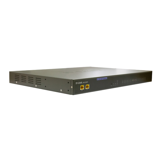
Page 7: Hardware Description
Rear Panel NOTE: Do not connect Phone ports to each other. Also, do not connect any Phone ports directly to a PSTN line or internal PBX. If any of these are done, your DVG-2032S may be damaged. Restore to factory default: (IP address, User’s. Name and Password) (1) Pull off the power plug. -
Page 8: Installation And Applications
2. Installation and Applications Network Interface The network interface is divided into 3 basic modes as described below: Gateway can be assigned with a Public IP Address Gateway can be built under the existing NAT Gateway Assigned with a Public IP Address The gateway will have a Public IP address for Internet connection regardless of whether it is a static IP address, DHCP (using a Cable Modem), or PPPoE (Dialup / ADSL). -
Page 9: Gateway In A Nat Network
Gateway in a NAT network The gateway uses a virtual IP address and the IP sharing function of other systems to connect to the Internet. LAN IP address of IP sharing Gateway IP Settings NAT /STUN Settings DDNS Settings Please avoid IP address 192.168.0.1-192.168.8.254 (You may need to change the settings of IP sharing or change SIP series Gateway LAN Port IP address) Set as static IP address, and assign the LAN IP address of the IP... -
Page 10: Telephone Interface Description
Telephone Interface Description Example for DVG-2032S: DVG-2032S connecting directly to phone sets After connecting telephone sets to P1-P32, users can make direct calls, (P1-P32 are FXS interfaces). Each set acts as an independent extension line. Integrating the DVG-2032S with PBX P1-P32 is FXS interfaces, and some of them can be connected to telephone sets for direct calls. -
Page 11: Setting The Gateway Through Ivr
3. Setting the Gateway through IVR VoIP transmits voice data (packet) via the Internet to achieve telecommunications. This means that the telecommunication quality is closely related to the whole network environment. If any one of the telecommunicating parties has insufficient bandwidth or frequent packet loss, the telecommunication quality will be poor. - Page 12 Instructions FXS Port: Connected to telephones. To enter IVR mode, enter “ * * password #” after hearing enter the function code. (Please refer to the Advanced Settings on page 35 for these codes) Example: The factory default code is blank. Enter “**#”. You are now in IVR setting mode, enter the desired code.
-
Page 13: Ivr Functions Table
IVR Functions Table: Function Code Description 111/101 WAN Port IP address Set/Query 112/102 WAN Port Subnet Mask Set/Query 113/103 WAN Port Default Gateway Set/Query 114/104 Current Network IP Access Set/Query (1: Static IP, 2.DHCP, 3.PPPoE) 115/105 DNS IP address Set/Query 116/106 Phone books manager IP address Set/Query 117/107... - Page 14 Function Code Description 215/205 Set/Query Gateway Telephone Number (Representative Number) 216/206 Set/Query the extension number of Line 1. 217/207 Restoring factory default IP address configuration Restoring factory default settings Save settings Setting IVR and the language used on the Web GUI (1: English, 2: Traditional Chinese, 3: Simplified Chinese) Soft Upgrade...
-
Page 15: Ip Configuration Settings-Setting Ip Configuration Of Wan Port
IP Configuration Settings—Setting IP Configuration of WAN Port Static IP Settings NOTE: Complete static IP settings should include a static IP (Option 1 under114), IP address (111), Subnet Mask (112), and Default Gateway (113). Please contact your local Internet Service Provider (ISP) if you have any questions. Function Command Select a Static IP... - Page 16 PPPoE Account Settings After entering IVR mode, dial 121. After hearing “Enter value”, enter the account number, followed by ”#”. Example: If the account is “84943122 @ hinet.net”, please enter 08 04 09 04 03 01 02 02 71 48 49 54 45 60 72 54 45 60 #.
- Page 17 PPPoE Character Conversion Table Number Input Key Upper Case Letter Input Key Lower Case Input Key Letter Symbol Input Key • " & < >...
-
Page 18: Setting A Gateway With Web Browser
1. Setting a Gateway with WEB Browser The gateway allows users to make settings using a web browser. After opening a browser, enter Gateway’s IP address as the website address in order to enter the Web configuration screen as shown in the following diagram. - Page 19 Listen Port UDP: It is not necessary to change the protocol of the communication port used by the gateway. RTP Starting Port UDP: The initial value of port number for transmitting voice data among Gateway(s). Each line requires 2 ports (RTP/RTCP). It is not necessary to change these. For example: If the starting port is 9000, then Line 1 is using 9000(RTP) and 9001(RTCP),...
- Page 20 and Line 2 is using 9002 and 9003, and so forth. IP Configuration (Setting WAN Port) There are four methods of obtaining a WAN port IP address: 1. Static IP 2. DHCP, means a Dynamic IP (Cable Modem) 3. PPPoE (Dialup ADSL) 4.
- Page 21 Select “PPTP” and enter the IP Address, Subnet mask, PPTP Server, PPTP ID and Password. Then click the “Accept” button at the bottom. BigPond (for Australia use only) Click “BigPond Cable” Enter User Name and Password. Login Server is optional. Then click the “Accept” button at the bottom.
- Page 22 Some Internet Service Providers (ISP) assigns the bandwidth via the MAC (Media Access Control) Address. You can click the " Clone" button to copy the MAC address of the Ethernet Card installed in the computer used to configure the device. It is only necessary to fill in the field if required by your ISP. The “Your MAC Address”...
-
Page 23: Network Settings (Lan)
Network Settings (LAN) LAN interface mode※ Router: The system serves as a router with NAT. Bridge: The system serves as a bridge between WAN port and LAN port without NAT. (LAN default gateway will still be accessible for configuration). LAN IP/Subnet mask Gateway LAN Port IP address and the subnet mask value. -
Page 24: Qos Settings
QoS Settings WAN QoS QoS (Quality of Service): Sets an external bandwidth to ensure sound quality during transmission (When this function is enabled, the voice packet has the highest priority to ensure telecommunication quality while less bandwidth is assigned for data transmission). Some models of the gateway without this function can adjust the bandwidth automatically. -
Page 25: Nat/Ddns
NAT/DDNS NAT Traversal If a Gateway is set up under an IP sharing setting, you can select either the NAT or STUN protocol. NAT Public IP: The IP address used by the gateway should be a virtual address. Further more, users must set the Virtual Server Mapping in the NAT Server (A virtual server is defined as a Service Port, and all requests to this port will be redirected to this specified the server IP address). - Page 26 DDNS These settings are only necessary when the gateway is set up under a NAT that uses a dynamic IP address and do not support DDNS.
-
Page 27: Telephony Settings
Choose a DDNS Server: The current system allows users to choose either DynDNS、TZO、3322.org、 PeanutHull or a private server. Please apply for a user account before choosing a service provider. Server address: Sets up the IP address or URL (Uniform Resource Locator) of the DDNS Server. - Page 28 Enable: Enable a line; if some lines are not used, disable them (Pause Function) to avoid unnecessary waiting when an incoming call is diverting to this line. Hotline Functions FXS port: When the user picks up the phone, the gateway automatically dials your assigned hotline number.
-
Page 29: Sip
Hunting/Ring: It is able to set FXS group hunting using simultaneous ring or sequential ring. Sequential Ring Time: To set the ring time of each port, when sequential ring is chosen. All Call through OutBound Proxy:An outbound proxy server handles SIP call signaling as a standard SIP proxy server would. - Page 30 SIP Message Resend Timer Base: SIP packet will resend if response didn't arrive in the base time set in this column. It will send again at "base time" * 2, and send again at "base time" *2 *2. The max of resend time is 4 sec. Resend will stop/restart when total resend 20sec has reached.
- Page 31 Enable Support of SIP Proxy Server / Soft Switch: Enable the functions to inter-work with Proxy Server / Soft Switch. When SIP Proxy 1 and 2 are enabled, the system will register to SIP Proxy 2 after all lines are failed to register to SIP Proxy 1. SIP Proxy 2 is a backup system.
- Page 32 FXS Representative Number: Register all FXS ports as a hunting group. Register: Register to Proxy if ticked. Invite with ID / Account: DVG-2032S can be invited to a VoIP trunk gateway w/o register to a Proxy. Please contact your ITSP NOTE: Please ensure that if Proxy Server allows one account for many ports using before using representative number to register.
-
Page 33: Calling Features
Calling Features Do Not Disturb: It will only be able to call out when it is enabled. Unconditional Forward: All incoming calls will be forwarded to the “Forwarding Number” automatically. If it forwards to FXO, it only make FXO hook off, not make FXO dial out. Busy Forward: Forward the incoming call to “Forwarding Number”... - Page 34 Calling Feature Instructions: Call Hold: Ongoing call will be put on hold after FLASH button pressed on the phone set. The gateway will play a repeating music to the remote end. Call Transfer: Ongoing call will be put on hold after FLASH button pressed on local phone set (gateway plays a repeating music to the remote end).
-
Page 35: Advanced Options
Advanced Options There are two levels to enter Web. Administrator is able to change all settings. Web UI only changes some settings. NOTE: Enter new Login ID and password for two levels. Web UI auto log out: When logging in a web page, if a user does not act within the effective time range, the user will be disconnected from the web page to allow others to login. -
Page 36: Line Settings
Enable Out-of-Band DTMF: To send DTMF keys (0~9, *, #,) follow the RFC2833 rules or via SIP Info. Enable Hook Flash Event: The gateway will deliver the flash signal to remote party via RFC2833 or SIP Info. Payload Type:Payload type of RFC2833. Uses Second CPT for VoIP Call: This function is usually applied when the user selects VoIP as the primary path for outgoing calls and PSTN as the backup. -
Page 37: Fax Settings
the sound quality and occupied bandwidths are also different. It is recommended to use the default provided (G.723.1) because it occupies less bandwidth and will provide better sound quality. Jitter Buffer: Adjusts the jitter to receive a packet. If the jitter range is too wide, it will delay voice transmission. - Page 38 Drop Silent Call Timeout: Set the time to hang up the phone.
-
Page 39: Digit Map
Digit Map There are 50 sets of leading digit entries to choose voice routing interface – Auto select, PSTN or VoIP. Default Call Route: The default call route can be Auto, VoIP and Deny. Auto (VoIP first): The call route is VoIP first, and the next is Deny. VoIP: The call route is VoIP only. -
Page 40: Caller Filter
Method 1- Single mapping: Fill a short code into the “Speed Dial Code” column, and enter the desired phone number into the “Number To Dial” column. For example, pick up the handset and dial 55# and the system will dial 32568791. Method 2- Multi mapping;... -
Page 41: Cdr Settings
CDR Settings The user can set up a CDR Server to record call details for every phone call. The present CDR provides the call detail recording in a text file and if needed. it can be imported to prepare for an analysis report. Send record to CDR Server: Enables the call detail recording function. -
Page 42: System Information
System Information This page shows that the status of VoIP Gateway. There are Port Status, Server Registration Status, WAN Port Information, LAN Port Information and Hardware. Port Status: It includes if each port registers to Proxy successfully, the lasted dialed number, how many calls each port had since the system is start, etc. -
Page 43: Rtp Packet Summary
RTP Packet Summary Displays the information of the last finished call. It contains peer IP, peer port, packets sent, packet received and packet lost. Press the button of Refresh to get the latest RTP Packet Summary. STUN Inquiry Use STUN Inquiry to know what NAT type of the router. Ping Test Use “ping”... -
Page 44: Snmp
SNMP Enable SNMP Agent: Enable SNMP if ticked. Get/Set/Trap Community: Enter Community name to Read, Write and Trap. Trap Host: Enter the IP of Trap Host. This is the time setting. After the gateway is on the Internet, it will set its watch with Time Server. Time Zone: Set the Time Zone where the gateway resides. -
Page 45: Provision Settings
Provision Settings Fill in the parameters needed of Provision Server from your provider. System Operations (Save Settings) Some settings are effective by Restart. Remember to save all settings by Save Settings before to restart. Save Settings: Save settings after completing. The new settings will take effect after the system is restarted. -
Page 46: Software Upgrade
Software Upgrade Gateway provides software upgrade function for a remote end. Your provider gives all parameters. Upgrade Server: Choose the server type of your provider. Software Upgrade Server IP: Enter the software server IP address. Software Upgrade Server Port: Enter the port that server uses. TFTP is 69, and FTP is 21. -
Page 47: Ip Sharing Functions
2. IP Sharing Functions All Gateway series have a built-in IP sharing function. The settings and instructions at a PC end are described below: Current Intranet only supports static IP mode, and the settings at the PC end are as follow: Available IP address Range : 192.168.8.1 –... - Page 48 The IP settings on PC are as follows (using Windows 2000 for example) Open Start->Settings->Control Panel Open Network and Dial-up Connection Open Local Area Connection Click Properties Select TCP/IP, and then click Properties.
- Page 49 Select “Use the following IP Address ” and enter IP address, Subnet Mask, and Default Gateway. Please note that an IP address in the same domain cannot be reused. Then, enter the DNS server IP address (varies in different networks. consult your ISP’s service for information). Click the “OK” button and after completing the settings, users can use both the VoIP and network services concurrently.
-
Page 50: Dialed Number Processing Flow
3. Coding Principle Instruction After a phone number is entered, dial # to call out immediately or, wait until the “Inter DTMF Timeout” expires (defined in “Advanced Options”, default=4 seconds). If the phone number fits the setting of Digit Map, the gateway dials out the phone number through the assigned interface automatically. - Page 51 Dial the number defined in SpeedDial table Dial (D#) through the first available FXO port to PSTN Start Enter a phone number (D#) Is (D#) defined in Speed Dial table? Is (D#) defined in Extension table? Is (D#) defined in Phonebook table? Is (D#) defined in Phonebook...