
Related Manuals for Airmar SMARTFLEX DFM-1000-SA-L

Summary of Contents for Airmar SMARTFLEX DFM-1000-SA-L
- Page 1 Diesel Flow Meter Installation and User Manual D-21349-rev.1 102945-rev.1 02/24/23...
-
Page 2: Theory Of Operation
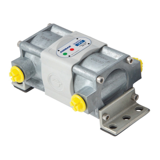
5. Use of engine rated particulate filters is recommended Theory of Operation The Airmar DFM operation is based on the measurement of fuel volume passing through the flow chamber. The fuel pressure passing through the chamber causes the ring slides along the inner wall to rotate, which generates a pulse used to measure volume. -
Page 3: Electrical Connection
The flow meter can be installed up to 30 degrees of incline (fuel output up) Electrical Connection The DFM comes equipped with a M12 Device Net connector to aid in a quick and easy connection. Sensor Connections should be made to the secondary bus of the ASM as dictated by the ASM Installation guide for Digital Sensors. -
Page 4: Fuel Line Connection
1.4 Fuel Line Connection Refer to the sensor specifications to determine inlet and outlet thread type and diameter. Sensor Connections should be made to the secondary bus of the ASM as dictated by the ASM Installation guide for Digital Sensors. Up to 10 Fuel Flow sensors can be connected to a single ASM s econdary bus input. - Page 5 LCD Operation (if applicable) Informational screens are switched/advanced when the surface below the display is tapped with a magnetic key (included with LCD sensor variant). In order to save the charge of the built-in battery, the display goes to sleep mode one minute after the last touch of the cover by the magnetic key.
- Page 6 Units Screen Digit Displayed data Metric System US System of capacity of Measures Measures “Total Fuel Consumption” 0.00001 m³ Counter 0.01 “Total Fuel Consumption” 0.000001 m³ Counter with higher digit 0.001 capacity “Engine Operation Time” Counter “Engine Operation Time” in “Idle”...
- Page 7 Screen 3 displays the Counter readings “Engine Operation Time” accumulated as the total time of engine operation in all modes including idle run. Screens 4…6 display the Counters readings of “Engine Operation Time in “Idle”, “Optimal” and in “Overload” Modes” accumulated by DFM as a total engine operation time in corresponding modes.
- Page 8 The unit displays vertical strokes in “Interference” Mode Display view in “Interference” Mode The meter will automatically exit Interference mode a few seconds after operation and revert to normal operation conditions. For full instructions for setting your DFM up in the SmartFlex Software, visit: https://www.airmar.com/uploads/InstallGuide/D-20189.pdf#page=87...