
Related Manuals for Panasonic AJ-LT95


Summary of Contents for Panasonic AJ-LT95
- Page 1 Printed in Japan VQT8648 Lap-Top Editor Operating Instructions Use the dedicated AJ-B95 AC adapter. F0500W @...
- Page 2 IMPORTANT “Unauthorized recording television programs, video tapes and other materials may infringe the right of copyright owners and be contrary to copyright laws.” CAUTION RISK OF ELECTRIC SHOCK DO NOT OPEN CAUTION: TO REDUCE THE RISK OF ELECTRIC SHOCK, DO NOT REMOVE COVER (OR BACK). NO USER SERVICEABLE PARTS INSIDE.
-
Page 3: Table Of Contents
Contents Features ......5 Opening and closing the top panel ..6 Parts and their functions . - Page 4 Contents Sending and loading edit (DUMP) (LOAD) data to an external component ..81 Superimposed screen ....85 Error messages ....86 Video head cleaning .
-
Page 5: Features
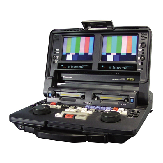
Features Compact size and light weight This editor is an integrated editing system which delivers two DVCPRO 50 digital VTRs, an editing controller, two LCD monitors and speakers in a single unit. It features a compact, lightweight and portable design which enables it to be easily carried around and readily utilized for editing work on an office desk, etc. -
Page 6: Opening And Closing The Top Panel
Opening and closing the top panel Opening the top panel Pull the top part of the lever forward to release the lock. Clasp both sides of the top panel, and lift the panel to open it.Do not try to lift the panel by pushing the lever up. Closing the top panel Push the top panel down to close it and engage the bottom part of the lever. -
Page 7: Parts And Their Functions
Parts and their functions BACKLIGHT LIGHT DARK BRIGHTNESS COUNTER/ REMAIN METER FULL/ FINE RESET EJECT < Panel control area 1 Audio monitor speakers The sound of the VTR1 (or VTR2) signals to be monitored is delivered through the VTR1 (or VTR2) speaker. - Page 8 Parts and their functions BACKLIGHT LIGHT DARK BRIGHTNESS COUNTER/ REMAIN METER FULL/ FINE RESET EJECT < VTR 1 Panel control area 5 METER button While this is held down, the audio level meter is set to the fine mode. (See page 10) 6 RESET button Used to reset the CTL counter.
-
Page 9: Counter Display Area
Parts and their functions INPUT SCH REF SCH EDIT REC Counter display area 1 “Cassette inside” display This lights when a cassette has been inserted. It flashes when the unit is in the STANDBY OFF mode. 2 INPUT SCH lamp INPUT lights when video signals have been supplied from an external source. - Page 10 Parts and their functions INPUT SCH REF SCH EDIT REC > Counter display area < TOTAL lamp This lights when the total editing time is displayed. = REMAIN lamp This lights when the remaining tape amount is displayed. > W lamp This lights in the wide-screen mode.
- Page 11 Parts and their functions Counter display area E Event number display lamps This unit controls up to 200 sets of edit data (001 to 200) in the form of 3-digit event numbers. One of the following displays appears depending on the editing status.
-
Page 12: Panel Switch Area
Parts and their functions CONTROL PREROLL SYNCHRO REMOTE TAPE LOCAL EXT VTR Panel switch area 1 CONTROL switch REMOTE: For controlling the unit from the REMOTE connector (9P). LOCAL: For controlling the unit using the controls on its front panel. EXT VTR: For controlling an external VTR using the controls on the unit’s front panel. - Page 13 Parts and their functions CONTROL PREROLL SYNCHRO MODE REMOTE TAPE LOCAL EXT VTR Panel switch area 7 ANALOG AUDIO IN switch Used to set the allocation of the audio signals to the 4 analog audio input connectors (on the rear panel). V1-V2 (2ch): Of the 4 inputs, the two on the VTR1 side are supplied to the VTR1’s input connectors, and the two on the VTR2...
-
Page 14: Audio Control Area
Parts and their functions POWER CH 1 CH 2 V1/V2 ANALOG AUDIO control area 1 POWER switch Used to control the unit’s power. 2 AUDIO MONITOR SELECT switches Used to select the audio monitor output and speaker output. O V1/V1•2/V2 switch The VTR1 sound is output to the left and right channels. - Page 15 Parts and their functions POWER CH 1 CH 2 V1/V2 ANALOG AUDIO control area 4 V1 audio playback level controls/V2 INT audio recording level controls These controls enable the playback audio level of VTR1 to be adjusted for each channel. They are also used to adjust the volume during editing from VTR1 to VTR2.
- Page 16 Parts and their functions POWER CH 1 CH 2 CH 3 V1/V2 ANALOG AUDIO control area 6 SDI audio recording level controls and UNI/VAR switch For each channel of the superimposed sound which is input from the SDI input connector (on the rear panel) there is one level control.
-
Page 17: Editing Operation Area
Parts and their functions POWER CH 1 CH 2 V1/V2 ANALOG Editing operation area 1 VTR1 selector button Press this button to perform VTR1 editing-related settings or operations. Check that its LED has lighted before proceeding with VTR1 editing-related operations. 2 VTR2 selector button Press this button to perform VTR2 editing-related settings or operations. - Page 18 Parts and their functions POWER CH 1 CH 2 V1/V2 ANALOG Editing operation area 8 Search dial This is used to control the tape travel. It is also used when edit points are to be located or when playing back tapes. The shuttle mode is established when the dial is “out”...
- Page 19 Parts and their functions POWER CH 1 CH 2 CH 3 V1/V2 ANALOG Editing operation area < A2 (A4) button A2: Press this button to initiate audio channel 2 insert editing. Check that its LED has lighted before proceeding with editing. A4 ([SHIFT] + [A2]): To initiate audio channel 4 insert editing, press the A2 button while holding down the SHIFT...
- Page 20 Parts and their functions ? @ A B POWER CH 1 CH 2 CH 3 V1/V2 ANALOG Editing operation area ? EVENT button EVENT: To change the event number, press this button, then use the numeric input keys to input the event number, and press the ENTER button.
- Page 21 Parts and their functions POWER CH 1 CH 2 V1/V2 ANALOG Editing operation area D AUTO EDIT/END (MULTI EDIT) button AUTO EDIT/END: Press this button to initiate automatic editing. When editing was initiated without setting the OUT point (open-ended editing), press this button to end the editing and store the point at which the button was pressed as the OUT point.
- Page 22 Parts and their functions POWER CH 1 CH 2 V1/V2 ANALOG Editing operation area K Numeric input buttons 0, 1, 2, 3, 4, 5, 6, 7, 8, 9: Used to set the edit data, etc. by inputting the numeric values of the data. Used to clear the numeric values or other edit data entered.
-
Page 23: Encoder Control Area
Parts and their functions Encoder control area (VTR1) Encoder and systems adjustments can be performed using these controls for the video signals to be output to an external device.The VTR2 controls are positioned symmetrically to the VTR1 controls. 1 VIDEO LEVEL control Used to adjust the video level of the video output signals. -
Page 24: Connector Area
Parts and their functions VIDEO/Y NOT USER SERVICEABLE VIDEO/Y ACTIVE THROUGH Connector area 1 EDL connector (D-SUB 9P) Connect a personal computer or other external unit to this connector to upload and download the edit data. 2 TC IN connector (BNC) The external time code signal (LTC) is supplied to this connector. - Page 25 Parts and their functions < VIDEO/Y NOT USER SERVICEABLE VIDEO/Y ACTIVE THROUGH Connector area ; SDI input/output connectors (BNC) O SDI input connector This is the input connector for the component serial digital signals. SDI signals can be supplied to VTR2 and recorded by setting the V2 VIDEO input selector switch (see page 13) and V2 AUDIO input selector switch (see page 15).
- Page 26 Parts and their functions VIDEO/Y NOT USER SERVICEABLE VIDEO/Y ACTIVE THROUGH Connector area =>?@ Audio input connectors (XLR) The analog audio signals are supplied to these connectors. Their channel allocation can be changed as shown below by setting the ANALOG AUDIO IN switch. VTR1 Signals ANALOG...
- Page 27 Parts and their functions NOT USER SERVICEABLE ACTIVE THROUGH Connector area ABCD Audio output connectors (XLR) The analog audio signals are output from these connectors. Their channel allocation can be changed as shown below by setting the ANALOG AUDIO OUT switch. Output signals ANALOG AUDIO OUT from connector...
- Page 28 Parts and their functions Connector area EF AUDIO MONITOR OUT connectors (XLR) These are the audio monitor output connectors. Their output signals can be changed by setting the AUDIO MONITOR SELECT switches. $ Concerning the audio output selected for the audio monitor connectors, internal speakers and headphones jack (front panel) Which channels of which VTR, either VTR1 or...
-
Page 29: Setup Menu Operations
Setup menu operations POWER AUDIO MONITOR SELECT CH 1 CH 2 CH 3 CH 4 (V1·2) V1/V2 ANALOG CH 3 SHIFT DIAL All the setup items except the ones which are set by the selector switches are set on the on-screen menus. Press the SET UP ([SHIFT] + [7]) button to transfer operation to the setup menu mode. -
Page 30: User Memory And Factory Settings
Setup menu operations User memory and factory settings This unit has a user memory function in which users can store settings. If a particular set of settings is stored, they can be recalled altogether. It is also possible to recall the factory settings in one (The TC PRESET and UB PRESET values can neither be stored nor recalled.) Storing settings in the user memory... -
Page 31: Setup Menus
Setup menus SYSTEM menu Item Superimposed display SYS SC 0000 0127 0255 VIDEO PHASE 0000 0032 0064 AV PHASE 0000 0090 0180 SYS H RANGE 0000 0001 SYS H OFFSET 0000 0001 0002 0003 0004 0005 0006 MENU LOCK 0000 0001 P.ON LOAD 0000... -
Page 32: Basic Menu
Setup menus BASIC menu Item Superimposed display LOCAL ENA 0000 0001 TAPE TIMER 0000 0001 REMAIN SEL 0000 0001 DISPLAY SEL 0000 0001 0002 CHARA TYPE 0000 0001 SYS FORMAT 0000 0001 PB FORMAT 0000 0001 TV SYSTEM 0000 0001 The underlining indicates the factory setting. -
Page 33: Operation Menu
Setup menus OPERATION menu Item Superimposed display SEARCH ENA 0000 0001 SHTL MAX 0000 0001 0002 FF. REW MAX 0000 0001 0002 AUDIO MUTE 0000 0001 EE MODE SEL 0000 0001 PLAY DELAY 0000 0005 0015 CAP. LOCK 0000 0001 AUTO REW 0000 0001... - Page 34 Setup menus OPERATION menu Item Superimposed display MEMORY STOP 0000 0001 HUMID OPE 0000 0001 ALL STOP SEL 0000 0001 VTR1 IN SEL 0000 0001 BATTERY SEL 0000 0001 0002 0003 0004 0005 0006 0007 0008 SDI OUT 0000 0001 The underlining indicates the factory setting.
-
Page 35: Interface Menu
0: No flow control using RTS/CTS. RTSCTS 1: Flow control using RTS/CTS. This selects the format in which the EDL is to be dumped. AGA850 0: Format which is common with Panasonic’s AG-A850. CMX340 1: Format which is common with the CMX340 editing system. -
Page 36: Edit Menu
Setup menus EDIT menu Item Superimposed display STD/NON-STD 0000 0001 0002 SERVO REF 0000 0001 EDIT RPLCE1 0000 0001 0002 0003 EDIT RPLCE2 0000 0001 0002 0003 EDIT RPLCE3 0000 0001 0002 0003 EDIT RPLCE4 0000 0001 0002 0003 The underlining indicates the factory setting. Setting Description of setting Superimposed... - Page 37 Setup menus EDIT menu Item Superimposed display AUD EDIT IN 0000 0001 AUD EDIT OUT 0000 0001 AUTO ENTRY 0000 0001 0002 0003 AFTER CUE-UP 0000 0001 AUD MEM MODE 0000 0001 0002 AUD MEM CH 0000 0001 0002 0003 POSTROLL TM 0000 0001...
- Page 38 Setup menus EDIT menu Item Superimposed display BEEP 0000 0001 0002 0003 SV-UNLK EDIT 0000 0001 0002 SYNCHRO EDIT 0000 0001 SYNCHRO 0000 0001 EDL AUTO CLR 0000 0001 SPLIT EDIT 0000 0001 1ST EDIT DUR 0000 0001 1ST EDIT TC 1ST EDIT UB The underlining indicates the factory setting.
- Page 39 Setup menus EDIT menu Item Superimposed display 1ST-E TITLE 1ST-E DISP 0000 0001 ENTRY CORR 0000 0001 SKIP (r) MARK 0000 0001 The underlining indicates the factory setting. Setting Description of setting Superimposed display This selects the title screen characters (3 lines a20 characters) which is to be superimposed onto the black burst signal during 1ST EDIT.
-
Page 40: Tape Protect Menu
Setup menus TAPE PROTECT menu Item Superimposed display STILL TIMER 0000 0001 0002 0003 0004 0005 0006 0007 0008 SRC PROTECT 0000 0001 DRUM STDBY 0000 0001 STOP PROTECT 0000 0001 The underlining indicates the factory setting. Setting Description of setting Superimposed display 0.5s... -
Page 41: Time Code Menu
Setup menus TIME CODE menu Item Superimposed display VITC BLANK 0000 0001 VITC POS-1 0000 (525i mode) 0006 0010 (625i mode) 0000 0004 0015 VITC POS-2 0000 (525i mode) 0008 0010 (625i mode) 0000 0006 0015 TCG REGEN 0000 0001 0002 REGEN MODE 0000... - Page 42 Setup menus TIME CODE menu Item Superimposed display BINARY GP 0000 0001 0002 0003 0004 0005 0006 0007 PHASE CORR 0000 0001 TCG CF FLAG 0000 0001 DF MODE 0000 0001 VITC OUT 0000 0001 REGEN SEL 0000 0001 0002 0003 The underlining indicates the factory setting.
- Page 43 Setup menus TIME CODE menu Item Superimposed display TC JUMP 0000 0001 0002 0003 V-MON/TC OUT 0000 0001 0002 TC PRESET UB PRESET The underlining indicates the factory setting. Setting Description of setting Superimposed display This selects the setting for TC jumping. 0: No TC jumping.
-
Page 44: Video Menu
Setup menus VIDEO menu Item Superimposed display OUT VSYNC 0000 0001 V-MUTE SEL 0000 0001 CC (F1) BLANK 0000 0001 CC (F2) BLANK 0000 0001 FREEZE SEL 0000 0001 0000 0001 Pb/Pr IN LV 0000 0001 INPUT C KILL 0000 0001 The underlining indicates the factory setting. - Page 45 Setup menus VIDEO menu Item Superimposed display Pb/Pr OUT LV 0000 0001 INTERPOLATE 0000 0001 SETUP 25 00 CMPST IN 0000 0001 01 CMPST OUT 0000 0001 02 CMPNT IN 0000 0001 03 CMPNT OUT 0000 0001 The underlining indicates the factory setting. Setting Description of setting Superimposed...
- Page 46 Setup menus VIDEO menu Item Superimposed display SETUP 50 00 CMPST IN 0000 0001 01 CMPST OUT 0000 0001 02 CMPNT IN 0000 0001 03 CMPNT OUT 0000 0001 WIDE IN SEL 0000 0001 0002 INT WIDE I 0000 0001 The underlining indicates the factory setting.
-
Page 47: Audio Menu
Setup menus VIDEO menu Item Superimposed display V IN SEL 0000 0001 V OUT SEL 0000 0001 The underlining indicates the factory setting. AUDIO menu Item Superimposed display CH1 IN LV 0000 0001 0002 0003 CH2 IN LV 0000 0001 0002 0003 0004... - Page 48 Setup menus AUDIO menu Item Superimposed display EMPHASIS 0000 0001 REC CUE 0000 0001 0002 0003 0004 0005 PB FADE 0000 0001 0002 EMBEDDED AUD 0000 0001 CUE OUT SEL 0000 0001 CUE SLOW 0000 0001 The underlining indicates the factory setting. Setting Description of setting Superimposed...
-
Page 49: Audio Menu
Setup menus AUDIO menu Item Superimposed display CUE INSERT 0000 0001 AUDIO SLOW 0000 0001 0002 AUTO MONI 0000 0001 PB AUDIO SEL 0000 0001 The underlining indicates the factory setting. Setting Description of setting Superimposed display This selects whether to record signals onto the cue track in the audio insert mode 0: No signals are recorded on the cue track, and the already recorded signals are left on the track. -
Page 50: Lcd Menu
Setup menus LCD menu Item Superimposed display LCD MODE 0000 0001 0002 LCD HUE 0000 0030 0060 LCD COLOR 0000 0030 0060 The underlining indicates the factory setting. Setting Description of setting Superimposed display This selects the LCD monitor screen displays. AUTO 0: During playback, the displays comply with the information on the recorded tape. -
Page 51: Operating Methods
Operation methods Recording external input signals using VTR1 Analog component signals and analog composite signals can be input and recorded using VTR1. Recording with the 625i system is not possible. Set the OPERATION MODE mode switch (page 13) to SEPARATE. Select whether the signals are to be recorded in the 50 Mbps mode or 25 Mbps mode using setup menu item No.012 (SYS FORMAT). -
Page 52: Playback Using Vtr1, Vtr2
Operation methods Playback using VTR1, VTR2 Analog component signals, analog composite signals and serial component digital signals can be played back and output using VTR1 and VTR2. Set the OPERATION MODE mode switch (page 13) to SEPARATE. Select AUTO as the setup menu item No.013 (PB FORMAT) setting. -
Page 53: Preparing Tapes For Editing
Preparing tapes for editing Before proceeding to commence editing, the black burst signal, time code and CTL signal must first be recorded on the tape. The method of preparing the editing tape differs depending on whether assemble editing or insert editing is to be performed. -
Page 54: Recording Editing Titles (Characters And Symbols)
Preparing tapes for editing Recording editing titles (characters and symbols) Characters and symbols can be superimposed onto the video signals (black burst signals) and recorded for about 7 seconds after the start of 1ST EDIT, but this can be done only in the 525i mode. Recording the editing titles, editing dates, equipment numbers and other such information makes it easier to do post-editing work and conduct searches at a... -
Page 55: Preparing Tapes For Insert Editing
Preparing tapes for editing Preparing tapes for insert editing In the case of insert editing, the black burst signal, time code and CTL signal must be recorded for the whole editing period in addition to the run-up period for the assemble editing tape. Method using first edit (1ST EDIT) When T-END (tape end) is selected in step preparing tapes for assemble editing, 1ST EDIT... -
Page 56: Cut Editing Operations
Cut editing operations Selecting the editing mode Assemble editing: Press the ASMBL button. In this mode, the video, audio (all channels) and time code are recorded at the same time. Check that the ASMBL button LED is lighted. 1•2 POWER AUDIO MONITOR SELECT CH 1 CH 2... -
Page 57: Storing The Edit Points
Cut editing operations Storing the edit points There are three main ways to store edit points. 1. Use the search dial to search the editing screen, and set the edit point using the MARK IN or MARK OUT button. Select the VTR whose edit points are to be set using the VTR1 button or VTR2 button. -
Page 58: Preview
Cut editing operations Preview Preview is a rehearsal of the editing before the editing is performed for real. When the PREVIEW button is pressed, the event indicated by the event number display lamp is previewed. Preview of insert editing Preroll point VTR1 VTR2... -
Page 59: Executing Editing
Cut editing operations Executing editing Press the AUTO EDIT button. Preroll Edit IN point point Preroll time Review (rewind & play) AUTO EDIT Playback Edit recording Review Press the REVIEW ([SHIFT] + [PREVIEW]) button right after executing editing. The executed editing is played back from the preroll point to postroll point. -
Page 60: Split Editing Operations
Split editing operations With insert editing, an audio IN point can be set slightly ahead of the video IN point. (Audio split editing) Audio split editing (video reference) VTR1 Audio IN point point Video recording VTR2 Audio recording Slightly ahead of the video IN point. (The audio IN point can also be placed before the video IN point.) For audio split editing (video reference), select... -
Page 61: Editing Without Setting The Edit In Point (Park & Edit)
Editing without setting the edit IN point Editing can be performed without setting the VTR1 and VTR2 IN points. Operate VTR1 and VTR2, and locate the places which will serve as the IN points. Press the PREVIEW button. The position where the PREVIEW button was pressed is automatically set as the edit IN point, and preview is executed. -
Page 62: Still-Picture Editing/Slow-Motion
Still-picture editing/slow-motion editing Set the IN point and OUT point of VTR1 (player) at the same position. After VTR1 has been selected using the VTR1 button, press the MARK IN and MARK OUT buttons together to set the IN point and OUT point at the same position. -
Page 63: Voice-Over Operations
Voice-over operations Take the steps below to add sound (audio dubbing, voice-over) while watching the pictures played back. The sound to be recorded is first stored in the memory and then recorded on the tape by the steps described below so that the recording can be performed at the precise time at the location where the sound is to be added. - Page 64 Voice-over operations POWER AUDIO MONITOR SELECT CH 1 CH 2 CH 3 CH 4 V1/V2 ANALOG $ Example of operation Dubbing (voice-over) procedure for microphone sound onto CH1 1 Select “INT_VO” as the setup menu item No.317 (AUD MEM MODE) setting. “m”...
- Page 65 Voice-over operations Voice-over can also be performed by taking the steps below. Steps through are the same as for voice-over operations (1). Select “INT_VO” as the setup menu item No.317 (AUD MEM MODE) setting. “m” now appears on the superimposed display of VTR2.
-
Page 66: Audio Cross Channel Editing
AUDIO CH1 OUT Internal memory AJ-LT95 Press the AUTO EDIT button to execute editing. The same sound (VTR1 output) is insert recorded onto CH1 and CH2 of VTR2. The same sound that is recorded for about 20 seconds before the OUT point is also stored in the internal memory at this time. - Page 67 CH1 OUT connector and the VTR2 CH1 output signals (input to INPUT B of the audio mixer) are output from the MIXER CH2 OUT connector. Audio mixer AUDIO CH1 OUT Internal memory AJ-LT95 MIXER INPUT CH1 OUT MIXER INPUT CH2 OUT Cross-fading...
- Page 68 Audio cross channel editing Step 1 (event 1) IN point Internal memory Step 2 (event 2) CH2 IN point Portion recorded in step 1 Signals from the internal memory recorded here In order to perform the next audio cross channel editing operation (next event), press the A1 button to start the CH1 insert editing upon completion of the audio mixer’s cross-fading operation.
-
Page 69: Checking The Edit Points (In, Out, Dur, Go To)
Checking the edit points POWER CH 1 CH 2 CH 3 V1/V2 ANALOG ENTER $ Checking the edit IN point setting (IN) Press the IN button. While holding down this button, the VTR1 IN point data is shown on the VTR1 counter, and the VTR2 IN point data is shown on the VTR2 counter. -
Page 70: Modifying And Clearing Edit Data
Modifying and clearing edit data When an edit point has been set incorrectly, follow the method below to modify or clear the edit data. POWER CH 1 CH 2 V1/V2 ANALOG ENTER +, – $ Modifying edit points (IN point, OUT point or duration) one frame at a time (trimming) O To increase the edit IN point by one frame, press... -
Page 71: Storing And Recalling Edit Data
Storing and recalling edit data The unit contains an EDL (edit decision list) memory for storing up to 200 events. Edit data can be stored in the EDL memory and, whenever the necessity arises, the required event data which has been registered can be recalled. It is also possible to modify recalled data, edit events one by one or perform multi-event editing. -
Page 72: Multi-Event Editing
Multi-event editing When multiple events have been stored, multiple events can edited together. Recall the first of the events to be edited. (Refer to the section on storing and recalling edit data.) Press the MULTI ([SHIFT] + [AUTO EDIT]) button. The data is automatically edited from the recalled event to the last event. -
Page 73: Last X/Last Ed/Total
LAST X/LAST ED/TOTAL LAST X ([SHIFT]+[IN]) LAST ED ([SHIFT]+[OUT]) POWER CH 1 CH 2 CH 3 V1/V2 ANALOG LAST X ([SHIFT] + [IN]) This button is for re-registering an event which has been deleted. A once deleted event can be re-registered. O Recall the deleted event (the one with the “d”... - Page 74 Setting the time code This procedure is followed to set the initial value of the time code for manual recording or 1ST EDIT. EJECT < POWER CH 1 CH 2 V1/V2 ANALOG T SET ([SHIFT] + [3]) ENTER When recording manually by setting the initial value of the time code Set the TC generator switch of the VTR which is to be used for recording to R-RUN (REC RUN) or F-...
-
Page 75: Setting The Time Code (T Set)
Setting the time code When performing 1ST EDIT by setting the initial value of the time code Align the cursor with setup menu item No.377 (1ST EDIT TC). Press the T SET ([SHIFT] + [3]) button. Use the numeric input buttons to input the desired time code value. - Page 76 Setting the time code When performing assemble editing or time code insert editing by presetting the user’s bit Align the cursor with setup menu item No.574 (UB PRESET). Press the T SET ([SHIFT] + [3]) button. Use the numeric input buttons to input the desired user’s bit value.
-
Page 77: Corct/Track/Disp
CORCT/TRACK/DISP Correction function (CORCT) This function enables corrections to be made to edit data in an existing event (one whose edit data has already been stored in the memory) but not in a new event. Press the CORCT ([SHIFT] + [5]) button. The changed data is stored in the EDL memory. -
Page 78: Clearing Edit Data In The Edl Memory
Clearing edit data in the EDL memory Clearing all the edit data Press the EVENT button. Press the 9 button three times to show “999” on the event number display lamps. Press the ENTER button while holding down the SHIFT button. All the edit data inside the EDL memory area is now cleared. -
Page 79: Encoder Adjustments
To adjust the encoder using the laptop: Connect the units as shown below.O Supply the external reference signals to the units from a sync signal generator. O Connect composite video signals. PLAYER (AJ-LT95) (BB) (BB) VIDEO IN VIDEO IN VIDEO 1... - Page 80 Encoder adjustments Set the REMOTE/LOCAL switch to the position (LOCAL) where the adjustment is to be made. Conduct the adjustments using a discrete source unit. Any deviation in the set-up level, video level, chroma level or hue will cause color shifting in the recorder.
- Page 81 Sending and loading (DUMP) The edit data stored in the EDL memory can be sent to and loaded from an external component using the EDL connector on the unit’s rear panel. Outputting data to a computer, for instance, and loading data from a computer enables a wide range of systems to be run and managed in the following ways.
- Page 82 RS-232C command and SPEED command). Cable used: 9-pin cable complying with inter-link cable specifications AJ-LT95 communication Pin No. Signal Receive the data using the RS-232C connector on the external component. 1 Input COPY AUX ######/A or COPYA AUX ###### (where ###### is the file name).
-
Page 83: Sending (Dump) And Loading (Load) Edit Data To An External Component
Sending and loading (DUMP) Concerning the EDL format Either the AG-A850 format or CMX340 format can be selected as the data format when edit data is to be sent to a personal computer or other external component. Select the format using the setup menu item No.271 (EDL FORMAT). $ AG-A850 format Since all the edit data in the EDL memory is sent in this format, the edit data can be completely restored when data which was sent from the unit is loaded again into the unit. - Page 84 Sending and loading (DUMP) $ CMX340 format O Some of the data is converted in this format so that it cannot be completely restored even when dumped data is loaded again. Event number: Deleted event numbers are packed and sent. During receiving, event numbers are ignored, and up to 200 events are received in sequence from the first event.
-
Page 85: Superimposed Screen
Superimposed screen Characters and symbols can be superimposed onto the output signals from the unit’s liquid crystal monitor or VIDEO MONITOR OUT connector. This superimpose function can be turned ON or OFF by pressing the DISP ([SHIFT] + [0]) button. The information to be superimposed and displayed can be selected using setup menu item No.002 (DISPLAY SEL). -
Page 86: Error Messages
Error Messages One of the following error messages is displayed when a problem has occurred in the unit. The VTR is set to the auto OFF mode (stop) or the power is forcibly turned off. Contact your dealer if the error display persists even when the power is turned off and turned back on again. - Page 87 Error Messages Superimposed Display tube display DRUM ROTA TOO E — 59 SLOW DRUM ROTA TOO E — 59 FAST CAP ROTA TOO E — 61 SLOW E — 64 S REEL TOO FAST E — 67 T REEL TOO FAST T REEL TORQUE E —...
-
Page 88: Video Head Cleaning
Video Head Cleaning This unit is equipped with an auto head cleaning function which automatically reduces the amount of dirt on the video heads. However, in order to maximize the unit’s reliability, it is recommended that the video heads be cleaned as and when appropriate. For further details on how to actually clean the heads, consult one of our service companies or your dealer. -
Page 89: Specifications
Specifications [GENERAL] Supply voltage: DC 12 V Input current: 12 A Ambient operating temperature: 41°F to 104°F (5°C to 40°C) Ambient operating humidity: 10% to 85% (no condensation) Weight: 28.38 lb (12.9 kg) Dimensions (WaHaD): ˝a4 ˝a17 ˝ (424a120a435 mm) Recording format: DVCPRO 50 format/DVCPRO format selectable Video signals recorded:... - Page 90 Specifications [VIDEO] $ Analog component IN/analog component OUT (same for VTR1, VTR2) Video band (DVCPRO 50): O 525i 30 Hz to 5 MHz (±1 dB) 30 Hz to 2.5 MHz (±1 dB) 2.75 MHz (–3 dB) Signal-to-noise ratio: Better than 54 dB K factor: Less than 2% $ Analog composite IN/analog composite...
- Page 91 Specifications [INPUT/OUTPUT CONNECTORS] $ VIDEO Analog component input: BNC a6 ([Y/P ] a2) (VTR1, VTR2) 1.0 V [P-P], 75 Ω, switched with analog composite input 0.525/0.757 V [P-P] switching, 75 Ω (75% color bar, 0% setup) Analog composite input: BNC a2 (VTR1, VTR2), 1.0 V [P-P], 75 Ω, switched with analog component Y input Reference input: BNC a2 (loop-through), 75 Ω, automatic...
- Page 92 Specifications [LCD MONITOR] LCD panel: 7-inch wide-screen TFT active matrix a2 (VTR1, VTR2), wide-screen/normal selectable (blank sides in normal mode), 525i/625i selectable Brightness adjustment: Controls a2 (VTR1, VTR2) Picture quality adjustment: Color, tint (separate on-screen display menus for left, right) (Tint: 525i mode only) Backlight selection: Bright, dark, off (separate switches for left, right)
- Page 94 DIVISION OF MATSUSHITA ELECTRIC CORPORATION OF AMERICA Executive Office: 3330 Cahuenga Blvd W., Los Angeles, CA 90068 (323) 436-3500 EASTERN ZONE: One Panasonic Way 4E-7, Secaucus, NJ 07094 (201) 348-7621 Mid-Atlantic/New England: One Panasonic Way 4E-7, Secaucus, NJ 07094 (201) 348-7621 Southeast Region:...
- Page 95 Coordonnateur de montage portable Manuel d’utilisation Utiliser l’adaptateur secteur AJ-B95 spécial.
- Page 96 Mise en garde: “L’enregistrement non autorisé d’émissions de télévision, films, rubans magnétoscopiques ou autres, protégés par des droits d’auteur, peut enfreindre les droits de propriété et aller à l’encontre des dispositions de la loi sur les droits d’auteur”. ATTENTION RISQUE DE CHOCS ÉLECTRIQUES NE PAS OUVRIR ATTENTION: AFIN DE PRÉVENIR LE RISQUE DE CHOCS...
- Page 97 Table des matières Caractéristiques ....5 Ouverture et fermeture du panneau supérieur ......6 Les commandes et leurs fonctions .
-
Page 98: Table Des Matières
Table des matières Enregistrement et rappel des données de montage ......71 Montage multi-événements ..72 LAST X/LAST ED/TOTAL . -
Page 99: Caractéristiques
Caractéristiques Format compact et faible poids Ce coordonnateur de montage est un système de montage intégré qui renferme deux magnétoscopes numériques DVCPRO 50, un contrôleur de montage, deux moniteurs à cristaux liquides et des haut- parleurs sous un même châssis. Il obéit à une conception compacte, légère et itinérante qui permet de le transporter en toute facilité... -
Page 100: Ouverture Et Fermeture Du Panneau
Ouverture et fermeture du panneau supérieur Ouverture du panneau supérieur Tirer la partie supérieure du levier vers l’avant pour libérer le verrou. Saisir les deux côtés du panneau supérieur et lever le panneau pour l’ouvrir.Ne pas essayer de soulever le panneau en tirant le levier vers le haut. -
Page 101: Supérieur
Les commandes et leurs fonctions BACKLIGHT LIGHT DARK BRIGHTNESS COUNTER/ REMAIN METER FULL/ FINE RESET EJECT < Section de commande 1 Haut-parleurs de contrôle sonore Le son des signaux du magnétoscope 1 (ou du magnétoscope 2) à contrôler est envoyé par le haut-parleur magnétoscope magnétoscope 2). - Page 102 Les commandes et leurs fonctions BACKLIGHT LIGHT DARK BRIGHTNESS COUNTER/ REMAIN METER FULL/ FINE RESET EJECT < VTR 1 Section de commande 5 Touche décibelmètre (METER) Une pression maintenue sur cette touche règle le décibelmètre en mode fin. (Voir page 10.) 6 Touche réinitialisation (RESET) Elle permet de réinitialiser le registre CTL.
- Page 103 Les commandes et leurs fonctions INPUT SCH REF SCH EDIT REC Section d’affichage du compteur 1 Affichage “Cassette insérée” Il s’éclaire lorsque la cassette est insérée. Il clignote lorsque l’appareil est en mode annulation d’attente (STANDBY OFF). 2 Voyant INPUT SCH INPUT s’éclaire lorsque les signaux vidéo sont envoyés par une source externe.
- Page 104 Les commandes et leurs fonctions INPUT SCH REF SCH EDIT REC > Section d’affichage du compteur < Voyant TOTAL Il s’éclaire lorsque la durée de montage totale restante est affichée. = Voyant REMAIN Il s’éclaire lorsque la durée de ruban restant est affichée.
- Page 105 Les commandes et leurs fonctions Section d’affichage du compteur E Voyants d’affichage de numéro d’événement L’appareil est capable de contrôler jusqu’à 200 jeux de données de montage (001 à 200) sous forme de numéros d’événement à 3 chiffres. L’un des affichages suivants apparaît selon l’état du montage.
-
Page 106: Section Des Commutateurs
Les commandes et leurs fonctions CONTROL PREROLL SYNCHRO REMOTE TAPE LOCAL EXT VTR Section des commutateurs 1 Commutateur de commande (CONTROL) REMOTE: Pour la commande de l’appareil via le connecteur REMOTE (9 contacts). LOCAL: Pour la commande de l’appareil via les commandes de son panneau avant. - Page 107 Les commandes et leurs fonctions CONTROL PREROLL SYNCHRO MODE REMOTE TAPE LOCAL EXT VTR Section des commutateurs 7 Commutateur d’entrée audio (ANALOG AUDIO IN) Il permet de régler l’allocation des signaux audio aux 4 connecteurs d’entrée audio analogiques (sur le panneau arrière). V1-V2 (2ch): Sur les 4 entrées, deux sur le côté...
-
Page 108: Section De Commande Audio
Les commandes et leurs fonctions POWER CH 1 CH 2 V1/V2 ANALOG Section de commande AUDIO 1 Interrupteur POWER Il permet de commander le contact de l’appareil. 2 Commutateurs de sélection de contrôle sonore (AUDIO MONITOR SELECT) Ils permettent de sélectionner la sortie de contrôle sonore et la sortie des haut-parleurs. - Page 109 Les commandes et leurs fonctions POWER CH 1 CH 2 V1/V2 ANALOG Section de commande AUDIO 4 Commandes niveau de lecture audio du magnétoscope 1 (V1) /niveau d’enregistrement audio interne (V2 INT) du magnétoscope 2 Ces commandes permettent de régler le niveau audio de lecture du magnétoscope 1 pour chaque voie.
- Page 110 Les commandes et leurs fonctions POWER CH 1 CH 2 CH 3 V1/V2 ANALOG Section de commande AUDIO 6 Commandes de niveau d’enregistrement audio SDI et commutateur UNI/VAR A chaque voie du son en surimpression entré par le connecteur entrée SDI (sur le panneau arrière) correspond une commande de niveau.
-
Page 111: Section Des Opérations De Montage
Les commandes et leurs fonctions POWER CH 1 CH 2 V1/V2 ANALOG Section des opérations de montage 1 Sélecteur de magnétoscope 1 (VTR1) Appuyer sur cette touche pour effectuer les réglages ou les opérations relatifs au montage du magnétoscope 1. Vérifier que ce témoin électroluminescent est éclairé... - Page 112 Les commandes et leurs fonctions POWER CH 1 CH 2 V1/V2 ANALOG Section des opérations de montage 8 Commande repérage Elle permet de commander le défilement du ruban. Elle sert également à repérer les points de montage ou à lire le ruban. Le mode repérage proportionnel est établi lorsque la commande est “ressortie”...
- Page 113 Les commandes et leurs fonctions POWER CH 1 CH 2 CH 3 V1/V2 ANALOG Section des opérations de montage < Touche A2 (A4) A2: Appuyer sur cette touche pour débuter le montage par insertion audio de la voie 2. Vérifier que son témoin électroluminescent est éclairé...
- Page 114 Les commandes et leurs fonctions ? @ A B POWER CH 1 CH 2 CH 3 V1/V2 ANALOG Section des opérations de montage ? Touche événement (EVENT) EVENT: Pour modifier le numéro des événements, appuyer sur cette touche, puis entrer le numéro d’événement avec les touches numériques, et appuyer sur la touche ENTER.
- Page 115 Les commandes et leurs fonctions POWER CH 1 CH 2 V1/V2 ANALOG Section des opérations de montage D Touche AUTO EDIT (MULTI END) AUTO EDIT/END: Appuyer sur cette touche pour débuter le montage automatique. Lorsque le montage est débuté sans que le point de sortie ait été réglé (montage ouvert), appuyer sur cette touche pour mettre fin au montage et enregistrer le point auquel la touche est pressée comme point de...
- Page 116 Les commandes et leurs fonctions POWER CH 1 CH 2 V1/V2 ANALOG Section des opérations de montage K Touches d’entrée numériques 0, 1, 2, 3, 4, 5, 6, 7, 8, 9: Elles permettent de régler les données de montage, etc. en entrant les valeurs numériques des données.
-
Page 117: Section De Commande De Codeur
Les commandes et leurs fonctions Section de commande de codeur Les réglages du codeur et du système s’effectuent à l’aide de ces commandes pour les signaux vidéo envoyés à un appareil externe.Les commandes du magnétoscope 2 sont disposées symétriquement par rapport aux commandes du magnétoscope 1. -
Page 118: Section Des Connecteurs
Les commandes et leurs fonctions VIDEO/Y NOT USER SERVICEABLE VIDEO/Y ACTIVE THROUGH Section des connecteurs 1 Connecteur EDL (D-SUB, 9 contacts) Raccorder un ordinateur personnel ou tout autre appareil à ce connecteur pour télécharger ou télédécharger les données de montage. 2 Connecteur d’entrée de signal de base de temps (TC IN) (BNC) C’est à... - Page 119 Les commandes et leurs fonctions < VIDEO/Y NOT USER SERVICEABLE VIDEO/Y ACTIVE THROUGH Section des connecteurs ; Connecteurs d’entrée/sortie SDI (BNC) O Connecteur d’entrée SDI C’est le connecteur d’entrée des signaux numériques série à composantes. Les signaux SDI peuvent être envoyés au magnétoscope 2 et enregistrés en réglant le sélecteur d’entrée V2 VIDEO (voir page 13) et le sélecteur d’entrée V2 AUDIO (voir page 15).
- Page 120 Les commandes et leurs fonctions VIDEO/Y NOT USER SERVICEABLE VIDEO/Y ACTIVE THROUGH Section des connecteurs =>?@ Connecteurs d’entrée audio (XLR) C’est à ces connecteurs que sont envoyés les signaux audio analogiques. Les voies qui leur sont allouées peuvent être modifiées comme indiqué ci-dessous en réglant le commutateur ANALOG AUDIO IN.
- Page 121 Les commandes et leurs fonctions NOT USER SERVICEABLE ACTIVE THROUGH Section des connecteurs ABCD Connecteurs de sortie audio (XLR) C’est par ces connecteurs que sont envoyés les signaux audio analogiques. Les voies qui leur sont allouées peuvent être modifiées comme indiqué ci-dessous en réglant le commutateur ANALOG AUDIO OUT.
- Page 122 Les commandes et leurs fonctions Section des connecteurs EF Connecteurs de sortie de contrôle sonore (AUDIO MONITOR OUT) (XLR) Ce sont les connecteurs de sortie de contrôle sonore. Il est possible de modifier leurs signaux de sortie à l’aide des commutateurs AUDIO MONITOR SELECT.
-
Page 123: Fonctionnement Des Menus
Fonctionnement des menus de réglage POWER AUDIO MONITOR SELECT CH 1 CH 2 CH 3 CH 4 (V1·2) V1/V2 ANALOG CH 3 SHIFT DIAL Toutes les rubriques de réglage à l’exception de celles qui sont réglées avec les sélecteurs se règlent sur les menus de réglage. -
Page 124: Mémoire Utilisateur Et Réglages Usine
Fonctionnement des menus de réglage Mémoire utilisateur et réglages usine L’appareil possède une mémoire utilisateur dans laquelle l’utilisateur pourra mémoriser ses propres réglages. Si un ensemble particulier de réglages est mémorisé, ils pourront être rappelés en même temps. Il est également possible de rappeler les réglages usine en une seule opération. -
Page 125: Menus De Réglage
Menus de réglage Menu SYSTEM Rubrique Valeur de réglage Affichage en N° N° surimpression SYS SC 0000 0127 0255 VIDEO PHASE 0000 0032 0064 AV PHASE 0000 0090 0180 SYS H RANGE 0000 0001 SYS H OFFSET 0000 0001 0002 0003 0004 0005... -
Page 126: Menu Basic
Menus de réglage Menu BASIC Rubrique Valeur de réglage Affichage en N° N° surimpression LOCAL ENA 0000 0001 TAPE TIMER 0000 0001 REMAIN SEL 0000 0001 DISPLAY SEL 0000 0001 0002 CHARA TYPE 0000 0001 SYS FORMAT 0000 0001 PB FORMAT 0000 0001 TV SYSTEM... -
Page 127: Menu Operation
Menus de réglage Menu OPERATION Rubrique Valeur de réglage Affichage en N° N° surimpression SEARCH ENA 0000 0001 SHTL MAX 0000 0001 0002 FF. REW MAX 0000 0001 0002 AUDIO MUTE 0000 0001 EE MODE SEL 0000 0001 PLAY DELAY 0000 0005 0015... - Page 128 Menus de réglage Menu OPERATION Rubrique Valeur de réglage Affichage en N° N° surimpression MEMORY STOP 0000 0001 HUMID OPE 0000 0001 ALL STOP SEL 0000 0001 VTR1 IN SEL 0000 0001 BATTERY SEL 0000 0001 0002 0003 0004 0005 0006 0007 0008...
-
Page 129: Menu Interface
0: Pas de commande de flux avec RTS/CTS. 1: Commande de flux avec RTS/CTS. Permet de sélectionner le format de vidage de EDL. AGA850 0: Même format que celui de l’AG-A850 de Panasonic. CMX340 1: Même format que celui du système de montage CMX340. – 35 –... -
Page 130: Menu Edit
Menus de réglage Menu EDIT Rubrique Valeur de réglage Affichage en N° N° surimpression STD/NON-STD 0000 0001 0002 SERVO REF 0000 0001 EDIT RPLCE1 0000 0001 0002 0003 EDIT RPLCE2 0000 0001 0002 0003 EDIT RPLCE3 0000 0001 0002 0003 Les valeurs soulignées représentent les réglages usine. - Page 131 Menus de réglage Menu EDIT Rubrique Valeur de réglage Affichage en N° N° surimpression EDIT RPLCE4 0000 0001 0002 0003 AUD EDIT IN 0000 0001 AUD EDIT OUT 0000 0001 AUTO ENTRY 0000 0001 0002 0003 AFTER CUE-UP 0000 0001 AUD MEM MODE 0000 0001...
- Page 132 Menus de réglage Menu EDIT Rubrique Valeur de réglage Affichage en N° N° surimpression BEEP 0000 0001 0002 0003 SV-UNLK EDIT 0000 0001 0002 SYNCHRO EDIT 0000 0001 SYNCHRO 0000 0001 EDL AUTO CLR 0000 0001 SPLIT EDIT 0000 0001 1ST EDIT DUR 0000 0001...
- Page 133 Menus de réglage Menu EDIT Rubrique Valeur de réglage Affichage en N° N° surimpression 1ST EDIT TC 1ST EDIT UB 1ST-E TITLE 1ST-E DISP 0000 0001 ENTRY CORR 0000 0001 SKIP (r) MARK 0000 0001 Les valeurs soulignées représentent les réglages usine. Description des paramètres Affichage en surimpression...
-
Page 134: Menu Tape Protect
Menus de réglage Menu TAPE PROTECT Rubrique Valeur de réglage Affichage en N° N° surimpression STILL TIMER 0000 0001 0002 0003 0004 0005 0006 0007 0008 SRC PROTECT 0000 0001 DRUM STDBY 0000 0001 STOP PROTECT 0000 0001 Les valeurs soulignées représentent les réglages usine. Description des paramètres Affichage en surimpression... -
Page 135: Menu Time Code
Menus de réglage Menu TIME CODE Rubrique Valeur de réglage Affichage en N° N° surimpression VITC BLANK 0000 0001 VITC POS-1 0000 (525i mode) 0006 0010 (625i mode) 0000 0004 0015 VITC POS-2 0000 (525i mode) 0008 0010 (625i mode) 0000 0006 0015... - Page 136 Menus de réglage Menu TIME CODE Rubrique Valeur de réglage Affichage en N° N° surimpression BINARY GP 0000 0001 0002 0003 0004 0005 0006 0007 PHASE CORR 0000 0001 TCG CF FLAG 0000 0001 DF MODE 0000 0001 VITC OUT 0000 0001 REGEN SEL...
- Page 137 Menus de réglage Menu TIME CODE Rubrique Valeur de réglage Affichage en N° N° surimpression TC JUMP 0000 0001 0002 0003 V-MON/TC OUT 0000 0001 0002 TC PRESET UB PRESET Les valeurs soulignées représentent les réglages usine. Description des paramètres Affichage en surimpression Permet de sélectionner le réglage du saut du signal de base de...
-
Page 138: Menu Video
Menus de réglage Menu VIDEO Rubrique Valeur de réglage Affichage en N° N° surimpression OUT VSYNC 0000 0001 V-MUTE SEL 0000 0001 CC (F1) BLANK 0000 0001 CC (F2) BLANK 0000 0001 FREEZE SEL 0000 0001 0000 0001 Pb/Pr IN LV 0000 0001 INPUT C KILL... - Page 139 Menus de réglage Menu VIDEO Rubrique Valeur de réglage Affichage en N° N° surimpression Pb/Pr OUT LV 0000 0001 INTERPOLATE 0000 0001 SETUP 25 00 CMPST IN 0000 0001 01 CMPST OUT 0000 0001 02 CMPNT IN 0000 0001 03 CMPNT OUT 0000 0001 Les valeurs soulignées représentent les réglages usine.
- Page 140 Menus de réglage Menu VIDEO Rubrique Valeur de réglage Affichage en N° N° surimpression SETUP 50 00 CMPST IN 0000 0001 01 CMPST OUT 0000 0001 02 CMPNT IN 0000 0001 03 CMPNT OUT 0000 0001 WIDE IN SEL 0000 0001 0002 INT WIDE I...
-
Page 141: Menu Audio
Menus de réglage Menu VIDEO Rubrique Valeur de réglage Affichage en N° N° surimpression V IN SEL 0000 0001 V OUT SEL 0000 0001 Les valeurs soulignées représentent les réglages usine. Menu AUDIO Rubrique Valeur de réglage Affichage en N° N°... - Page 142 Menus de réglage Menu AUDIO Rubrique Valeur de réglage Affichage en N° N° surimpression EMPHASIS 0000 0001 REC CUE 0000 0001 0002 0003 0004 0005 PB FADE 0000 0001 0002 EMBEDDED AUD 0000 0001 CUE OUT SEL 0000 0001 CUE SLOW 0000 0001 Les valeurs soulignées représentent les réglages usine.
- Page 143 Menus de réglage Menu AUDIO Rubrique Valeur de réglage Affichage en N° N° surimpression CUE INSERT 0000 0001 AUDIO SLOW 0000 0001 0002 AUTO MONI 0000 0001 PB AUDIO SEL 0000 0001 Les valeurs soulignées représentent les réglages usine. Description des paramètres Affichage en surimpression Permet de sélectionner si les signaux doivent être enregistrés sur...
- Page 144 Menus de réglage Menu d’écran à cristaux liquides Rubrique Valeur de réglage Affichage en N° N° surimpression LCD MODE 0000 0001 0002 LCD HUE 0000 0030 0060 LCD COLOR 0000 0030 0060 Les valeurs soulignées représentent les réglages usine. Description des paramètres Affichage en surimpression Permet de sélectionner les affichages de l’écran du moniteur à...
-
Page 145: Méthodes De Fonctionnement
Méthodes de fonctionnement Enregistrement des signaux d’entrée externes via le magnétoscope 1 Il est possible d’entrer et d’enregistrer les signaux à composantes analogiques et les signaux composites analogiques avec le magnétoscope 1. L’enregistrement avec le système 625i n’est pas possible. Placer le commutateur OPERATION MODE (page 13) à... -
Page 146: Lecture Via Le Magnétoscope 1, Magnétoscope 2
Méthodes de fonctionnement Lecture via le magnétoscope 1, magnétoscope 2 Il est possible de lire et d’envoyer les signaux à composantes analogiques, les signaux composites analogiques, signaux composantes série avec le magnétoscope 1 et le magnétoscope 2. Placer le commutateur OPERATION MODE (page 13) à... -
Page 147: Préparatifs Du Ruban Pour Le Montage Par Assemblage
Préparatifs du ruban pour le montage Avant de procéder au montage, il faudra enregistrer le signal de salve du noir, le signal de base de temps et le signal de commande sur le ruban. La méthode des préparatifs du ruban varie selon qu’il s’agit d’un montage par assemblage ou d’un montage par insertion. -
Page 148: Enregistrement Des Titres De Montage (Caractères Et Symboles)
Préparatifs du ruban pour le montage Enregistrement des titres de montage (caractères et symboles) Il est possible de surimprimer des caractères et des symboles sur les signaux vidéo (signaux de salve du noir) et de les enregistrer pendant environ 7 secondes après le début du premier montage, mais ceci n’est possible qu’en mode 525i. -
Page 149: Préparatifs Du Ruban Pour Le Montage Par Insertion
Préparatifs du ruban pour le montage Préparatifs du ruban pour le montage par insertion Pour un montage par insertion, il faudra enregistrer le signal de salve du noir, le signal de base de temps et le signal de commande sur toute la durée du montage, en plus de la période de pré-enroulement du ruban de montage par assemblage. -
Page 150: Opérations De Montage Par Coupure
Opérations de montage par coupure Sélection du mode de montage Montage par assemblage: Appuyer sur la touche ASMBL. Dans ce mode, les signaux audio (toutes les voies) et le signal de base de temps s’enregistrent simultanément. Vérifier que le témoin électroluminescent de la touche ASMBL est éclairé. -
Page 151: Enregistrement Des Points De Montage
Opérations de montage par coupure Enregistrement des points de montage Il y a trois façons d’enregistrer les points de montage. 1. Utilisation de la commande repérage pour repérer l’écran de montage, et réglage du point de montage avec la touche MARK IN ou MARK OUT Sélectionner le magnétoscope dont les points de montage doivent être réglés avec la touche VTR1 ou VTR2. -
Page 152: Visionnement Préalable
Opérations de montage par coupure Visionnement préalable Le visionnement préalable est une répétition du montage avant de procéder véritablement au montage. Lorsque touche PREVIEW l’événement indiqué par le voyant d’affichage de numéro d’événement est visionné préalablement. Visionnement préalable du montage par insertion Point de prédéfilement VTR1... -
Page 153: Exécution Du Montage
Opérations de montage par coupure Exécution du montage Appuyer sur la touche AUTO EDIT. Point de Point d’entrée prédéfilement de montage Durée de prédéfilement Révision AUTO (rebobinage et EDIT lecture) Lecture Enregistrement de montage Révision Appuyer sur la touche REVIEW ([SHIFT] + [PREVIEW]) quand le montage est terminé. -
Page 154: Opérations De Montage Décalé
Opérations de montage décalé Avec le montage par insertion, il est possible de régler le point d’entrée audio légèrement avant le point d’entrée vidéo. (Montage décalé audio) Montage décalé audio (référence vidéo) VTR1 Point Point d’entrée d’entrée audio Enregistrement vidéo VTR2 Enregistrement audio Légèrement avant le point d’entrée vidéo... -
Page 155: Montage Sans Réglage Du Point D'entrée De Montage (Parcage Et Montage)
Montage sans réglage du point d’entrée de montage (parcage et montage) Il est possible d’effectuer le montage sans régler les points d’entrée magnétoscope magnétoscope 2. Faire fonctionner le magnétoscope 1 et le magnétoscope 2, et repérer les endroits qui serviront de points d’entrée. Appuyer sur la touche PREVIEW. -
Page 156: Montage D'image Fixe/Montage
Montage d’image fixe/montage de ralenti Régler le point d’entrée et le point de sortie du magnétoscope 1 (appareil de lecture) à la même position. Après avoir sélectionné le magnétoscope 1 avec la touche VTR1, appuyer simultanément sur la touche MARK IN ou MARK OUT pour régler le point d’entrée et le point de sortie à... -
Page 157: Enregistrement De Voix Hors Champ
Enregistrement de voix hors champ Procéder comme suit pour ajouter un son (doublage audio, enregistrement de voix hors champ) tout en regardant les images de lecture. Le son qui doit être enregistré est tout d’abord enregistré dans la mémoire, puis il est enregistré sur le ruban en procédant comme indiqué... - Page 158 Enregistrement de voix hors champ POWER AUDIO MONITOR SELECT CH 1 CH 2 CH 3 CH 4 V1/V2 ANALOG $ Exemple Doublage (enregistrement de voix hors champ) du son d’un microphone sur la voie 1 1 Sélectionner “INT_VO” à la rubrique n° 317 (AUD MEM MODE) du menu de réglage.
- Page 159 Enregistrement de voix hors champ Il est également possible d’enregistrer une voix hors champ en procédant comme indiqué ci-dessous. Les étapes à sont les mêmes que pour l’enregistrement de voix hors champ (1). Sélectionner “INT_VO” à la rubrique n° 317 (AUD MEM MODE) du menu de réglage.
-
Page 160: Enchaînement De Voies Audio
Mélangeur audio AUDIO CH1 OUT Mémoire interne AJ-LT95 Appuyer sur la touche AUTO EDIT pour exécuter le montage. Le même son (sortie du magnétoscope 1) est enregistré par insertion sur la voie 1 et sur la voie 2 du magnétoscope 2. A ce moment, le son qui a été... - Page 161 2 (entrés à INPUT B du mélangeur audio) soient envoyés par le connecteur MIXER CH2 OUT. Mélangeur audio AUDIO CH1 OUT Mémoire interne AJ-LT95 Sortie de voie 1 Entrée du mélangeur Sortie de voie 2 Entrée du mélangeur Enchaînement de voies Entrée...
- Page 162 Enchaînement de voies audio Etape 1 (événement 1) Point d’entrée Voie 1 Voie 2 Mémoire interne Etape 2 (événement 2) Point d’entrée de voie 2 Voie 1 Voie 2 Section enregistrée à l’étape 1 Signaux de la mémoire interne enregistrés ici Pour effectuer l’opération d’enchaînement de voie audio suivante (événement suivant), appuyer sur la touche A1 pour débuter le montage par insertion...
-
Page 163: Vérification Des Points De Montage (In, Out, Dur, Go To)
Vérification des points de montage POWER CH 1 CH 2 CH 3 V1/V2 ANALOG ENTER $ Vérification du réglage du point d’entrée de montage (IN) Appuyer sur la touche IN. Quand la touche est maintenue pressée, les données du point d’entrée du magnétoscope 1 s’affichent au compteur du magnétoscope 1, et les données du point d’entrée du magnétoscope 2 s’affichent au compteur du magnétoscope 2. -
Page 164: Modification Et Effacement Des Données De Montage
Modification et effacement des données de montage Lorsqu’un point de montage a été mal réglé, procéder comme suit pour modifier ou effacer les données de montage. POWER CH 1 CH 2 V1/V2 ANALOG ENTER +, – $ Modification des points de montage (point d’entrée, point de sortie ou durée) une image à... - Page 165 Enregistrement et rappel des données de montage L’appareil renferme une mémoire EDL (liste des décisions de montage) qui permet d’enregistrer jusqu’à 200 événements. Il est possible d’enregistrer les données de montage dans la mémoire EDL et, lorsque cela est nécessaire, de rappeler les données de l’événement désiré...
-
Page 166: Montage Multi-Événements
Montage multi-événements Lorsque plusieurs événements ont été enregistrés, il est possible de les monter en même temps. Rappeler le premier des événements à monter. (Voir la section relative à l’enregistrement et au rappel des données de montage.) Appuyer sur la touche MULTI ([SHIFT] + [AUTO EDIT]). -
Page 167: Last X/Last Ed/Total
LAST X/LAST ED/TOTAL LAST X ([SHIFT]+[IN]) LAST ED ([SHIFT]+[OUT]) POWER CH 1 CH 2 CH 3 V1/V2 ANALOG LAST X ([SHIFT] + [IN]) Cette touche permet ré-enregistrer événement qui a été supprimé. Quand un événement a été supprimé, il est possible de le ré-enregistrer. - Page 168 Réglage du signal de base de temps Cette procédure est suivie du réglage de la valeur initiale signal base l’enregistrement manuel ou pour un premier montage. EJECT < POWER CH 1 CH 2 V1/V2 ANALOG T SET ([SHIFT] + [3]) ENTER Pour effectuer un enregistrement manuel en réglant la valeur initiale du signal de...
- Page 169 Réglage du signal de base de temps Pour effectuer un premier montage (1ST EDIT) en réglant la valeur initiale du signal de base de temps Aligner le curseur sur la rubrique n° 377 (1ST EDIT TC) du menu de réglage. Appuyer sur la touche T SET ([SHIFT] + [3]).
-
Page 170: Réglage Du Signal De Base De Temps (T Set)
Réglage du signal de base de temps Pour effectuer un montage par assemblage ou un montage par insertion du signal de base de temps en préréglant les bits de l’utilisateur Aligner le curseur sur la rubrique n° 574 (UB PRESET) du menu de réglage. Appuyer sur la touche T SET ([SHIFT] + [3]). -
Page 171: Corct/Track/Disp
CORCT/TRACK/DISP Fonction correction (CORCT) Cette fonction permet de corriger les données de montage d’un événement existant (dont les données de montage sont déjà enregistrées dans la mémoire), mais pas d’un nouvel événement. Appuyer sur la touche CORCT ([SHIFT] + [5]). Les données modifiées sont enregistrées dans la mémoire EDL. -
Page 172: Effacement Des Données De Montage De
Effacement des données de montage de la mémoire EDL Effacement de la totalité des données de montage Appuyer sur la touche EVENT. Appuyer trois fois sur la touche 9 pour afficher “999” sur les voyants d’affichage du numéro d’événement. Appuyer sur la touche ENTER tout en maintenant la touche SHIFT pressée. -
Page 173: Réglages Du Codeur
Raccorder les appareils comme indiqué ci- dessous.O Envoyer les signaux référence externes aux appareils à partir d’un générateur de signal de synchronisation. O Raccorder les signaux vidéo composites. Appareil de lecture (AJ-LT95) (BB) (BB) VIDEO IN VIDEO IN VIDEO 1 (BB) P1 IN... - Page 174 Réglages du codeur Placer le commutateur REMOTE/LOCAL à la position (LOCAL) à laquelle le réglage doit être effectué. Effectuer les réglages à l’aide d’un appareil source discret. Toute déviation du niveau de configuration, du niveau vidéo, du niveau des couleurs et de la teinte provoquera un décalage des couleurs sur l’appareil d’enregistrement.
-
Page 175: Envoi (Dump) Et Chargement (Load) Des
Envoi et chargement (DUMP) montage à un appareil externe Il est possible d’envoyer les données de montage enregistrées dans la mémoire EDL à un appareil externe via le connecteur EDL du panneau arrière. L’envoi des données (à un ordinateur par exemple) et chargement données permettent d’utiliser et de gérer un grand choix de... - Page 176 à l’aide des commutateurs (commande MODE et commande SPEED). Câble utilisé: Câble à 9 contacts, respectant les spécifications des câbles inter-link. AJ-LT95 N°. de contact possible Recevoir les données via le connecteur RS-232C de l’appareil externe.
- Page 177 Envoi et chargement (DUMP) montage à un appareil externe A propos du format EDL Il est possible de sélectionner le format AG-A850 ou le format CMX340 pour le format des données lorsque les données de montage sont envoyées à un ordinateur personnel ou un autre appareil externe. Sélectionner le format à...
- Page 178 Envoi et chargement (DUMP) montage à un appareil externe $ Format CMX340 O Certaines des données sont converties à ce format, de sorte qu’elles ne seront pas complètement restaurées lors d’un nouveau chargement. Numéro d’événement: Les numéros d’événement supprimés sont mis en paquets et envoyés. Pendant la réception, les numéros d’événement sont ignorés, et 200 événements maximum sont reçus en séquence à...
-
Page 179: Affichages En Surimpression
Affichages en surimpression Il est possible de surimprimer des caractères et des symboles sur les signaux de sortie du moniteur à cristaux liquides de l’appareil ou au connecteur VIDEO MONITOR OUT. Cette fonction surimpression se valide et s’invalide en appuyant sur la touche DISP ([SHIFT] + [0]). Les informations à... -
Page 180: Messages D'erreur
Messages d’erreur L’un des messages d’erreur suivants s’affiche quand une anomalie se produit dans l’appareil. Le magnétoscope passe en mode arrêt automatique, ou le contact se coupe de force. Si l’erreur est toujours affichée lorsque l’appareil est mis hors contact puis de nouveau sous contact, contacter son détaillant. Affichage en Registre surimpression... - Page 181 Messages d’erreur Affichage en Registre surimpression E — 53 WINDUP ERROR E — 55 UNLOAD ERROR S-FF/REW E — 57 TIMEOVER DRUM ROTA TOO E — 59 SLOW DRUM ROTA TOO E — 59 FAST CAP ROTA TOO E — 61 SLOW E —...
-
Page 182: Nettoyage Des Têtes Vidéo
Nettoyage des têtes vidéo L’appareil possède une fonction de nettoyage automatique des têtes vidéo qui réduit automatiquement la saleté sur les têtes. Cependant, pour accroître encore davantage la fiabilité de l’appareil, il est recommandé de nettoyer les têtes vidéo chaque fois que cela s’avère nécessaire. -
Page 183: Données Techniques
Données techniques [Données générales] Tension d’alimentation: 12 V c.c. Courant d’entrée: 12 A Température ambiante de fonctionnement: 5°C à 40°C (41°F à 104°F) Humidité ambiante de fonctionnement: 10% à 85% (sans condensation) Poids: 12,9 kg (28,38 lb) Dimensions (LaHaP): 424a120a435 mm (16 ˝a4 Format d’enregistrement: Format DVCPRO50/format DVCPRO réglable... - Page 184 Données techniques [VIDEO] $ Entrée à composantes analogique/sortie à composantes analogique (pareil pour le magnétoscope 1 et le magnétoscope 2) Bande vidéo (DVCPRO 50): O 525i 30 Hz à 5 MHz (±1 dB) 30 Hz à 2,5 MHz (±1 dB) 2,75 MHz (–3 dB) Rapport signal/bruit: Plus de 54 dB...
- Page 185 Données techniques [CONNECTEURS ENTREE/SORTIE] $ VIDEO Entrée à composantes analogique: BNC a6 ([Y/P ] a2) (magnétoscope 1, magnétoscope 2) 1,0 V [c-c], 75 Ω, commuté avec l’entrée composite analogique 0,525/0,757 V [c-c] réglable, 75 Ω (barres de couleur 75%, configuration Entrée composite analogique: BNC a2 (magnétoscope 1, magnétoscope 2), 1,0 V [c-c], 75 Ω, commuté...
- Page 186 Données techniques [Moniteur à cristaux liquides] Panneau à cristaux liquides: Matrice active TFT, grand écran, 7 pouces a2 (magnétoscope 1, magnétoscope 2), grand écran/écran normal réglable (bords vides en mode normal), 525i/625i réglable Réglage de luminosité: Commandes a2 (magnétoscope 1, magnétoscope Réglage de qualité...
- Page 188 Panasonic Canada Inc. 5770 Ambler Drive, Mississauga, Ontario L4W 2T3 (905) 624-5010...