Table of Contents
Quick Links
SAFETY PRECAUTION FOR SERVICE MANUAL ............................................................................................................... 2
SPECIFICATIONS ................................................................................................................................................................. 3
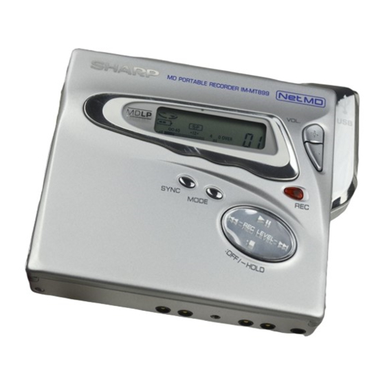
NAMES OF PARTS ............................................................................................................................................................... 5
OPERATION MANUAL .......................................................................................................................................................... 6
DISASSEMBLY .................................................................................................................................................................... 10
REMOVING AND REINSTALLING THE MAIN PARTS ....................................................................................................... 11
ADJUSTMENT ...................................................................................................................................................................... 12
NOTES ON SCHEMATIC DIAGRAM .................................................................................................................................. 28
TYPES OF TRANSISTOR AND DIODE .............................................................................................................................. 28
BLOCK DIAGRAM ............................................................................................................................................................... 29
SCHEMATIC DIAGRAM ...................................................................................................................................................... 30
WIRING SIDE OF P.W.BOARD ........................................................................................................................................... 32
VOLTAGE ............................................................................................................................................................................ 36
WAVEFORMS OF MD CIRCUIT ......................................................................................................................................... 38
WAVEFORMS POINTS ....................................................................................................................................................... 39
TROUBLESHOOTING ......................................................................................................................................................... 40
TROUBLESHOOTING FOR NET MD .................................................................................................................................. 43
PROCEDURES FOR CONNECTION TO A NET MD PLAYER ........................................................................................... 44
FUNCTION TABLE OF IC .................................................................................................................................................... 45
PARTS GUIDE/EXPLODED VIEW
SERVICE MANUAL
PORTABLE MINIDISC RECORDER
MODEL
CONTENTS
SHARP CORPORATION
IM-MT899H/IM-MT899W
IM-MT899H(S)
IM-MT899W(S)
• In the interests of user-safety the set should be restored to its
original condition and only parts identical to those specified be
used.
This document has been published to be used
for after sales service only.
The contents are subject to change without notice.
No. S2208IMMT899H
Page
Table of Contents
Troubleshooting

Related Manuals for Sharp IM-MT899H


Summary of Contents for Sharp IM-MT899H
-
Page 1: Table Of Contents
IM-MT899H/IM-MT899W SERVICE MANUAL No. S2208IMMT899H PORTABLE MINIDISC RECORDER IM-MT899H(S) IM-MT899W(S) MODEL • In the interests of user-safety the set should be restored to its original condition and only parts identical to those specified be used. CONTENTS Page SAFETY PRECAUTION FOR SERVICE MANUAL ....................... 2 SPECIFICATIONS ................................. -
Page 2: Safety Precaution For Service Manual
IM-MT899H/IM-MT899W SAFETY PRECAUTION FOR SERVICE MANUAL Precaution to be taken when replacing and servicing the Laser Pickup. The AEL (Accessible Emission Level) of Laser Power Output for this model is specified to be lower than Class I Requirements. However, the following precautions must be observed during servicing to protect your eyes against exposure to the laser beam. -
Page 3: Specifications
IM-MT899H/IM-MT899W FOR A COMPLETE DESCRIPTION OF THE OPERATION OF THIS UNIT, PLEASE REFER TO THE OPERATION MANUAL. SPECIFICATIONS IM-MT899H Power source: DC 5 V: AC adaptor (AC 230 V, 50/60 Hz) DC 1.5 V: Commercially available, "AA" size (LR6), alkaline battery x 1 DC 1.2 V:... - Page 4 IM-MT899H/IM-MT899W IM-MT899W Power source: DC 5 V: AC adaptor (AC 110 - 240 V, 50/60 Hz) DC 1.5 V: Commercially available, "AA" size (LR6), alkaline battery x 1 DC 1.2 V: Rechargeable Nickel-Metal Hydride battery AD-N55BT x 1 DC 1.5 V:...
-
Page 5: Names Of Parts
IM-MT899H/IM-MT899W NAMES OF PARTS Main unit 1. Synchronised Recording Button 2. Mode Button 3. Volume Buttons 4. Record Button 5. Play/Pause/Stop/Power Off/Hold/Fast Forward/ Fast Reverse Button 6. Rechargeable Battery Cover 7. 2 V DC Input Socket 8. Optical/Line Input Socket 9. -
Page 6: Operation Manual
IM-MT899H/IM-MT899W OPERATION MANUAL Using with the Rechargeable Battery Charging When the rechargeable battery is used for the first time or when you want to use it after a long period of disuse, be sure to charge it fully. Insert the rechargeable battery. - Page 7 IM-MT899H/IM-MT899W Using with the Rechargeable Battery Display of remaining amount of battery Charging time When the unit is set on the charger, the remaining Charging is completed in about 3 hours, and the dis- amount of battery is displayed. play of remaining amount of battery will go out.
- Page 8 Many potential "problems" can be resolved by the owner without calling a service technician. If something seems to be wrong with this product, check the following before calling your authorised SHARP dealer or service centre. The unit does not turn on.
- Page 9 IM-MT899H/IM-MT899W Error Messages ERROR MES- MEANING ERROR MES- MEANING SAGES SAGES BLANK Nothing is recorded. Can'tW Cannot save the TOC information cor- (Replace the disc with a recorded disc.) rectly to a MiniDisc. You tried to operate whilst charging. busy A track is being moved.
-
Page 10: Disassembly
IM-MT899H/IM-MT899W DISASSEMBLY Cares before disassembling (B1) x 2 ø1.4 x 1.5mm When assembling the machine after disassembling or (A1) x 1 repair, observe the following requirements so as to ensure Top Cabinet ø1.4 x 1.5mm safety and performance. 1. Remove the batteries from the machine, and take out the (A1) x 1 mini-disc. -
Page 11: Removing And Reinstalling The Main Parts
IM-MT899H/IM-MT899W REMOVING AND REINSTALLING THE MAIN PARTS Remove the MD mechanism according to the disassembling methods 1 to 4. (See Page 10.) How to remove the spindle motor (See Fig. 11-1.) (A2) x 3 1. Remove the solder joints (A1) x 4 of flexible PWB. -
Page 12: Adjustment
IM-MT899H/IM-MT899W ADJUSTMENT Test disc MD adjustment needs two types of disc, namely recording disc (low reflection disc) and playback-only disc (high reflection disc). Type Test disc Parts No. High reflection disc MMD-110 (TEAC Test MD) 88GMMD-110 Low reflection disc MMD-213A (TEAC Test MD) - Page 13 IM-MT899H/IM-MT899W 1. AUTO 1 Mode • Perform preliminary automatic adjustment. 6. TEST-REC Mode • Perform continuous recording from the • If the combination of the mechanism and specified address. pickup PWB is changed, be sure to start • Change of record laser output. (servo gain is adjustment in this mode.
- Page 14 IM-MT899H/IM-MT899W • When the MENU button is pressed in the continuous playback mode, the number of jump lines changes as follows. 1 — 10 — 100 step — 1 — * After the number of tracks to be jumped is displayed for 1 second, the address will reappear.[ T R_ ] •...
- Page 15 IM-MT899H/IM-MT899W ** = 41 Error List “Er-MD41” is displayed when an error occurs while writing U-TOC Can't (*) for trial (recorders only). Focus retraction (Data error found when reading data after it is written.) Servo adjustment There may be a problem with the recording head, recording signal Search convergence generating circuit including the system LSI, or pickup laser.
- Page 16 IM-MT899H/IM-MT899W EEPROM DATA LIST (EEPROM version : C) Tracking setting Fucus setting Item display Item display Set values Set values FG1 _ T1P _ FG2 _ TSA _ FF0 _ Spindle setting FF1 _ Item display FF2 _ Set values...
- Page 17 IM-MT899H/IM-MT899W Sled setting Control setting Item display Set values Item display Set values BRE _ CT0 _ BRW _ CT1 _ SRS _ CT2 _ CT3 _ BASS setting USA _ Item display RCE _ Set values X2T _ B1A _...
- Page 18 IM-MT899H/IM-MT899W Do the following when replacing the mechanism, the pickup, the EEPROM (IC402), the LSI(IC201) or the main PWB unit. Enter the test mode, move the pickup to the most internal periphery and execute AUTO1. (Use the disc of MMD-213A.)
- Page 19 IM-MT899H/IM-MT899W Change of Test Mode Menus MODE/ DISPLAY T E S T : Test mode stop SKIP UP SKIP DOWN Slide external Slide internal periphery move periphery move SKIP DOWN : Pre-automatic adjustment menu A U T O 1 SKIP UP...
- Page 20 IM-MT899H/IM-MT899W Servo ATT Auto Adjustment A U T O 2 : ATT auto adjustment menu PLAY A T 2 : During ATT auto adjustment Adjustment error A D J . N G Normal end : ATT adjustment error (adjustment value output) A D J .
- Page 21 IM-MT899H/IM-MT899W * In the continuous playback state the number of jump lines changes as follows shown the [MENU] button is pressed. 1 (initial value) MENU MENU 1 T R 1 0 T R 1 0 0 s t p 100 st ep...
- Page 22 IM-MT899H/IM-MT899W Servo Pre-Manual Adjustment M A N U 1 : Pre-Manual Adjustment menu PLAY : Temperature code indication T M P : Temperature code SKIP UP SKIP DOWN : A signal offset (AINO) measurement : Measurement value SKIP UP SKIP DOWN...
- Page 23 IM-MT899H/IM-MT899W • ABMAXO measurement value : A-ATT (focus) tentative setting : B-ATT (focus) tentative setting GROUP/CLEAR GROUP/CLEAR : ABMAXO measurement value indication "1" Mark lighting • LPFABO measurement value : A-ATT (focus) tentative setting : B-ATT (focus) tentative setting GROUP/CLEAR...
- Page 24 IM-MT899H/IM-MT899W : High-reflection pit section B-ATT (focus) setting : Low-reflection pit section B-ATT (focus) setting : Low-reflection groove section B-ATT (focus) setting : ATT setting MODE/ PLAY DISPLAY : Continuous playback (pit section) S Q # # # # : Continuous playback (groove section)
- Page 25 IM-MT899H/IM-MT899W Servo Pre-adjustment Value Check R S L T 1 : Pre-adjustment Value Check menu PLAY : A signal offset measurement value (setting) SKIP UP SKIP DOWN : B signal offset measurement value (setting) SKIP UP SKIP DOWN : E signal offset measurement value (setting)
- Page 26 IM-MT899H/IM-MT899W ATT Setting Check R S L T 2 : ATT Setting Check menu PLAY : Pit section E-ATT (tracking) setting SKIP UP SKIP DOWN : Pit section F-ATT (tracking) setting SKIP UP SKIP DOWN : Groove section E-ATT (tracking) setting...
- Page 27 IM-MT899H/IM-MT899W Conti n ued from previ o us page SKIP UP SKIP DOWN : Error history 6 indication E 6 $ $ $ $ : Error code SKIP UP SKIP DOWN : Error history 7 indication E 7 $ $...
-
Page 28: Notes On Schematic Diagram
IM-MT899H/IM-MT899W NOTES ON SCHEMATIC DIAGRAM • Resistor: To differentiate the units of resistors, such symbol as K and REF. NO DESCRIPTION POSITION M are used: the symbol K means 1000 ohm and the symbol SW401 EJECT OFF—ON M means 1000 kohm and the resistor without any symbol is... -
Page 29: Block Diagram
IM-MT899H/IM-MT899W J702 MIC IN J701 J703 REMOTE JK301 OPTICAL LINE (READY FOR J801 PLUG/IN POWER) HEADPHONES CONTROL DC JACK +3.1V VCC_SERVO_ON 2,51,54,58 85,86,88-90, 67,68,70 91,92 8-14,16-19, 56-59 25,31,32,97 64,71,110,118 6-12 84,87 Figure 29 BLOCK DIAGRAM – 29 –... -
Page 30: Schematic Diagram
IM-MT899H/IM-MT899W MAIN PWB-A PLAYBACK SIGNAL RECORD SIGNAL C109 C111 CK200 IC101 IR3R58M CK139 RF SIGNAL PROCESSOR 1234 BIAS VCC1 C131 EFMAGC CK111 C211 5P(CH) CK112 ADAGI IC30 CK113 C132 DIFF TC7SH ADAGC 0.22 C102 CK114 ADIPNF GATE CK108 REFI ADIPO... - Page 31 IM-MT899H/IM-MT899W LCD/KEY PWB-B CNA01 VLCD LCD ASS'Y SWA01 RECORD (238) PLAY SWA02 PLAY R444 STOP SWA03 STOP SKIP UP SWA04 SKIP UP 6 5 4 RA02 RA01 R446 2.2K SKIP DOWN SWA05 SKIP DOWN 1.5K RA03 3.3K VOL+ SWA06 VOLUME +...
-
Page 32: Wiring Side Of P.w.board
IM-MT899H/IM-MT899W MAIN PWB-A (TOP VIEW) C113 C111 R822 C110 R251 C114 R111 C108 R256 CK112 C131 SW402 R254 R257 OPEN/CLOSE C132 R455 R132 OPTICAL PICKUP(19) C100 IC101 R131 R274 C272 R133 C165 R456 BATTERY COVER BRACKET,+ (214) R273 R134 R277... - Page 33 IM-MT899H/IM-MT899W MAIN PWB-A (BOTTOM VIEW) L100 C109 R812 TP103 TP115 TP117 R802 R164 C801 TP458 R163 D801 R819 R421 D891 R818 C817 R402 R204 C203 TP456 C171 Q252 C846 R263 Q261 C404 R261 R842 L601 R262 C847 L202 TP415 C838...
- Page 34 IM-MT899H/IM-MT899W SWA06 VOLUME + CNA01 SWA07 VOLUME – LCD ASS'Y (238) SWA08 RA06 RA03 MODE SWA01 RECORD SWA02 PLAY RA02 SWA03 STOP RA01 SWA04 SKIP UP LCD/KEY PWB-B (TOP VIEW) FPC01 MAIN PWB-A CN451 P32 3-E LCD/KEY PWB-B (BOTTOM VIEW) : Through-hole where the top and bottom patterns are connected.
- Page 35 IM-MT899H/IM-MT899W OPTICAL PICKUP(19) M903 LIFT MOTOR M901 SPINDLE MOTOR CN101 TO MAIN PWB P32 4-C MECHANISM FLEXIBLE PWB(17) M902 SLED MOTOR MAGNETIC HEAD(18) TO MAIN PWB CN601 P32 5-E Figure 35 WIRING SIDE OF P.W.BOARD (4/4) – 35 –...
-
Page 36: Voltage
IM-MT899H/IM-MT899W VOLTAGE IC301 IC401 IC101 IC201 IC501 VOLTAGE PIN VOLTAGE PIN VOLTAGE VOLTAGE VOLTAGE VOLTAGE VOLTAGE VOLTAGE 3.12 V 3.12 V 0.15 V 0.79 V 3.06 V 0.15 V 0.1 V 3.07 V 2.49 V 0.15 V 3.12 V 3.07 V 3.07 V... - Page 37 IM-MT899H/IM-MT899W IC701 IC703 IC771 IC821 IC841 IC851 IC871 VOLTAGE VOLTAGE VOLTAGE VOLTAGE VOLTAGE VOLTAGE VOLTAGE 1.2 V 2.04 V 1.2 V 1.24 V 2.49 V 2.49 V 2.46 V 0.8 V 2.46 V 0.4 V – 0.4 V – 1.26 V...
-
Page 38: Waveforms Of Md Circuit
IM-MT899H/IM-MT899W WAVEFORMS OF MD CIRCUIT Stopped Stopped 1994 / 12 / 15 22:54:19 1994 / 12 / 16 00:24:17 Stopped 1994 / 12 / 16 01:03:40 CH1=1 mV CH2=500 mV CH3=5 V CH4=2 V 50 ms/div CH1=2 V CH2=2 V... -
Page 39: Waveforms Points
IM-MT899H/IM-MT899W WAVEFORMS POINTS MAIN PWB-A (BOTTOM VIEW) L841 XL401 IC703 Q252 TP120 TP121 L602 L851 L604 L609 L603 L601 L821 CK108 TP201A IC101 CN601 IC201 IC601 IC501 IC402 CN451 IC401 IC701 IC202 IC301 MAIN PWB-A (TOP VIEW) – 39 –... -
Page 40: Troubleshooting
IM-MT899H/IM-MT899W TROUBLESHOOTING Use the test mode which indicates trouble causes before repairing the unit. This mode records maximum 10 past error causes as codes. Refer them for repairing. Preparations If dusts and foreign materials are accumulated on the pickup lens, playback sounds can be skipped or the TOC (Table of Contans) can't be displayed. - Page 41 IM-MT899H/IM-MT899W • Abnormal display Is waveform output from CN451 pins 3 to 5 ? Is waveform output from pins 2, 54 and 58 of IC401 ? Are the pin 2 (VCC) and pin 12 (GND) normal ? Check between IC401 and Check the periphery of IC401.
- Page 42 IM-MT899H/IM-MT899W • Recording/playback operation 1. Insert a low reflection disc, and ascertain audio output by normal playback, and then set TEST REC mode. Change MSL from 00H to 80H by the control setting of EEPROM. After completing the operation, return in to 00H.
-
Page 43: Troubleshooting For Net Md
IM-MT899H/IM-MT899W TROUBLESHOOTING FOR NET MD After checking that recording and playback are normally operated on this unit, try the check-in/check-out operation. Preparations After checking "Necessary system configurations" described in the service manual, install Jukebox according to "Software installation" and "PC connection". After completing the installation, start Jukebox. -
Page 44: Procedures For Connection To A Net Md Player
IM-MT899H/IM-MT899W PROCEDURES FOR CONNECTION TO A NET MD PLAYER Connect the USB cable. All the connection of the PC should be made and its power should be turned on. The player should be turned on (the indicator lights up). Checking the connection of the USB cable. -
Page 45: Function Table Of Ic
IM-MT899H/IM-MT899W FUNCTION TABLE OF IC IC401 RH-iX2992AFZZ : System Microcomputer (IX2992AF) (1/3) Port Name Terminal Name Input/Output Function Pin No. — Positive power supply DSPSTB Output Main unit display strobe output EEPD Input/Output EEPROM serial data input/output EEPK Output EEPROM serial clock output... - Page 46 IM-MT899H/IM-MT899W IC401 RH-iX2992AFZZ : System Microcomputer (IX2992AF) (2/3) Port Name Terminal Name Input/Output Function Pin No. SCK0 SCK0 Output Serial clock output (unused) SCK1 DSPSCK Output Output for main unit display data clock — Ground potential DISCPR Input Disc recording prohibition switch input...
- Page 47 IM-MT899H/IM-MT899W IC401 RH-iX2992AFZZ : System Microcomputer (IX2992AF) (3/3) Pin No. Port Name Terminal Name Input/Output Function DFCKC Output Security IC clock input ON/OFF TCLKB SPIN Input Input for spindle motor FG pulse detection TCLKA Input Track cross signal/focus drive detection...
- Page 48 IM-MT899H/IM-MT899W –– MEMO –– – 48 –...
- Page 49 “HOW TO ORDER REPLACEMENT PARTS” To have your order filled promptly and correctly, please furnish the For U.S.A. only following information. Contact your nearest SHARP Parts Distributor to order. 1. MODEL NUMBER 2. REF. No. 3. PART NO. 4. DESCRIPTION For location of SHARP Parts Distributor, Please call Toll-Free;...
- Page 50 IM-MT899H/IM-MT899W PRICE PRICE DESCRIPTION PARTS CODE DESCRIPTION PART CODE RANK RANK INTEGRATED CIRCUITS D841 VHDFS1J2EA/-1 AC Silicon,FS1J2EA D842 VHDHRB0103B-1 AC Silicon,HRB0103B D843 VHD1SS372//-1 AD Silicon,1SS372 IC101 VHIIR3R58M/-1 AM RF Signal Processor,IR3R58M D851,852 VHDF10J2E//-1 AC Silicon,F10J2E IC201 VHILR37818+-1 BL Endec/Servo/Atrac,LR37818 D861,862...
- Page 51 IM-MT899H/IM-MT899W PRICE PRICE DESCRIPTION PART CODE PARTS CODE DESCRIPTION RANK RANK AC 1 µF,6.3V C313,314 VCCCCZ1HH150J AA 15 pF (CH),50V C913 VCKYCY0JB105K AB 0.1 µF,16V C316 VCKYCZ1HB221K AB 220 pF,50V CA01,02 VCKYCY1CB104K C351 VCCCCY1HH470J AA 47 pF (CH),50V AC 1 µF,6.3V...
- Page 52 IM-MT899H/IM-MT899W PRICE PRICE DESCRIPTION PART CODE PARTS CODE DESCRIPTION RANK RANK R446 VRS-CZ1JB821J AA 820 ohms,1/16W R884,885 VRS-CZ1JB103J AA 10 kohm,1/16W R447 VRS-CZ1JB103J AA 10 kohm,1/16W R886 VRS-CZ1JB562J AB 5.6 kohms,1/16W R451 VRS-CZ1JB102J AB 1 kohm,1/16W R887~889 VRS-CZ1JB102J AB 1 kohm,1/16W...
- Page 53 92LGCARD1266E1 J AC Warranty Card [For Australia/ GCOVH8001AWSA J AE Cover,USB Terminal Newzealand] GFTAB1037AWSA J AF Cover,Battery HDECQ0828AWSA J AX Decoration Plate ACCESSORIES/PACKING PARTS (IM-MT899H) JKNBZ0840AWSA AG Operation Button,A JKNBZ0841AWSC AK Operation Button,B JKNBZ0842AWSA AE Knob,Eject GCASZ0002AWSA J AL Battery Case...
- Page 54 IM-MT899H/IM-MT899W 501x3 504x2 506x2 M901 M902 M903 Figure 5 MD MECHANISM EXPLODED VIEW – 5 –...
- Page 55 IM-MT899H/IM-MT899W MD MECHANISM 601x2 601x2 237x4 230x2 MAIN PWB 602x2 LCD/KEY PWB 603x2 604x2 Figure 6 CABINET EXPLODED VIEW – 6 –...
-
Page 56: Packing Method (For U.k. Only)
Pad, AC Adaptor SPAKZ0490AWZZ Pad, Operation Manual TCAUZ0144AWZZ User Support Caution © COPYRIGHT 2002 BY SHARP CORPORATION SHARP CORPORATION ALL RIGHTS RESERVED. AV Systems Group Audio Systems Division No part of this publication may be reproduced, Higashihiroshima, Hiroshima 739-0192, Japan...