Siemens SIMATIC S7-1500 Manual
Analog input module ai 8xu/i hs
Hide thumbs
Also See for SIMATIC S7-1500:
- Function manual (402 pages) ,
- System manual (393 pages) ,
- Manual (188 pages)

Related Manuals for Siemens SIMATIC S7-1500


Summary of Contents for Siemens SIMATIC S7-1500
- Page 1 SIMATIC S7-1500 Analog input module AI 8xU/I HS (6ES7531-7NF10-0AB0) Manual Edition 07/2014 Answers for industry.
- Page 2 ___________________ Analog Input Module AI 8xU/I HS Preface (6ES7531-7NF10-0AB0) ___________________ Documentation guide ___________________ Product overview SIMATIC ___________________ Wiring S7-1500/ET 200MP ___________________ Analog Input Module AI 8xU/I HS Parameters/address space (6ES7531-7NF10-0AB0) ___________________ Interrupts/diagnostics alarms Manual ___________________ Technical specifications ___________________ Dimensional drawing ___________________ Parameter data records ___________________...
- Page 3 Note the following: WARNING Siemens products may only be used for the applications described in the catalog and in the relevant technical documentation. If products and components from other manufacturers are used, these must be recommended or approved by Siemens. Proper transport, storage, installation, assembly, commissioning, operation and maintenance are required to ensure that the products operate safely and without any problems.
-
Page 4: Preface
Preface Purpose of the documentation This manual supplements the system manuals: ● S7-1500 Automation System ● ET 200MP Distributed I/O System Functions that relate in general to the systems are described in these system manuals. The information provided in this manual and in the system/function manuals supports you in commissioning the systems. - Page 5 Siemens accepts no liability for the use of the open source software over and above the intended program sequence, or for any faults caused by modifications to the software.
-
Page 6: Table Of Contents
Table of contents Preface ..............................3 Documentation guide ..........................6 Product overview ............................ 8 Properties ..........................8 Wiring ..............................11 Parameters/address space ........................16 Measuring types and ranges ....................16 Parameters ..........................17 Declaration of parameters ...................... 18 Address space ........................20 Interrupts/diagnostics alarms ......................... -
Page 7: Documentation Guide
This arrangement enables you to access the specific content you require. Basic information System Manual and Getting Started describe in detail the configuration, installation, wiring and commissioning of the SIMATIC S7-1500 and ET 200MP systems. The STEP 7 online help supports you in the configuration and programming. Device information Manuals contain a compact description of the module-specific information, such as properties, terminal diagrams, characteristics, technical specifications. - Page 8 Documentation guide Manual Collection S7-1500 / ET 200MP The Manual Collection contains the complete documentation on the SIMATIC S7-1500 automation system and the ET 200MP distributed I/O system gathered together in one file. You can find the Manual Collection on the Internet (http://support.automation.siemens.com/WW/view/en/86140384).
-
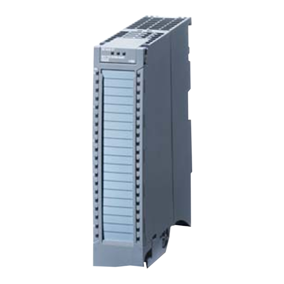
Page 9: Product Overview
Product overview Properties Article number 6ES7531-7NF10-0AB0 View of the module Figure 2-1 View of the AI 8xU/I HS module Analog Input Module AI 8xU/I HS (6ES7531-7NF10-0AB0) Manual, 07/2014, A5E03484886-AC... - Page 10 Product overview 2.1 Properties Properties The module has the following technical properties: ● 8 analog inputs ● Voltage or current measuring type can be set per channel ● Resolution 16 bits including sign ● Configurable diagnostics (per channel) ● Hardware interrupt on limit violation can be set per channel (two low and two high limits per channel) ●...
- Page 11 The following component must be ordered separately: Front connectors, including potential jumpers and cable ties You can find more information on accessories in the S7-1500 Automation System system manual (http://support.automation.siemens.com/WW/view/en/59191792) and the ET 200MP Distributed I/O System system manual (http://support.automation.siemens.com/WW/view/en/59193214).
-
Page 12: Wiring
The section below includes the block diagram of the module and various wiring options. For more information on front connector wiring and creating cable shields, for example, refer to the "Wiring" section in the S7-1500 Automation System (http://support.automation.siemens.com/WW/view/en/59191792) and ET 200MP Distributed I/O System (http://support.automation.siemens.com/WW/view/en/59193214) system manuals. - Page 13 Wiring Pin assignment for the power supply element The power supply element is plugged onto the front connector for powering the analog module. Wire the supply voltage to terminals 41 (L+) and 44 (M). Use terminals 42 (L+) and 43 (M) to loop the potential to the next module. Figure 3-1 Power supply element wiring Analog Input Module AI 8xU/I HS (6ES7531-7NF10-0AB0)
- Page 14 Wiring Block diagram and pin assignment for voltage measurement The example in the figure below shows the pin assignment for a voltage measurement. ① Analog-to-Digital Converter (ADC) ② Backplane bus interface ③ Supply voltage via power supply element ④ Equipotential bonding cable (optional) Figure 3-2 Block diagram and pin assignment for voltage measurement Analog Input Module AI 8xU/I HS (6ES7531-7NF10-0AB0)
- Page 15 Wiring Block diagram and pin assignment for 4-wire transmitter for current measurement The example in the following figure shows the pin assignment for current measurement with 4-wire transmitters. ① Wiring 4-wire transmitter ② Analog-to-Digital Converter (ADC) ③ Backplane bus interface ④...
- Page 16 Wiring Block diagram and pin assignment for 2-wire transmitter for current measurement The example in the following figure shows the pin assignment for current measurement with 2-wire transmitters. ① Wiring 2-wire transmitter ② Analog-to-Digital Converter (ADC) ③ Backplane bus interface ④...
-
Page 17: Parameters/Address Space
Parameters/address space Measuring types and ranges Introduction The module is set to voltage measuring type with measuring range ±10 V by default. You need to reassign the module parameters with STEP 7 if you want to use a different measuring type or range. The following table shows the measuring types and the respective measuring range. -
Page 18: Parameters
Parameters/address space 4.2 Parameters Parameters Parameters of the AI 8xU/I HS When you assign the module parameters in STEP 7, you use various parameters to specify the module properties. The following table lists the configurable parameters. The effective range of the configurable parameters depends on the type of configuration. The following configurations are possible: ●... -
Page 19: Declaration Of Parameters
Parameters/address space 4.3 Declaration of parameters Parameters Range of values Default Parameter as- Scope with configuration software, e.g., setting signment in RUN STEP 7 (TIA Portal) GSD file GSD file PROFINET IO PROFIBUS DP Yes/No Channel Hardware interrupt • low limit 1 Yes/No Channel Hardware interrupt... - Page 20 Parameters/address space 4.3 Declaration of parameters Smoothing The individual measured values are smoothed using filtering. The smoothing can be set in 4 levels. Smoothing time = number of module cycles (k) x cycle time of the module. The following figure shows after how many module cycles the smoothed analog value is almost 100%, depending on the set smoothing.
-
Page 21: Address Space
Parameters/address space 4.4 Address space Address space The module can be configured differently in STEP 7; see following table. Depending on the configuration, additional/different addresses are assigned in the process image of the inputs. Configuration options of AI 8xU/I HS You can configure the module with STEP 7 (TIA Portal) or with a GSD file. - Page 22 Parameters/address space 4.4 Address space Address space of AI 8xU/I HS The following figure shows the address space allocation for the configuration as 8-channel module. You can freely assign the start address for the module. The addresses of the channels are derived from the start address. "IB x", for example represents the module start address input byte x.
- Page 23 Parameters/address space 4.4 Address space Address space for configuration as 8 x 1-channel AI 8xU/I HS S QI For the configuration as a 8 x 1-channel module, the channels of the module are divided into multiple submodules. The submodules can be assigned to different IO controllers when the module is used in a shared device.
- Page 24 Parameters/address space 4.4 Address space Address space for configuration as 1 x 8-channel AI 8xU/I HS MSI The channels 0 to 7 of the module are copied in up to four submodules with configuration 1 x 8-channel module (Module-internal shared input, MSI). Channels 0 to 7 are then available with identical input values in different submodules.
- Page 25 Parameters/address space 4.4 Address space The following figure shows the assignment of the address space with submodules 1 and 2. Figure 4-4 Address space for configuration as 1 x 8-channel AI 8xU/I HS MSI with value status Analog Input Module AI 8xU/I HS (6ES7531-7NF10-0AB0) Manual, 07/2014, A5E03484886-AC...
- Page 26 Parameters/address space 4.4 Address space The following figure shows the assignment of the address space with submodules 3 and 4. Figure 4-5 Address space for configuration as 1 x 8-channel AI 8xU/I HS MSI with value status Analog Input Module AI 8xU/I HS (6ES7531-7NF10-0AB0) Manual, 07/2014, A5E03484886-AC...
-
Page 27: Interrupts/Diagnostics Alarms
Interrupts/diagnostics alarms Status and error displays LED displays The following figure shows the LED displays (status and error displays) of AI 8xU/I HS. Figure 5-1 LED displays of the module AI 8xU/I HS Analog Input Module AI 8xU/I HS (6ES7531-7NF10-0AB0) Manual, 07/2014, A5E03484886-AC... - Page 28 Interrupts/diagnostics alarms 5.1 Status and error displays Meaning of the LED displays The following tables explain the meaning of the status and error displays. Remedial measures for diagnostic alarms can be found in section Diagnostic alarms. RUN and ERROR LED Table 5- 1 Status and error displays RUN and ERROR Meaning...
- Page 29 Interrupts/diagnostics alarms 5.1 Status and error displays CHx LED Table 5- 3 CHx status display LED CHx Meaning Remedy Channel disabled Channel configured and OK. Channel is configured (channel error pending). Check the wiring. Diagnostic alarm: e.g. wire break Disable diagnostics. See also Diagnostics alarms (Page 31) Analog Input Module AI 8xU/I HS (6ES7531-7NF10-0AB0)
-
Page 30: Interrupts
Interrupts/diagnostics alarms 5.2 Interrupts Interrupts Analog input module AI 8xU/I HS supports the following diagnostic and hardware interrupts. Diagnostic interrupt The module generates a diagnostic interrupt at the following events: ● Missing supply voltage L+ ● Wire break ● Overflow ●... - Page 31 Interrupts/diagnostics alarms 5.2 Interrupts Reaction when reaching limits 1 and 2 at the same time If the two high limits 1 and 2 are reached at the same time, the module always signals the hardware interrupt for high limit 1 first. The configured value for high limit 2 is irrelevant. After processing the hardware interrupt for high limit 1, the module triggers the hardware interrupt for high limit 2.
-
Page 32: Diagnostics Alarms
Interrupts/diagnostics alarms 5.3 Diagnostics alarms Diagnostics alarms A diagnostics alarm is output for each diagnostics event and the ERROR LED flashes on the module. The diagnostics alarms can, for example, be read from the diagnostics buffer of the CPU. You can evaluate the error codes with the user program. If the module is operated distributed with PROFIBUS DP in an ET 200MP system, you have the option to read out diagnostics data with the instruction RDREC or RD_REC using data record 0 and 1. -
Page 33: Technical Specifications
Technical specifications Technical specifications of the AI 8xU/I HS 6ES7531-7NF10-0AB0 Product type designation AI 8xU/I HS General information Hardware version Firmware version V2.0.0 Product function I&M data Yes; IM0 to IM3 Engineering with STEP 7 TIA Portal can be configured/integrated V12.0 / V12.0 as of version STEP 7 can be configured/integrated as of version as of V5.5 SP3 / -... - Page 34 Technical specifications 6ES7531-7NF10-0AB0 Input ranges (rated values), voltages 1 V to 5 V Input resistance (1 V to 5 V) 50 kΩ -10 V to +10 V Input resistance (-10 V to +10 V) 100 kΩ -5 V to +5 V Input resistance (-5 V to +5 V) 50 kΩ...
- Page 35 Technical specifications 6ES7531-7NF10-0AB0 Operational limit in overall temperature range Voltage, relative to input range ± 0.3 % Current, relative to input range ± 0.3 % Basic error limit (operational limit at 25 °C) Voltage, relative to input range ± 0.2 % Current, relative to input range ±...
- Page 36 Technical specifications 6ES7531-7NF10-0AB0 Ambient conditions Operating temperature Horizontal mounting position, min. 0 °C Horizontal mounting position, max. 60 °C Vertical mounting position, min. 0 °C Vertical mounting position, max. 40 °C Distributed mode Prioritized startup Dimensions Width 35 mm Height 147 mm Depth 129 mm...
-
Page 37: Dimensional Drawing
Dimensional drawing This appendix contains the dimensional drawing of the module installed on a mounting rail and with a shield bracket. Always adhere to the specified dimensions for installations in cabinets, control rooms, etc. Figure A-1 Dimensional drawing of the AI 8xU/I HS module Analog Input Module AI 8xU/I HS (6ES7531-7NF10-0AB0) Manual, 07/2014, A5E03484886-AC... - Page 38 Dimensional drawing Figure A-2 Dimensional drawing of the AI 8xU/I HS module, side view with open front panel Analog Input Module AI 8xU/I HS (6ES7531-7NF10-0AB0) Manual, 07/2014, A5E03484886-AC...
-
Page 39: Parameter Data Records
Parameter data records Parameter assignment and structure of the parameter data records The data records of the module have an identical structure, regardless of whether you configure the module with PROFIBUS DP or PROFINET IO. Dependencies for configuration with GSD file When configuring the module with a GSD file, remember that the settings of some parameters are dependent on each other. - Page 40 0 and 1. You can find more information in the Interrupts section of the PROFIBUS DP interface module device manual on the Internet (http://support.automation.siemens.com/WW/view/en/78324181). Assignment of data record and channel For the configuration as a 1 x 8-channel module, the parameters are located in data records 0 to 7 and are assigned as follows: ●...
- Page 41 Parameter data records B.1 Parameter assignment and structure of the parameter data records Data record structure The example in the following figure shows the structure of data record 0 for channel 0. The structure of channels 1 to 7 is identical. The values in byte 0 and byte 1 are fixed and may not be changed.
- Page 42 Parameter data records B.1 Parameter assignment and structure of the parameter data records Figure B-2 Structure of data record 0: Bytes 7 to 27 Analog Input Module AI 8xU/I HS (6ES7531-7NF10-0AB0) Manual, 07/2014, A5E03484886-AC...
- Page 43 Parameter data records B.1 Parameter assignment and structure of the parameter data records Codes for measuring types The following table lists all measuring types of the analog input module along with their codes. Enter these codes at byte 2 of the respective data record (see previous figure). Table B- 2 Code for the measuring type Measuring type...
- Page 44 Parameter data records B.1 Parameter assignment and structure of the parameter data records Analog Input Module AI 8xU/I HS (6ES7531-7NF10-0AB0) Manual, 07/2014, A5E03484886-AC...
-
Page 45: Representation Of Analog Values
Representation of analog values Introduction This chapter shows the analog values for all measuring ranges supported by the AI 8xU/I HS analog module. Measured value resolution Each analog value is written left aligned to the tags. The bits marked with "x" are set to "0". Table C- 1 Resolution of the analog values Resolution in bits... -
Page 46: Representation Of Input Ranges
Representation of analog values C.1 Representation of input ranges Representation of input ranges The following tables set out the digitalized representation of the input ranges by bipolar and unipolar range. The resolution is 16 bits. Table C- 2 Bipolar input ranges Units Measured Data word... -
Page 47: Representation Of Analog Values In Voltage Measuring Ranges
Representation of analog values C.2 Representation of analog values in voltage measuring ranges Representation of analog values in voltage measuring ranges The following tables list the decimal and hexadecimal values (codes) of the possible voltage measuring ranges. Table C- 4 Voltage measuring range ±10 V and ±5 V Values Voltage measuring range... -
Page 48: Representation Of Analog Values In The Current Measuring Ranges
Representation of analog values C.3 Representation of analog values in the current measuring ranges Representation of analog values in the current measuring ranges The following tables list the decimal and hexadecimal values (codes) of the possible current measuring ranges. Table C- 6 Current measuring range ±20 mA Values Current measuring range... -
Page 49: Measured Values For Wire Break Diagnostic
Representation of analog values C.4 Measured values for wire break diagnostic Measured values for wire break diagnostic Measured values on diagnostic event "wire break", dependent on diagnostics enables Error events initiate a diagnostics entry and trigger a diagnostics interrupt if configured accordingly. -
Page 50: Open Source Software
License Conditions and Disclaimers for Open Source Software and other Licensed Software In the product "Digital Modules, Analog Modules, Technological Modules, Communication Modules and Power Supply Modules of the SIMATIC S7-1500, ET 200MP", Copyright Siemens AG, 2013 - 2014 (hereinafter "Product"), the following Open Source Software is used either unchanged or in a form that we have modified, and additionally the other License Software noted below. - Page 51 Open Source Software Analog Input Module AI 8xU/I HS (6ES7531-7NF10-0AB0) Manual, 07/2014, A5E03484886-AC...
- Page 52 Open Source Software Analog Input Module AI 8xU/I HS (6ES7531-7NF10-0AB0) Manual, 07/2014, A5E03484886-AC...
- Page 53 Open Source Software Analog Input Module AI 8xU/I HS (6ES7531-7NF10-0AB0) Manual, 07/2014, A5E03484886-AC...
- Page 54 Open Source Software Analog Input Module AI 8xU/I HS (6ES7531-7NF10-0AB0) Manual, 07/2014, A5E03484886-AC...
- Page 55 Open Source Software Analog Input Module AI 8xU/I HS (6ES7531-7NF10-0AB0) Manual, 07/2014, A5E03484886-AC...
- Page 56 Open Source Software Analog Input Module AI 8xU/I HS (6ES7531-7NF10-0AB0) Manual, 07/2014, A5E03484886-AC...
- Page 57 Open Source Software Analog Input Module AI 8xU/I HS (6ES7531-7NF10-0AB0) Manual, 07/2014, A5E03484886-AC...
- Page 58 Open Source Software Analog Input Module AI 8xU/I HS (6ES7531-7NF10-0AB0) Manual, 07/2014, A5E03484886-AC...
- Page 59 Open Source Software Analog Input Module AI 8xU/I HS (6ES7531-7NF10-0AB0) Manual, 07/2014, A5E03484886-AC...
- Page 60 Open Source Software Analog Input Module AI 8xU/I HS (6ES7531-7NF10-0AB0) Manual, 07/2014, A5E03484886-AC...
- Page 61 Open Source Software Analog Input Module AI 8xU/I HS (6ES7531-7NF10-0AB0) Manual, 07/2014, A5E03484886-AC...