Bosch INTEGRUS User Manual
Wireless language distribution system
Hide thumbs
Also See for INTEGRUS:
- Operation manual (94 pages) ,
- Installation and operation manual (90 pages) ,
- Installation and operating manual (60 pages)
Table of Contents
Quick Links
Table of Contents

Related Manuals for Bosch INTEGRUS


Summary of Contents for Bosch INTEGRUS
- Page 1 INTEGRUS Wireless Language Distribution System User manual...
-
Page 3: Table Of Contents
The footprint of the radiator 4.2.3 Ambient lighting 4.2.4 Objects, surfaces and reflections 4.2.5 Position the radiators 4.2.6 Overlapping footprints and black spots Plan an Integrus infrared radiation system 4.3.1 Rectangular footprints 4.3.2 Plan radiators 4.3.3 Cabling Installation Transmitter OMNEO Medium and high power radiators 5.2.1... - Page 4 Imperial values of radiators with hardware version higher than 2.00 10.5.3 Metric values of radiators with hardware version lower than 2.00. 10.5.4 Imperial values of radiators with hardware version lower than 2.00. Support services and Bosch Academy 2023-01 | V01 | Bosch Security Systems B.V. User manual...
-
Page 5: Safety
Operation of this equipment in a residential area is likely to cause harmful interference in which case the user will be required to correct the interference at his own expense. Bosch Security Systems B.V. 2023-01 | V01 | User manual... -
Page 6: About This Manual
The purpose of this document is to provide information required for installing, configuring, operating, maintaining and troubleshooting an Integrus Language Distribution System. Intended audience This document is intended for installers and users of an Integrus Language Distribution System. Related documentation –... -
Page 7: Alerts And Notice Signs
For information on getting permission for reprints and excerpts, contact Bosch Security Systems B.V.. The content and illustrations are subject to change without prior notice. -
Page 8: System Overview
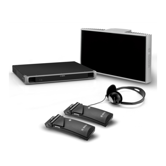
INTEGRUS System overview INTEGRUS is a system for wireless distribution of audio signals through infrared radiation. It can be used in a simultaneous interpretation system for international conferences where multiple languages are used. To enable all participants to understand the discussion, interpreters simultaneously translate the speaker's language as required. - Page 9 This device allows the participants to easily choose their preferred language. 16. IR distribution: – Through infrared distribution, the signals from the INT-TXO are transmitted to the radiators in the room. Bosch Security Systems B.V. 2023-01 | V01 | User manual...
-
Page 10: Transmitter Omneo
And the LBB4560/50 Charger cabinet for 56x LBB4540 for permanent systems Transmitter OMNEO The INT-TXO is the central element in the INTEGRUS system that allows INTEGRUS to interact with the DICENTIS Conference System. The INT-TXO modulates the signals into carrier waves and transmits them to the radiators in the room. - Page 11 – Green: Master mode. – Blinking green: For a future release. – Amber: Slave mode. – Blinking amber: Transmitter not (yet) connected to a radiator. – Blinking green/amber: General error. Bosch Security Systems B.V. 2023-01 | V01 | User manual...
- Page 12 Reset button: Press and hold for 10 seconds to reset the device to factory settings. Emergency terminal block socket for distribution of emergency messages to all channels. Audio In: XLR socket distribute audio to all channels. Chassis ground. 2023-01 | V01 | Bosch Security Systems B.V. User manual...
-
Page 13: Radiators
IREDs becomes too high. Front view Red LED Amber LED Status Standby mode. Transmitting. Blinking At switch-on: Initializing signal equalization. During operation: Temperature protection mode. IRED panel failure. Bosch Security Systems B.V. 2023-01 | V01 | User manual... - Page 14 Output power selection switch: Switch the radiators between full and half-power operation. Delay compensation switches: Two switches in the 10-position to compensate for differences in cable lengths to the radiators. 2023-01 | V01 | Bosch Security Systems B.V. User manual...
-
Page 15: Charging Units
LED are integrated in each receiver. The charging circuitry checks if a battery pack is present and controls the charging process. Two versions are available, which are functionally identical: – LBB4560/00 Charger case for 56x LBB4540 for portable systems. Bosch Security Systems B.V. 2023-01 | V01 | User manual... - Page 16 The indicator shows the charging status of each receiver: LED color Charging status Green Charging completed. Charging in progress. Red blinking Error status. Charger switched off or receiver not properly inserted. 2023-01 | V01 | Bosch Security Systems B.V. User manual...
-
Page 17: Receivers
- That the humidity is less than 60% - That the temperature is less than 25 °C. - That the receiver is re-charged every few months. Figure 3.3: Receiver, front view and back view with open battery compartment Bosch Security Systems B.V. 2023-01 | V01 | User manual... -
Page 18: Normal Operation
When the receiver is not used, disconnect the headphones. This will make sure that the receiver is totally switched off and that no energy is consumed from the batteries or the battery pack. 2023-01 | V01 | Bosch Security Systems B.V. User manual... -
Page 19: Receiver Headphones
LBB 3441/10 Under the chin stereo headphones – LBB 3442/00 Single earphone (mono) – LBB 3443/00 Stereo headphones – HDP‑ILN Induction Loop Neckband – HDP‑LWN Lightweight Neckband headphone – Or any other compatible type (see Technical Data) Bosch Security Systems B.V. 2023-01 | V01 | User manual... -
Page 20: Planning
Planning IR radiation The Integrus system is based on transmission by modulated infrared radiation. Infrared radiation forms part of the electromagnetic spectrum, which is composed of visible light, radio waves and other types of radiation. It has a wavelength just above that of visible light. Like visible light, it is reflected from hard surfaces, yet passes through translucent materials such as glass. -
Page 21: The Footprint Of The Radiator
The radiation pattern is the area within which the radiation intensity is at least the minimum required signal strength. Bosch Security Systems B.V. 2023-01 | V01 |... - Page 22 As shown, the size and position of the footprint depends on the mounting height and angle of the radiator. 2023-01 | V01 | Bosch Security Systems B.V. User manual...
-
Page 23: Ambient Lighting
Integrus system. Also sunlight and artificial lighting with incandescent or halogen lamps up to 1000 lux give no problems with the Integrus system. When high levels of artificial lighting with incandescent or halogen lamps, such as spotlights or Bosch Security Systems B.V. -
Page 24: Objects, Surfaces And Reflections
Radiators should be positioned high enough not to be blocked by people in the hall (see the next two figures). Figure 4.9: Infrared signal blocked by a person in front of the participant 2023-01 | V01 | Bosch Security Systems B.V. User manual... - Page 25 In rooms with few or no reflecting surfaces, such as a darkened film-projection room, the audience should be covered by direct path infrared Bosch Security Systems B.V. 2023-01 | V01 | User manual...
- Page 26 If the path of the infrared signals is partially blocked, e.g. under balconies, you should cover the 'shaded' area with an additional radiator (see the next figure). Figure 4.15: Radiator for covering seats beneath a balcony 2023-01 | V01 | Bosch Security Systems B.V. User manual...
-
Page 27: Overlapping Footprints And Black Spots
The next two figures illustrate the effect of overlapping footprints and differences in signal delays. Figure 4.16: Increased coverage area caused by added radiation power Figure 4.17: Reduced coverage area caused by differences in cable signal delay Bosch Security Systems B.V. 2023-01 | V01 | User manual... - Page 28 The signal delays can be compensated by using the delay compensation switches on the radiators. Refer to Determine the radiator delay switch positions, page 44 . Refer to – Determine the radiator delay switch positions, page 44 2023-01 | V01 | Bosch Security Systems B.V. User manual...
-
Page 29: Plan An Integrus Infrared Radiation System
INTEGRUS Planning | en Plan an Integrus infrared radiation system 4.3.1 Rectangular footprints Determining the optimal number of infrared radiators required to give 100% coverage of a hall can normally only be done by performing a site test. However, a good estimation can be made by using 'guaranteed rectangular footprints'. -
Page 30: Plan Radiators
Check whether you have sufficient coverage with the radiators at the intended positions. If not so, add additional radiators to the room. See the figures 4.14, 4.15 and 4.16 for examples of a radiator lay out. 2023-01 | V01 | Bosch Security Systems B.V. User manual... -
Page 31: Cabling
Figure 4.22: Asymmetrical arrangement of radiator cabling (to be avoided) Figure 4.23: Symmetrical arrangement of radiator cabling (recommended) Bosch Security Systems B.V. 2023-01 | V01 | User manual... -
Page 32: Installation
Mount the radiator on a wall. See Mount radiator on a ceiling, page 36 – Mount the radiator on the ceiling. See Attach mounting plate to the suspension bracket, page 33 2023-01 | V01 | Bosch Security Systems B.V. User manual... -
Page 33: Attach Mounting Plate To The Suspension Bracket
Refer to Mount radiator on a wall, page 35 in case of wall mounting. – Figure 5.2: Attaching the plate to the suspension bracket in case of mounting on a floor stand Bosch Security Systems B.V. 2023-01 | V01 | User manual... -
Page 34: Attach The Suspension Bracket
(shown in inset in the figure above). There are corresponding holes on the back of the radiator for accepting this plunger. The mounting angle can be adjusted in steps of 15°. 2023-01 | V01 | Bosch Security Systems B.V. User manual... -
Page 35: Mount Radiator On A Floor Stand
Four holes of 10 mm in diameter and 60 mm in depth must be drilled using the drilling pattern (see the next figure). Bosch Security Systems B.V. 2023-01 | V01 | User manual... -
Page 36: Mount Radiator On A Ceiling
Mounting a radiator in the ceiling will in most cases require a forced air flow by means of a ventilator to prevent overheating. If this is not possible, switch the radiator to half power. 2023-01 | V01 | Bosch Security Systems B.V. User manual... -
Page 37: Mount Radiator On Horizontal Surfaces
This also prevents the unwanted charging of disposable batteries. The battery pack has a temperature sensor which prevents overheating during charging. For more information about charging the battery pack see section Integrus Charging Units. Notice! Disposable batteries and battery packs at the end of their technical lives should be discarded with due care for the environment. - Page 38 Figure 5.10: Charging cabinet mounting dimensions Caution! LBB4560/00 Charger case for 56x LBB4540 - when powered, only use flat on a tabletop. LBB4560/50 Charger cabinet for 56x LBB4540 - only use when wall-mounted. 2023-01 | V01 | Bosch Security Systems B.V. User manual...
-
Page 39: Connection
DCNM-PS2 (Powering switch). Use the other output of the transmitter to connect it to participant devices to optimize the power supply of the switches. Bosch Security Systems B.V. 2023-01 | V01 | User manual... -
Page 40: Connect To Another Transmitter
To change the transmission mode of the INT-TXO, set the switch on the back of the INT-TXO to Slave. MASTER SLAVE Notice! The coaxial cable between the master and the slave transmitter cannot be longer than 10 m. 2023-01 | V01 | Bosch Security Systems B.V. User manual... -
Page 41: Connect The Radiators
For the automatic cable termination to work, never leave an open-ended cable connected to the last radiator in a loop-through chain. When connecting infrared radiators, do not split the cable. Otherwise, the system will not function correctly. Bosch Security Systems B.V. 2023-01 | V01 | User manual... -
Page 42: Configuration
| Configuration INTEGRUS Configuration Transmitter OMNEO The INT-TXO is controlled by the DICENTIS system. In the different tabs of the INTEGRUS settings page, you can: – Retrieve status information – Disable carriers – Add and remove licenses. Access the INTEGRUS settings page through https://int-txo.local. -
Page 43: Return All Int-L1Al Licenses
INTEGRUS Configuration | en 13. In the Licensing tab of the INTEGRUS settings page, click the Browse button next to the Response package field. 14. Select the ResponseRequest_.bin file. 15. Click Process response package. – Under Licenses and quantity, you immediately see the licenses you added. -
Page 44: Integrus Radiators
– Radiation signal delay: The transmission from the radiator to the receiver through the air – For systems with two or more transmitters: the transmission through the slave transmitter(s). 2023-01 | V01 | Bosch Security Systems B.V. User manual... -
Page 45: System With One Transmitter
Use the following procedure to determine the delay switch position based on cable lengths: Look up the cable signal delay per meter of the used cable. The manufacturer specifies this factor. Measure the lengths of the cables between the transmitter and each radiator. Bosch Security Systems B.V. 2023-01 | V01 | User manual... - Page 46 Disconnect the cable from a radiator output of the transmitter and connect this to a delay measurement tool. Disconnect a radiator from this cable. 2023-01 | V01 | Bosch Security Systems B.V. User manual...
- Page 47 [ns] position 350/2=175 292-175=117 117/33=3.64=4 584/2=292 292-292=0 0/33=0 237/2=118 292-118=174 174/33=5.27=5 339/2=169 292-169=123 123/33=3.73=4 573/2=281 292-281=11 11/33=0.33=0 Table 7.2: Calculation of the delay switch positions of a system with one transmitter Bosch Security Systems B.V. 2023-01 | V01 | User manual...
-
Page 48: System With Two Or More Transmitters In One Room
The next figure and tables and table 7.1 illustrate the calculation of the extra master-slave signal delay. 2023-01 | V01 | Bosch Security Systems B.V. User manual... - Page 49 593-280=313 313/33=9.48=9 Master 0+112=112 593-112=481 481/33=14.58=15 Master 0+168=168 593-168=425 425/33=12.88=13 Master 0+280=280 593-280=313 313/33=9.48=9 Slave 313+168=481 593-481=112 112/33=3.39=3 Slave 313+280=593 593-593=0 0/33=0 Slave 313+112=425 593-425=168 168/33=5.09=5 Slave 313+168=481 593-481=112 112/33=3.39=3 Bosch Security Systems B.V. 2023-01 | V01 | User manual...
-
Page 50: Systems With More Than 4 Carriers And A Radiator Under A Balcony
In the next figure the signal path length difference is 12 meter. Add one delay switch position to the calculated switch position(s) for the radiator(s) under the balcony. Figure 7.5: Radiation path length difference for two radiators 2023-01 | V01 | Bosch Security Systems B.V. User manual... -
Page 51: Testing
Select the highest available carrier. – The quality of the received carrier signal is indicated on the display of the receiver. See Integrus Receiver, page 51 . Test all positions and directions. Refer to section Testing all positions and directions in this chapter. - Page 52 IR assisted hearing systems and IR microphones operating at frequencies above 2 MHz can disturb the reception at the lowest carriers. In such case, disable the lowest two carriers and re-check the reception. Refer to – Integrus Receiver, page 51 2023-01 | V01 | Bosch Security Systems B.V. User manual...
-
Page 53: Maintenance
INTEGRUS Maintenance | en Maintenance The INTEGRUS system requires a few maintenance operations, which are given in the following table. INTEGRUS component Interval Check Rechargeable battery Regularly after three The batteries are not leaking. pack years. Replace the battery if there is any sign of leakage or corrosion. -
Page 54: Technical Data
Medium and High Power Radiators Mains voltage 100-240 Vac, 50-60 Hz Power consumption LBB 4511, operating 100 W LBB 4511, standby 8 W LBB 4512, operating 180 W LBB 4512, standby 10 W Number of IREDs LBB 4511 LBB 4512 Total optical peak intensity LBB 4511 12 W/sr 2023-01 | V01 | Bosch Security Systems B.V. User manual... -
Page 55: Receivers, Battery Packs, And Chargings Units
< 1 mA NiMH battery pack Voltage 2.4 V Capacity 1100 mAh Charging units Mains voltage 100-240 Vac, 50-60 Hz Power consumption 300 W (56 receivers charging) Power consumption (standby) 17 W (no receivers in the charging unit) Bosch Security Systems B.V. 2023-01 | V01 | User manual... -
Page 56: Mechanical
7.6 kg (17 lb) LBB 4512 without bracket 9.5 kg (21 lb) LBB 4512 with bracket 10.3 kg (23 lb) Color Bronze Wall Mounting Bracket Dimensions (H x W x D) 200 x 280 x 160 mm (7.9 x 11.0 x 6.3 in) Weight 1.8 kg (4.0 lb) Color Quartz grey 2023-01 | V01 | Bosch Security Systems B.V. User manual... -
Page 57: Receivers, Battery Packs And Charging Units
Dimensions (H x W x D) LBB 4560/00 230 x 690 x 530 mm (9 x 27 x 21 in) LBB 4560/50 130 x 680 x 520 mm (5 x 27 x 20 in) Weight excl. receivers LBB 4560/00 15.5 kg (34 lb) LBB 4560/50 11.2 kg (25 lb) Weight incl. 56 receivers LBB 4560/00 22.3 kg (49 lb) LBB 4560/50 18.0 kg (40 lb) Color Charcoal with grey Bosch Security Systems B.V. 2023-01 | V01 | User manual... -
Page 58: Environmental
Storage temperature (°C) 5 °C – 45 °C Storage temperature (°F) 41 °F – 113 °F Transportation temperature (°C) -30 °C – 70 °C Transportation temperature (°F) -22 °F – 158 °F 2023-01 | V01 | Bosch Security Systems B.V. User manual... - Page 59 INTEGRUS Technical data | en INT-TXO Transmitter OMNEO Operating relative humidity, non-condensing 5% – 95% Bosch Security Systems B.V. 2023-01 | V01 | User manual...
-
Page 60: Rules And Standards
LBB 4511/00 at full power LBB 4512/00 at full power 1643 11,5 1440 10,5 1026 -0,5 -6,5 1519 12,5 1189 -1,5 -10,5 1364 1140 -1,5 -10,5 -0,5 -5,5 -6,5 -1,5 2023-01 | V01 | Bosch Security Systems B.V. User manual... - Page 61 (The mounting height is the distance from the reception plane and not from the floor). Nr = Numberof carriers A= area [m W= width [m] H = mounting height [m] L= length[m] X= offset [m] a = mounting angle [degrees] Bosch Security Systems B.V. 2023-01 | V01 | User manual...
-
Page 62: Imperial Values Of Radiators With Hardware Version Higher Than 2.00
4018 7728 3174 6072 1911 3696 1677 2548 1296 1849 3528 7038 3038 5214 2392 4092 2116 3481 2744 5451 2401 4761 2016 3871 2016 4018 1764 3174 1287 2107 2023-01 | V01 | Bosch Security Systems B.V. User manual... - Page 63 (The mounting height is the distance from the reception plane and not from the floor). Nr = Numberof carriers A= area [ft W= width [ft] H = mounting height [ft] L= length[ft] X= offset [ft] a = mounting angle [degrees] Bosch Security Systems B.V. 2023-01 | V01 | User manual...
-
Page 64: Metric Values Of Radiators With Hardware Version Lower Than
| Technical data INTEGRUS 10.5.3 Metric values of radiators with hardware version lower than 2.00. LBB 4511/00 at full power LBB 4512/00 at full power 1269 1196 1288 1080 2023-01 | V01 | Bosch Security Systems B.V. User manual... - Page 65 (The mounting height is the distance from the reception plane and not from the floor). Nr = Numberof carriers A= area [m W= width [m] H = mounting height [m] L= length[m] X= offset [m] a = mounting angle [degrees] Bosch Security Systems B.V. 2023-01 | V01 | User manual...
-
Page 66: Imperial Values Of Radiators With Hardware Version Lower Than
3450 6732 2666 5015 1794 3068 1404 2116 1089 1521 2852 5890 2537 4425 2107 3304 1521 2704 2107 4464 2116 3481 1716 3312 1560 3450 1518 2666 1080 1794 2023-01 | V01 | Bosch Security Systems B.V. User manual... - Page 67 (The mounting height is the distance from the reception plane and not from the floor). Nr = Numberof carriers A= area [ft W= width [ft] H = mounting height [ft] L= length[ft] X= offset [ft] a = mounting angle [degrees] Bosch Security Systems B.V. 2023-01 | V01 | User manual...
-
Page 68: Support Services And Bosch Academy
Troubleshooting – Repair & Exchange – Product Security Bosch Building Technologies Academy Visit the Bosch Building Technologies Academy website and have access to training courses, video tutorials and documents: www.boschsecurity.com/xc/en/support/training/ 2023-01 | V01 | Bosch Security Systems B.V. User manual... - Page 69 INTEGRUS Support services and Bosch Academy | Bosch Security Systems B.V. 2023-01 | V01 | User manual...
- Page 70 | Support services and Bosch Academy INTEGRUS 2023-01 | V01 | Bosch Security Systems B.V. User manual...
- Page 72 Bosch Security Systems B.V. Torenallee 49 5617 BA Eindhoven Netherlands www.boschsecurity.com © Bosch Security Systems B.V., 2023 Building solutions for a better life. 202301061135...