- 1 GENERAL WARNING
- 2 GENERAL DESCRIPTION
- 3 INSTALLATION - 230V OR 115V VERSION (FIG.1)
- 4 DISPLAY OFFSET ADJUSTMENT
- 5 DISCONNECTION AND PROBE SUBSTITUTION (FIG.1)
- 6 EXTERNAL PUSH-BUTTON CONNECTION (FIG.2)
- 7 DISPLAY OF MIN. AND MAX. TEMPERATURES LOGGED
- 8 MAINTENANCE AND CLEANING
- 9 TECHNICAL DATA
- 10 Documents / Resources
GENERAL WARNING
 PLEASE READ BEFORE USING THIS MANUAL
SAFETY PRECAUTIONS
![]()
this equipment should be installed, adjusted and serviced by qualified electrical maintenance personnel familiar with the construction and operation of the equipment and the hazards involved. Failure to observe this precaution could result in bodily injuries.![]()
disconnect all electrical connections before any kind of maintenance.

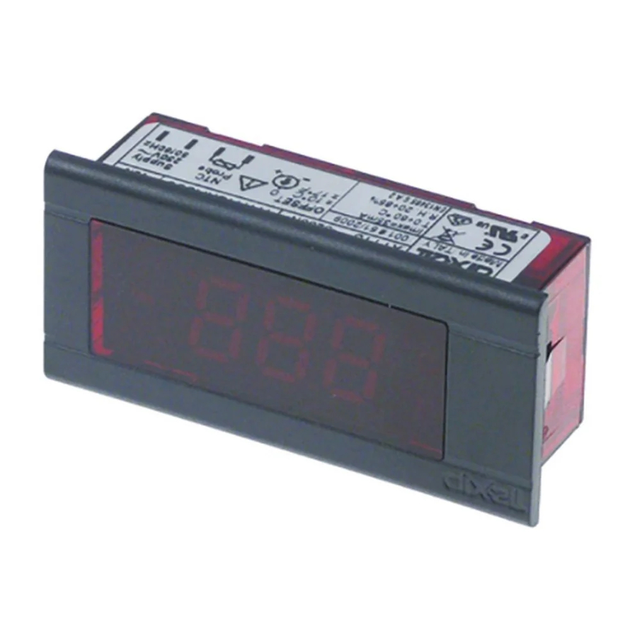
GENERAL DESCRIPTION
The XT11S is a new electronic digital thermometer which displays the current temperature and also logs the maximum and minimum temperatures experienced.
These max. / min. temperatures can be displayed at the touch of a button and reset if required.
INSTALLATION - 230V OR 115V VERSION (FIG.1)
The instrument is equipped with fast-on type spade terminals with probe connections separated from the power supply connections. To install the instrument proceed as follow:
Use insulated quick connector terminals for voltage and probe.

![warning]() Disconnect the power supply from the board by means of a panel switch, not supplied, (P1 in Fig.1).
Disconnect the power supply from the board by means of a panel switch, not supplied, (P1 in Fig.1). ![warning]() A Class II and certified according to IEC 60947-1 and 60947-3 approved panel switch has to be used.
A Class II and certified according to IEC 60947-1 and 60947-3 approved panel switch has to be used.![warning]() Fit the panel switch near the XT11S, in a place easy to reach, to make the power supply disconnection easy.
Fit the panel switch near the XT11S, in a place easy to reach, to make the power supply disconnection easy.- To protect the instrument against over current a 63mA external fuse has to be used.
DISPLAY OFFSET ADJUSTMENT
DISCONNECTION AND PROBE SUBSTITUTION (FIG.1)
![warning]() Disconnect the power supply on the board where the instrument is positioned, by means of the panel switch (P1 in Fig.1)
Disconnect the power supply on the board where the instrument is positioned, by means of the panel switch (P1 in Fig.1)
EXTERNAL PUSH-BUTTON CONNECTION (FIG.2)
In order to display the maximum and minimum values on the instrument, use the S1 Class II approved type push button, normally open. Button has to be rated for the maximum main supply voltage. (NOT SUPPLIED).
![warning]() Disconnect the power supply on the board where the instrument is positioned, by means of the panel switch (P1 in Fig.1)
Disconnect the power supply on the board where the instrument is positioned, by means of the panel switch (P1 in Fig.1)- Connect the push button in parallel with the probe as shown in Fig.2.

- For supply use double insulation cables, with at least 0.75 mm² as diameter (AWG minus or equal to 20).

DISPLAY OF MIN. AND MAX. TEMPERATURES LOGGED
Once the button for min & max temperatures has been connected, proceed as follows:
Maximum temperature display:
Minimum temperature display:
Probe offset value display:
Maximum/minimum temperature reset:
Power on and power failure warning:
When the power supply is turned on and after any power failure, when the max. and min. set values are visualised, the display flashes. This is to warn the user that there has been an interruption to the power supply.
To restore normal operation, follow the same procedure that is used for re-setting the maximum/minimum memory. (see Maximum /minimum temperature reset).
MAINTENANCE AND CLEANING
Instruments do not require particular maintenance. To clean frontal, just use a soft moist cloth and avoid using any strong detergent or solvent.
TECHNICAL DATA
Case: 64x31mm, depth: 19.5mm; self extinguishing polycarbonate.
Mounting: only for panel mounting; 25,5x59mm panel cut out (1.01x2.32inc.).
Frontal protection: IP20.
Electrical connections: fast-on type spade terminals with probe connections (2.8mm) separated from power supply connections (6.3mm).
Power supply: 230Vac ±10% 50/60Hz VDE approved or 110Vac ±10% 50/60Hz, or 12Vac/dc, or 24Vac/dc.
Absorbed current: 40mA.
Probe: NTC with double isolation for 230Vac or 110Vac version.
Display and measurement units: - 50.0÷99.9°C => 100 to110°C; -40÷230°F
NTC standard probe: -30÷105°C (-22÷220°F).
Display update delay times (optional) when the temperature increases: fixed at 1 or 3 minutes depending on model specified at time of order.
Operating temperature: T60°C/32÷140°F.
Storage temperature: -30÷75°C/-22÷167°F.
Relative humidity: 20÷85% (no condensing).
Maximum working height: 2000m a. s. l.
Installation category III; Transitory over-voltage: 4000V.
Pollution degree: 2 according to IEC 664.
Offset: ±10°C (±17°F).
Accuracy: from -30 to -10°C (-22÷14°F): 1°C (2°F) ±1 digit. from -10 to 110°C (14÷230°F): 0,5°C (1°F) ±1 digit.

Dixell S.r.l. - Z.I. Viadell'Industria, 27 - 32010 Pieve d'Alpago (BL) ITALY
Tel. +39.0437.9833 r.a. - Fax +39.0437.989313 - EmersonClimate.com/Dixell - [email protected]


Documents / ResourcesDownload manual
Here you can download full pdf version of manual, it may contain additional safety instructions, warranty information, FCC rules, etc.
Thank you! Your question has been received!
Need Assistance?
Do you have a question about the Dixell XT11S that isn't answered in the manual? Leave your question here.