Table of Contents
Quick Links
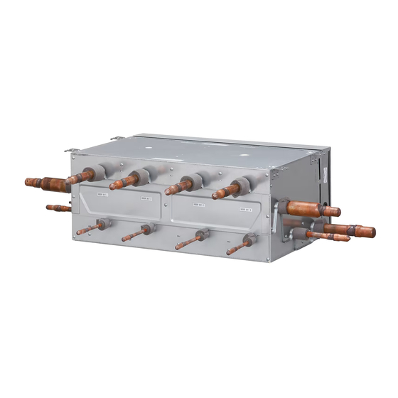
UTP-RX04BH
TM
INSTALLATION MANUAL
INSTALLATIONSANLEITUNG
KÄLTEMITTEL-ABZWEIGUNGS-GERÄT
MANUEL D'INSTALLATION
UNITÉ DE DÉRIVATION DE RÉFRIGÉRANT
MANUAL DE INSTALACIÓN
UNIDAD DE DERIVACIÓN DE REFRIGERANTE
Únicamente para personal de servicio autorizado.
MANUALE DI INSTALLAZIONE
UNITÀ REFRIGERANTE SECONDARIA
A uso esclusivo del personale tecnico autorizzato.
ΕΓΧΕΙΡΙΔΙΟ ΕΓΚΑΤΑΣΤΑΣΗΣ
ΜΟΝΆΔΑ ΔΙΑΚΛΆΔΩΣΗΣ ΨΥΚΤΙΚΟΎ
Μόνο για εξουσιοδοτημένο τεχνικό προσωπικό.
MANUAL DE INSTALAÇÃO
UNIDADE DE DERIVAÇÃO DE REFRIGERANTE
РУКОВОДСТВО ПО УСТАНОВКЕ
Только для авторизованного обслуживающего персонала.
For authorized service personnel only.
Nur für autorisiertes Fachpersonal.
Pour le personnel agréé uniquement.
Apenas para técnicos autorizados.
МОДУЛЬ ВЕТКИ ОХЛАЖДЕНИЯ
MONTAJ KILAVUZU
SOĞUTUCU DAĞITIM ÜNITESI
Yalnızca yetkili servis personeli için.
PART NO. 9366247043-02
RB UNIT
Table of Contents

Related Manuals for Fujitsu AIRSTAGE UTP-RX04BH


Summary of Contents for Fujitsu AIRSTAGE UTP-RX04BH
- Page 1 INSTALLATION MANUAL RB UNIT For authorized service personnel only. INSTALLATIONSANLEITUNG KÄLTEMITTEL-ABZWEIGUNGS-GERÄT Nur für autorisiertes Fachpersonal. MANUEL D’INSTALLATION UNITÉ DE DÉRIVATION DE RÉFRIGÉRANT Pour le personnel agréé uniquement. MANUAL DE INSTALACIÓN UTP-RX04BH UNIDAD DE DERIVACIÓN DE REFRIGERANTE Únicamente para personal de servicio autorizado. MANUALE DI INSTALLAZIONE UNITÀ...
-
Page 2: Table Of Contents
INSTALLATION MANUAL This mark indicates procedures which, if improperly per- CAUTION formed, might possibly result in personal harm to the user, or PART NO. 9366247043-02 damage to property. VRF system RB unit Read carefully all security information before use or install the air conditioner. CONTENTS Do not attempt to install the air conditioner or a part of the air conditioner by yourself. -
Page 3: Accessories
Table 1) Connection specifi cations 2.3. Accessories Maximum capacity of 1 RB unit Do not discard the accessories required for installation until the installation work is connectable indoor Q ≤ 56.0kW complete. units (Q) 2 RB units (in serial) *1 Name and shape Q’ty Application... -
Page 4: Installation Dimensions
CAUTION Install this unit, power supply cable and transmission cable at least 1 m away from a television or radio receivers. The purpose of this is to prevent TV reception interference or radio noise. (Even if they are installed more than 1 m apart, you could still receive noise under some signal conditions.) If children under 10 years old may approach the unit, take preventive measures so that they cannot reach the unit. -
Page 5: Pipe Installation
Type B) If connecting 2 or more indoor units downstream of the RB unit CAUTION Select the connection pipe from Table 1, based on the Be sure to provide adequate maintenance space when installing the unit above the total capacity of indoor units connected downstream. ceiling. -
Page 6: Selecting The Pipe Material
(3) Indoor unit model codes and model selection capacity 6.4. Installing heat insulation Model code Indoor unit CAUTION 11.2 capacity (Kw) Insulate the suction gas pipe, discharge gas pipe, liquid pipe, and gas pipe with heat insulation. Model code Use heat insulation with heat resistance above 120 °C. In addition, if the humidity level at the installation location of the refrigerant piping is Indoor unit 12.5... -
Page 7: Electrical Requirement
(3) Use the specifi ed cables, connect them securely, and fasten them so that there is Do not connect power supply cables to the transmission terminals, as this will no stress placed on the terminals. damage the product. (4) Use an appropriate screwdriver to tighten the terminal screws. Never bundle the power supply cable and transmission cable, together. - Page 8 7.3.3 Wiring method The wiring example for RB units ,outdoor units and indoor units is shown in the fi gure. *1:Cooling only Outdoor unit Transmission Transmission Refrigerant piping Indoor unit RB unit RB unit RB unit [UTP-RX01*H] Power Power Power supply supply supply...
- Page 9 7.3.4. Work procedure Detail A : Power supply cable (1) Remove the control box cover. (3 screws) Earth (ground) Detail B : Transmission cable Earth (ground) To outdoor unit / other RB unit / indoor unit (Cooling only) (2) Connect the transmission cable to the transmission cable terminal. (3) Firmly attach the transmission cables using the accessory cable ties.
-
Page 10: Field Setting
8. FIELD SETTING 9. EXTERNAL INPUT CAUTION ● RB unit can be switched cooling priority and heating priority by using RB unit PC board CNA01 or CNA02. Use an insulated screwdriver to set the dip switches. ● The "external input priority mode" must be set by changing DIP switch SET2-1,2 on PC board of RB unit. -
Page 11: Test Run
When connected to Apply voltage terminals of multiple RB units with a connected 12. INDICATOR LAMP STATUS unit, be sure to make a branch outside the RB unit using a pull box, etc. as shown on below example. Power indica- Error DC power sup- tor lamp...