Hitachi HIDIC EH-150 Applications Manual
1 axis pulse positioning control module
Hide thumbs
Also See for HIDIC EH-150:
- Applications manual (117 pages) ,
- Instruction manual (29 pages) ,
- Applications manual (114 pages)

Related Manuals for Hitachi HIDIC EH-150


Summary of Contents for Hitachi HIDIC EH-150
- Page 1 HITACHI PROGRAMMABLE CONTROLLER 1 Axis Pulse Positioning Control Module EH-POS APPLICATION MANUAL NJI-315(x)
- Page 2 Personnel who are to install and operate the equipment should carefully study this manual and any other referred to by it prior to installation and/or operation of the equipment. Hitachi Industrial Equipment Systems Co., Ltd. constantly strives to improve its products, and the equipment and the manual(s) that describe it may be different from those already in your possession.
- Page 3 Hitachi neither assumes, nor authorizes any other person to assume for Hitachi, any other liability in connection with the sale of this PLC.
- Page 4 Since Hitachi does not possess full access to data concerning all of the uses and applications of customer’s products, responsibility is assumed by Hitachi neither for customer product design nor for any infringement of patents or rights of others, which may result from Hitachi assistance.
- Page 5 Safety Precautions Read this manual and related documents thoroughly before installing, operating, performing preventive maintenance or performing inspection, and be sure to use the unit correctly. Use this product after acquiring adequate knowledge of the unit, all safety information, and all cautionary information. Also, make sure this manual enters the possession of the chief person in charge of safety maintenance.
- Page 6 2. About wiring REQUIRED Always perform grounding (FE terminal). If grounding is not performed, there is a risk of electric shocks and malfunctions. CAUTION Connect power supply that meets rating. If a power supply that does not meet rating is connected, fire may be caused. The wiring operation should be performed by a qualified personnel.
- Page 7 4. About preventive maintenance DANGER Do not connect the of the battery in reverse. Also, do not charge, disassemble, heat, place in fire, or short circuit the battery. There is a risk of explosion or fire. PROHIBITED Do not disassemble or modify the unit. These actions may result in fire, malfunction, or malfunction.
- Page 8 Table of contents Chapter 1 Introduction 1-1 to 1-3 Before Use................................1-1 Accessaries...............................1-2 Option................................1-3 Chapter 2 Features Chapter3 System configuration 3-1 to 3-2 Structure and Parts name..........................3-1 System configuration.............................3-2 Chapter 4 Function and Performance Specifications 4-1 to 4-7 General Specifications...........................4-1 Functional Specifications ..........................4-2 I/O Interface Specifications...........................4-3 Input/output Signal............................4-5 Output Method..............................4-6...
- Page 9 9.3.2 Caution of Input / output wiring....................9-3 Example of wiring with a Servo Amplifier....................9-4 9.4.1 Example of wiring with Hitachi AD series (increment) ............9-4 9.4.2 Example of wiring with Hitachi AD series (absolute)..............9-5 9.4.3 Example of wiring with Yasukawa Σ...
- Page 10 14.2 Installtion of Positioner ..........................14-2 14.3 Function................................14-3 14.3.1 Mode selection...........................14-4 14.3.2 Monitor mode ............................14-5 14.3.3 Set mode.............................14-6 14.3.4 Run mode............................14-10 Chapter 15 Appendix 15-1 to 15-6 15.1 Data Setting Sheet ( Common Parameter ) .....................15-1 15.2 Data Setting Sheet ( Automatic Operation Positional data )..............15-2 15.3 Cable for I/O connector(Option)......................15-3 15.4 For using on the side of EH-IOCP .......................15-4 Glossary................................15-5...
- Page 11 Capture 1 Introduction Chapter 1 Introduction Before use This instruction manual describes how properly operate the EH-POS (Positioning Control Module), which is one of the special function module of EH-150 Programmable Logic controller (PLC). Carefully read this manual to familiarize yourself with the procedures respectively of installation, operation, and maintenance and inspection.
- Page 12 Capture 1 Introduction Accessories The following accessories are packed in the EH-POS module. Check each item after unpacking the module. Number Item name Model Appearance Remark of pieces 1-axis positioning EH-POS Caution module Use EH-CPU308 or EH- CPU316 for CPU module with EH-POS.
- Page 13 EH-POC10 (1m) Supplied by Sumotomo 3M. Cable for I/O connector Plug:20 pole 10120-6000EL EH-POC20 (2m) Case: 10320-3210-000 EH-POC50 (5m) (1)HITACHI AD series Cable for servo amp (2)YASUKAWA Σ series (3)SANYO P series Soon on sale Caution Contact sales office detailed information.
- Page 14 ABS (absolute value) encoder input EH-POS applies for ABS (absolute value) encoder input. At setting of “Homing mode” in common parameter, you can set homing mode of absolute encoder. (Applied manufacturer/series : Hitachi AD series,YasukawaΣseries/Σ series, Sanyo Electric P series) Battery-less EH-POS applies EEPROM as memory and realizes to back-up memory without battery.
- Page 15 Chapter 3 System configuration Chapter 3 System configuration Structure and Parts name EH-POS Name and function Model Approx. 0.18 kg Weight 1) Lock button Dimension(mm) 2) Reset switch 3)Connector for Positioner 4) I/O connector 5) DIP switch Name Function Remarks Lock button This is used when removing the module from the base unit.
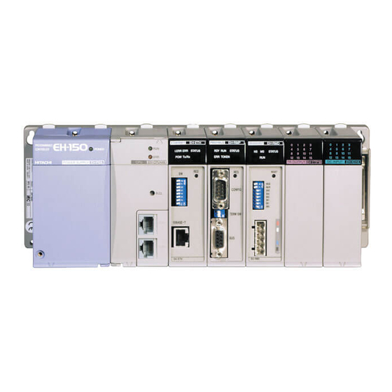
- Page 16 Chapter 3 System configuration System configuration The system configuration of the EH-150 is shown below. The EH-150 is a module-type programmable controller with the configuration shown in Figure 3.1. 3 ) P o s i t i o n i n g m o d u l e , 1) P o w e r m o d u l e I / O m o d u l e 4 ) B a s i c b a s e...
- Page 17 Chapter 4 Function and Performance Specifications Chapter 4 Function and Performance Specifications General Specifications The general specifications of EH-POS are shown in the table below. Item Specification Power requirement 5 V DC, 300 mA, 600 mA (when Positioner connected ) , (supplied from the programmable controller) 0 to 55 °C storing temperature –10 to 75 °C) Operating temperature...
- Page 18 1. Desirable homing 2. Low speed homing 3. High speed homing (Limit SW OFF edge) 4. High speed homing (Z or C Pulse input) AD series of HITACHI, Σ/Σ Absolute encoder of YASUKAWA and P series of SANYO are available.
- Page 19 Chapter 4 Function and Performance Specifications I/O Interface Specifications I/O interface specifications of EH-POS are shown in the table below. Items Specification CW/CCW Pulse line Output Opto-isolated open collector transistor (max.30 V DC, Output CK/Sign Pulse line Output 30 mA Resistor Load) Opto-isolated line driver output (5 V DC) 100 µA or less Max.
- Page 20 Chapter 4 Function and Performance Specifications 1) Positioner connector (CN1): Base on RS-422 Terminal configuration Diagram of internal circuit Sign signal name Do− Driver output − Internal circuit Driver output + C N 1 Receiver input − Ri− -12V Receiver input + 5 V DC+ 12 V DC−...