
Related Manuals for Asus Aaeon BOXER-8641AI


Summary of Contents for Asus Aaeon BOXER-8641AI
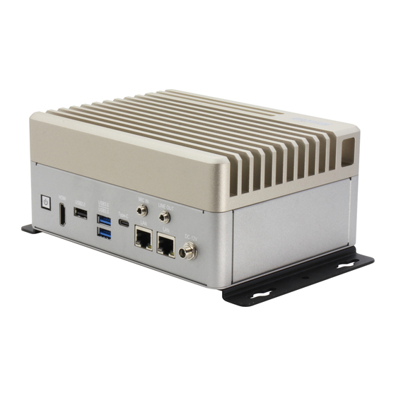
- Page 1 BOXER-8641AI AI@Edge Compact Fanless Embedded AI System with NVIDIA® AGX Orin™ User’s Manual 1 Last Updated: November 4, 2022...
- Page 2 Copyright Notice This document is copyrighted, 2022. All rights are reserved. The original manufacturer reserves the right to make improvements to the products described in this manual at any time without notice. No part of this manual may be reproduced, copied, translated, or transmitted in any form or by any means without the prior written permission of the original manufacturer.
- Page 3 Acknowledgements All other products’ name or trademarks are properties of their respective owners. NVIDIA®, the NVIDIA logo, Jetson™, Jetson Orin™, and JetPack™ are ⚫ trademarks of the NVIDIA Corporation. Arm® and Arm®v8-M architecture are registered trademarks of Arm Limited. ⚫ Linux®...
- Page 4 Packing List Before setting up your product, please make sure the following items have been shipped: Item Quantity BOXER-8641AI ⚫ Wallmount Bracket ⚫ Screw Package ⚫ Power Adapter Optional ⚫ If any of these items are missing or damaged, please contact your distributor or sales representative immediately.
- Page 5 About this Document This User’s Manual contains all the essential information, such as detailed descriptions and explanations on the product’s hardware and software features (if any), its specifications, dimensions, jumper/connector settings/definitions, and driver installation instructions (if any), to facilitate users in setting up their product. Users may refer to the product page at AAEON.com for the latest version of this document.
- Page 6 Safety Precautions Please read the following safety instructions carefully. It is advised that you keep this manual for future references All cautions and warnings on the device should be noted. All cables and adapters supplied by AAEON are certified and in accordance with the material safety laws and regulations of the country of sale.
- Page 7 As most electronic components are sensitive to static electrical charge, be sure to ground yourself to prevent static charge when installing the internal components. Use a grounding wrist strap and contain all electronic components in any static-shielded containers. If any of the following situations arises, please the contact our service personnel: Damaged power cord or plug Liquid intrusion to the device iii.
- Page 8 FCC Statement This device complies with Part 15 FCC Rules. Operation is subject to the following two conditions: (1) this device may not cause harmful interference, and (2) this device must accept any interference received including interference that may cause undesired operation.
- Page 9 China RoHS Requirements (CN) 产品中有毒有害物质或元素名称及含量 AAEON System QO4-381 Rev.A0 有毒有害物质或元素 部件名称 铅 汞 镉 六价铬 多溴联苯 多溴二苯 醚(PBDE) (Pb) (Hg) (Cd) (Cr(VI)) (PBB) 印刷电路板 × ○ ○ ○ ○ ○ 及其电子组件 外部信号 × ○ ○ ○ ○ ○ 连接器及线材 外壳 ○...
- Page 10 China RoHS Requirement (EN) Hazardous and Toxic Materials List AAEON System QO4-381 Rev.A0 Hazardous or Toxic Materials or Elements Component Name PCB and Components Wires & Connectors for Ext.Connections Chassis CPU & RAM HDD Drive LCD Module Optical Drive Touch Control Module Battery This form is prepared in compliance with the provisions of SJ/T 11364.
-
Page 11: Table Of Contents
Table of Contents Chapter 1 - Product Specifications..................1 Specifications ......................2 Chapter 2 – Hardware Information ..................5 Dimensions ....................... 6 Jumpers and connectors..................7 List of Jumpers ......................8 2.3.1 Setting Jumpers ..................8 2.3.2 M.2 SATA/PCIe Mode (JP1) ..............9 2.3.3 Auto Power Mode (JP2) ................. - Page 12 2.4.15 M.2 2280 M-Key Connector (SATA or NVM) (CN14) ...... 25 2.4.16 SATA Connector (CN28) ............... 26 2.4.17 DIO Port Connector (CN30) ..............27 2.4.18 Micro USB Connector (Flash OS) (CN34) ......... 28 2.4.19 M.2 3052 B-Key (USB3+PCIe) Connector (CN6) ......29 Hardware Assembly ....................
-
Page 13: Chapter 1 - Product Specifications
Chapter 1 Chapter 1 - Product Specifications... -
Page 14: Specifications
Specifications System AI Accelerator NVIDIA® Jetson AGX Orin™ 8-core ARM v8.2 64-bit CPU, 2MB L2 + 4MB L3 System Memory 32GB 256-bit LPDDR5 (205GB/s) Storage Device 64GB eMMC 5.1 x 1 MicroSD Slot x 1 SATA Drive Bay x 1 Display Interface HDMI 2.0 x 1 Ethernet... - Page 15 System Expansion M.2 2230 E-Key x 1 (for Wi-Fi/BT) M.2 3052 B-Key x 1 M.2 2280 M-Key (for NVMe) x 1 2.5” SATA Port Drive x 1 SIM Slot x 1 Indicator Power LED x 1 OS Support Linux (NVIDIA Jetpack™ 5.0 or above) Power Supply Power Requirement 12V DC with lockable DC Jack...
- Page 16 Environmental Anti-Shock 50G peak acceleration (11 msec. duration: eMMC, microSD, or SSD) Certification CE / FCC Class B Chapter 1 – Product Specifications...
-
Page 17: Chapter 2 - Hardware Information
Chapter 2 Chapter 2 – Hardware Information... -
Page 18: Dimensions
Dimensions Chapter 2 – Hardware Information... -
Page 19: Jumpers And Connectors
Jumpers and connectors Chapter 2 – Hardware Information... -
Page 20: List Of Jumpers
List of Jumpers The board has a number of jumpers that allow you to configure your system to suit your application. The table below shows the function of each of the board's jumpers Label Function M.2 SATA/PCIe mode select AT/ATX mode select FAN Voltage select AGX Orin/Xavier select 2.3.1... -
Page 21: Sata/Pcie Mode (Jp1)
2.3.2 M.2 SATA/PCIe Mode (JP1) Function SATA PCIe (Default) 2.3.3 Auto Power Mode (JP2) Function 1-2 Open ATX (Default) 1-2 Closed 2.3.4 FAN Voltage Mode (JP3) Function +5V (Default) +12V 2.3.5 AGX Orin RTC Mode (Default) (JP4) Function 2-4, 4-6 AGX Xavier Chapter 2 –... -
Page 22: List Of Connectors
List of Connectors The board has a number of connectors that allow you to configure your system to suit your application. The table below shows the function of each of the board's connectors Label Function RTC Battery Connector HDMI Connector Giga LAN Connector M.2 B-Key (USB3.0+PCIe) Connector SIM Card... - Page 23 Label Function CN34 Micro USB for Flash OS Recovery Switch Reset Switch Power On/Off Switch Chapter 2 – Hardware Information...
-
Page 24: Rtc Connector (Cn1)
2.4.1 RTC Connector (CN1) Signal Signal 2.4.2 HDMI Connector (CN3) Signal Signal HDMI_DATA2_P HDMI_DATA2_N HDMI_DATA1_P HDMI_DATA1_N HDMI_DATA0_P HDMI_DATA0_N HDMI_CLK_P HDMI_CLK_N Chapter 2 – Hardware Information... -
Page 25: Dual Usb 3.2 Type-A Connector (Cn33)
Signal Signal HDMI_SCL HDMI_SDA HDMI_PWR HDMI_HDP 2.4.3 Dual USB 3.2 Type-A Connector (CN33) Signal Signal VBUS_1 VBUS_2 (A)D- (B)D- (A)D+ (B)D+ (A)SSRX- (B)SSRX- (A)SSRX+ (B)SSRX+ (A)SSTX- (B)SSTX- (A)SSTX+ (B)SSTX+ Chapter 2 – Hardware Information... -
Page 26: Power-In Connector (Cn25)
2.4.4 Power-In Connector (CN25) Signal Signal PWR_IN 2.4.5 Giga LAN Connector (CN4/CN31) Signal Signal MDI0+ MDI0- MDI1+ MDI1- MDI2+ MDI2- MDI3+ MDI3- Chapter 2 – Hardware Information... -
Page 27: Com Port Connector (/Dev/Ttyths1) (Cn9, Sw2)
2.4.6 COM Port Connector (/dev/ttyTHS1) (CN9, SW2) RS-232 RS-422 RS-485 TXD- TXD- RXD+ TXD+ TXD+ RXD- Chapter 2 – Hardware Information... - Page 28 RS-232 RS-422 RS-485 Chapter 2 – Hardware Information...
-
Page 29: Com Port Connector (/Dev/Ttyths4) (Cn8, Sw1)
2.4.7 COM Port Connector (/dev/ttyTHS4) (CN8, SW1) RS-232 RS-422 RS-485 TXD- TXD- RXD+ TXD+ TXD+ RXD- Chapter 2 – Hardware Information... - Page 30 RS-232 RS-422 RS-485 Chapter 2 – Hardware Information...
-
Page 31: Rs-232/422/485 Select (Sw1, Sw2)
2.4.8 RS-232/422/485 Select (SW1, SW2) Mode 1T/1R RS-232 1T/1R RS-422 1T/1R RS-485 Low power shutdown Enable RS-422/RS-485 bias and termination resistors. Disable RS-422/RS-485 bias and termination resistors. 250kbps for RS-232 and RS-485/RS-422 RS-232 to 3Mbps and RS-485/RS-422 to 20Mbps 2.4.9 UART Debug Port Connector (CN22) Signal VCC 3.3V... -
Page 32: Front Panel Connector (Cn18)
2.4.10 Front Panel Connector (CN18) Signal Signal Carrier board standby Button power CVM_PRSNT1 System Overcurrent indicator LED Green LED Blue LED Power (105ohm Pu) Chapter 2 – Hardware Information... -
Page 33: Usb 3.0 Type-C Connector (Cn32)
2.4.11 USB 3.0 Type-C Connector (CN32) Signal Signal (A)SSTX+ (B)SSRX+ (A)SSTX- (B)SSRX- VBUS_1 VBUS_2 SBU2 (A)D+ (B)D- (A)D- (B)D+ SBU1 VBUS_1 VBUS_2 (A)SSRX- (B)SSTX- (A)SSRX+ (B)SSTX+ Chapter 2 – Hardware Information... -
Page 34: Microsd Connector (Cn17)
2.4.12 MicroSD Connector (CN17) uSD Card Pin Map Pin No (Card) Pin No (Connector) Function DAT2 CD/DAT3 DAT0 DAT1 Chapter 2 – Hardware Information... -
Page 35: Audio Connector (Cn12)
2.4.13 Audio Connector (CN12) Signal Signal MIC1 MIC2 GPIO4 HPO_R MIC_IN_DET HPO_L GPIO3 GPIO3: Headphone or jack detection. GPIO4: Presence – detects if audio dongle is connected to header. Chapter 2 – Hardware Information... -
Page 36: 2230 E-Key Connector (Cn13)
2.4.14 (CN13) M.2 2230 E-Key Connector Chapter 2 – Hardware Information... -
Page 37: 2280 M-Key Connector (Sata Or Nvm) (Cn14)
2.4.15 (CN14) M.2 2280 M-Key Connector (SATA or NVM) Chapter 2 – Hardware Information... -
Page 38: Sata Connector (Cn28)
2.4.16 SATA Connector (CN28) Signal Chapter 2 – Hardware Information... -
Page 39: Dio Port Connector (Cn30)
2.4.17 DIO Port Connector (CN30) Function Voltage Level GPIO493 3.3V- GPIO492 3.3V- GPIO491 3.3V- GPIO494 3.3V- GPIO495 3.3V- GPIO422 3.3V- GPIO393 3.3V- GPIO344 3.3V- Chapter 2 – Hardware Information... -
Page 40: Micro Usb Connector (Flash Os) (Cn34)
Function Voltage Level GPIO493 3.3V- GPIO491 3.3V- GPIO495 3.3V- GPIO393 3.3V- 3.3V- GPIO492 3.3V- GPIO494 3.3V- GPIO422 3.3V- GPIO344 2.4.18 Micro USB Connector (Flash OS) (CN34) Signal Signal USB1- USB1+ Chapter 2 – Hardware Information... -
Page 41: 3052 B-Key (Usb3+Pcie) Connector (Cn6)
2.4.19 M.2 3052 B-Key (USB3+PCIe) Connector (CN6) Chapter 2 – Hardware Information... -
Page 42: Hardware Assembly
Hardware Assembly This section details the steps needed to install various hardware components for the BOXER-8641AI. 2.5.1 M.2 Expansion Module Installation The M.2 2280 M-Key, M.2 2230 E-Key, and M.2 3052 B-Key slots can be accessed via removable covers on the bottom panel of the BOXER 8641AI system as shown in the following diagram. -
Page 43: 2.5" Hdd Or Ssd Installation
2.5.2 2.5” HDD or SSD Installation The 2.5” HDD or SSD drive bay can accessed for drive installation via removable covers on the bottom panel of the BOXER 8641AI system as shown in the following diagram. Chapter 2 – Hardware Information... -
Page 44: Wall Mount Installation
2.5.3 Wall Mount Installation The BOXER 8641AI can be secured via a wall mount as shown in the following diagram. Chapter 2 – Hardware Information... -
Page 45: Chapter 3 - Bsp Flash Guide
Chapter 3 Chapter 3 – BSP Flash Guide... -
Page 46: Before Installation
Before Installation Before starting the process make sure your BOXER-8641AI system is turned off and the power is disconnected. You will need a Host PC running Ubuntu 18.04, and make sure the NVIDIA Jetson Orin AGX module is installed onto the BOXER-8641AI carrier board system. -
Page 47: Connecting To Pc/ Force Recovery Mode
Connecting to PC/ Force Recovery Mode Step 1: On the Host computer, open Linux terminal and enter the following command to extract the compressed BSP image files (BSP file name may vary): $ sudo tar -zxvf Internal.tar.gz Note: Do not decompress the file (Internal.tar.gz) using a Windows OS, BSP should only be decompressed in a Linux EXT3/4 file system. - Page 48 Note: Recovery mode cannot be initiated if the NVIDIA Jetson Orin AGX module is disassembled. Ensure the NVIDIA Jetson Orin AGX module is installed and refer to the image below to perform the steps: Chapter 3 – BSP Flash Guide...
-
Page 49: Flash Image To Board
Flash Image to Board Use the following steps to flash the OS to the BOXER-8641AI. Open terminal on the Ubuntu Host PC, then access the folder you extracted in the previous section. Enter the following command in terminal to flash the image: $ sudo ./flashboxer.sh Wait as the image is installed. -
Page 50: Check Bsp Version
Check BSP Version Once the flash image is successfully installed, the BOXER-8641AI will reboot automatically, then check the BSP version to see if the system is flashing the correct version of BSP . Open a Terminal, and type command “cat /proc/product” The version name will follow the format of: {PJ_IF}. -
Page 51: Chapter 4 - Os User Guide
Chapter 4 Chapter 4 – OS User Guide... -
Page 52: Introduction
Introduction The BOXER-8641AI’s OS, Ubuntu/Linux version, and preinstalled SDK components are as follows: Jetpack 5.0.2 (l4t 35.1) Ubuntu/Linux version: Ubuntu version: 20.04.4 Kernel version: 5.10.104-tegra UEFI version: EFI v2.70 by EDK II Built-in Jetson SDK Components: CUDA Toolkit for L4T 11.4 cuDNN 8.4 TensorRT 8.4 OpenCV 4.5... -
Page 53: Update Note
Update Note Running $ sudo apt upgrade command in terminal will overwrite the Aaeon kernel device tree(.dtb)/kernel image(Image)/bootloader in the OS, which can lead to unexpected results, including the loss of I/O ports. So Aaeon default disable Nvidia apt Repo for updating Nvidia apt package. -
Page 54: Boxer-8641Ai Power Mode
BOXER-8641AI Power Mode NVIDIA Jetson Orin AGX power mode can be selected and monitored by GUI, please refer to the following picture: Chapter 4 – OS User Guide...