Quick Links
Installation Guide
Pressure Monitoring
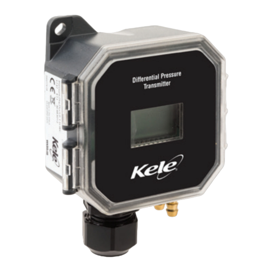
Differential Pressure / Air Velocity Transducer
Product Overview
KDP2M
The KDP2M transducer can measure either air pressure or velocity with the flip of a
Patent Pending
switch. The KDP2M is available in three installation configurations: duct, panel or
50
universal. Duct and panel models have two pressure and velocity options: 0-1 in. WC /
0-3,000 ft/min or 1-10 in. WC / 3,000-6,000 ft/min with four field-selectable sub-ranges.
NOTICE
The universal model comes in one pressure/velocity range: 0-10 in. WC / 0-6,000 ft/
• This product is not intended for life or
safety applications.
min with seven field-selectable sub-ranges. All variants are available with and without
• Do not install this product in hazardous
display. The KDP2M has an IP65/NEMA 4 environmental rating and a 5-year limited
or classi ed locations.
warranty.
• Read and understand the instructions
before installing this product.
• Turn o all power supplying equipment
Product Identification
before working on it.
• The installer is responsible for
Enclosure
conformance to all applicable codes.
-
KDP2M
If this product is used in a manner not speci ed
D = Duct
by the manufacturer, the protection provided
P = Panel
by the product may be impaired. No
responsibility is assumed by the manufacturer
for any consequences arising out of the use of
this material.
Range
KDP2MU
-
010 = Pressure: 0 to 10 in. WC / 0 to 2,500 Pa
Dimensions
in. (mm)
3.5
(88)
3.5
(88)
Z207542-0B
Page 1 of 8
© 2018 Kele / USA 888-397-5363 / [email protected]
Installation Guide
Pressure Monitoring
Installation, Wiring
1. Plan the installation. Panel or duct mount?
& Configuration
Static Pressure
Panel Installations
Duct Installations
Velocity with FXP Probe
For velocity applications, use the FXP Series air velocity/measurement probe or AA18,
AA19 or AA20 velocity pitot tubes. For use with the PX3P (panel) and PX3U (universal)
models in Velocity mode only. Sold separately.
2. For duct mount applications, thread the probe into the back of the device housing, as
shown in the dimensional drawing.
3. Configure the internal tubing for the selected installation method as described below.
Duct mount tubing configuration:
a. Connect the right-side tube to the rear brass barb marked as "-" on the
underside of the device housing.
b. Connect the left-side tube to the probe in the back of the device housing.
Panel mount tubing configuration:
a. Connect the right-side tube to the rear brass barb marked as "-" on the
underside of the device housing.
b. Connect the left-side tube to the front brass barb marked as "+" on the
underside of the device housing.
Tubing for Duct Mount
Tubing for Duct Mount
Z207542-0B
Page 3 of 8
© 2018 Kele / USA 888-397-5363 / [email protected]
KDP2M Series
Range
Local Display
-
1 = Pressure: 0 to 1 in. WC / 0 to 250 Pa
LCD = LCD Display
Velocity: 0 to 3,000 ft/min / 0 to 15 m/s
X = No Display
10 = Pressure: 1 to 10 in. WC/250 to 2,500 Pa
Velocity: 0 to 6,000 ft/min / 0 to 30 m/s
Local Display
-
-
LCD = LCD Display
X = No Display
Velocity: 0 to 7,000 ft/min / 0 to 35 m/s
1.6
(42)
3.1
(78)
4.4
(112)
7.4
(188)
1.6
(42)
Differential Pressure
FILTER
Velocity with AA18/AA19/AA20 Pitot Tube
Tubing for Panel Mount
Tubing for Panel Mount
Installation Guide
Pressure Monitoring
®
Specifications
Media Compatibility Dry air or inert gas
Input Power Three-wire Volt mode: 24 Vac or 12-30 Vdc*
Output Power Field-selectable: 2-wire, loop-powered 4-20 mA
Pressure
Range 1
Pressure
Range 10
Pressure
NIST
Range 010
-
N = NIST
X = None
Response Time Standard: T95 in 20 sec, Fast: T95 in 2 sec, DIP switch selectable
NIST
Display (Option) Pressure mode: Signed 3-1/2 digit LCD, indicates pressure, overrange indicator
Proof Pressure 3 psid (20, 600 Pa)
N = NIST
X = None
Burst Pressure 5 psid (34, 500 Pa)
Pressure Mode Accuracy ±1% FS (combined linearity and hysteresis)
Velocity Mode Accuracy ±90 ft/min (±0.45 m/s) plus 5% of measured value**
Temperature Effect 1" (250 Pa) models: 0.05%/°C; 10" (2,500 Pa) models: 0.01%/°C
Zero Drift (1-year) 1" (250 Pa) models: 2.0% max.; 10" (2,500 Pa) models: 0.5% max.
Zero Adjust Pushbutton auto-zero and digital input (2-position terminal block)
Operating Environment 0 to 60 °C (32 to 140 °F)
Altitude of Operation 0 to 3,000 m
Pollution Degree 2
Humidity Range 100% RH, non-condensing
Mounting Location For indoor use only.
Suggested Cable Shielded:
0.3
(7)
Environmental Rating IP65, NEMA 4
Flammability Rating UL 94 5VA fire retardant ABS, plenum rated
Limited Warranty 5 years
EMC Conformance: EN 61000-6-3 and A1 Class B, EN 61000-6-1. * Class 2/II power source. ** For measured values between 200 and 7000 ft/min (1 and 35 m/s).
0818
Z207542-0B
Page 2 of 8
Installation Guide
Pressure Monitoring
®
Installation, Wiring
& Configuration (cont.)
0818
Z207542-0B
Page 4 of 8
Two-wire mA mode: 12-30 Vdc*
Minimum input voltage for 4 to 20 mA operation: 250 Ω loop = 12 Vdc; 500 Ω loop = 19 Vdc
(DC only, clipped and capped), 24 Vac/dc or 3-wire 0-5V/0-10V
Minimum load resistance for Volt operation: 5 kΩ
Pressure
Unidirectional: 0.1/0.25/0.5/1 in. WC FS, switch selectable
Mode
Bidirectional: ±0.1/±0.25/±0.5/±1 in. WC FS, switch selectable
Unidirectional: 25/50/100/250 Pa FS, switch selectable
Bidirectional: ±25/±50/±100/±250 Pa FS, switch selectable
Velocity
500/1,000/2,000/3,000 ft/min
Mode
2.5/5/10/15 m/s
Pressure
Unidirectional: 1.0/2.5/5/10 in. WC FS, switch selectable
Mode
Bidirectional: ±1.0/±2.5/±5/±10 in. WC FS, switch selectable
Unidirectional: 250/500/1,000/2500 Pa FS, switch selectable
Bidirectional: ±250/±500/±1,000/±2500 Pa FS, switch selectable
Velocity
3,000/4,000/5,000/6,000 ft/min
Mode
15/20/25/30 m/s
Pressure
Unidirectional: 0.1/0.25/0.5/1/2.5/5/10 in. WC FS, switch selectable
Mode
Bidirectional: ±0.1/±0.25/±0.5/±1/±2.5/±5/±10 in. WC FS, switch selectable
Unidirectional: 25/50/100/250/500/1,000/2500 Pa FS, switch selectable
Bidirectional: ±25/±50/±100/±250/±500/±1,000/±2500 Pa FS, switch selectable
Velocity
500/1,000/2,000/3,000/4,000/5,000/6,000/7,000 ft/min
Mode
2.5/5/10/15/20/25/30/35 m/s
Mode Unidirectional or bidirectional, DIP switch selectable
Velocity mode: Signed 4-1/2 digit LCD, indicates velocity, overrange indicator
(Relative to 25 °C) 0 to 50 °C (32 to 122 °F)
Fittings Brass barb; 0.24" (6.1 mm) o.d.
Belden #9939 (22 AWG) 3-wire multi-conductor (or similar)
Belden #9940 (22 AWG) 4-wire multi-conductor (or similar)
Belden #9939 (22 AWG) 5-wire multi-conductor (or similar)
Unshielded:
Belden #8443 (22 AWG) 3-wire multi-conductor (or similar)
Belden #8444 (22 AWG) 4-wire multi-conductor (or similar)
Belden #8445 (22 AWG) 5-wire multi-conductor (or similar)
© 2018 Kele / USA 888-397-5363 / [email protected]
4. Mount the transducer (see the screw hole diagram below).
in. (mm)
3.3
(83)
CTR-CTR
5.
For applications using conduit, remove the cable gland nut on the bottom of the unit.
Thread a standard 1/2-inch NPT female threaded coupler onto the body of the cable
gland. Connect the opposite end of the coupler to the conduit.
© 2018 Kele / USA 888-397-5363 / [email protected]
®
0818
®
2.3
(59)
CTR-CTR
2.5
(62)
To Pickup
Tube
3.2
(81)
0.5
(13)
1.4
(35)
To Pickup Tube
1/2-inch NPT female threaded coupler
0818

Related Manuals for Kele KDP2M Series

Summary of Contents for Kele KDP2M Series
- Page 1 EMC Conformance: EN 61000-6-3 and A1 Class B, EN 61000-6-1. * Class 2/II power source. ** For measured values between 200 and 7000 ft/min (1 and 35 m/s). Z207542-0B Page 1 of 8 © 2018 Kele / USA 888-397-5363 / [email protected] 0818 Z207542-0B Page 2 of 8 ©...
- Page 2 10. Connect desired external tubing to the KDP2M. Operation The KDP2M Series devices employ high performance sensors and sophisticated temperature compensation circuitry. The sensor achieves its best accuracy after an initial warm-up period. During the first few minutes of operation, readings at zero pressure and the lowest pressure ranges appear erroneous.