Huawei NetCol8000-C070 Quick Manual
Chilled water smart cooling product
Hide thumbs
Also See for NetCol8000-C070:
- User manual (254 pages) ,
- Quick manual (32 pages) ,
- User manual (221 pages)

Related Manuals for Huawei NetCol8000-C070


Summary of Contents for Huawei NetCol8000-C070
- Page 1 NetCol8000-C(070, 130, 190) In-room Chilled Water Smart Cooling Product Quick Guide Issue: 06 Part Number: 31500CWQ Date: 2022-12-15 HUAWEI DIGITAL POWER TECHNOLOGIES CO., LTD.
-
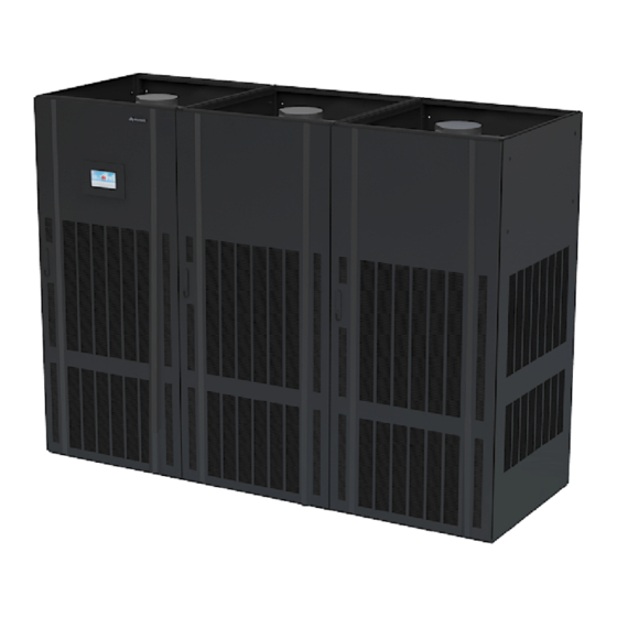
Page 2: Product Overview
Standby: 20.7 A/20.7 A Standby: C40/C40 Standby: 4 x 4 mm /4 x 6 mm -C190 route Equipotential Ground Cable Equipotential ground cable: 6 mm outdoor copper cable. Copyright © Huawei Digital Power Technologies Co., Ltd. 2022. All rights reserved. -
Page 3: Installing The Cabinet
• The equipment is charged with nitrogen before delivery. Rotate the exhaust valve counterclockwise. If there is a hiss sound, the system is well sealed, and you need to open the exhaust valve to exhaust the nitrogen. If there is no hiss sound, contact Huawei technical support. - Page 4 Downflow Upflow Removing the Pallet 1. For downflow units, remove the fan maintenance baffle plate at the front door before removing the bolts. 2. For a single-door and double-dour cabinet, remove the four screws from both sides. Open the front door and remove the rear door. Remove the bolts that secure the cabinet and the pallet using a 19# socket wrench.
- Page 5 Securing the Equipment For a single-door and double-door cabinet, tighten the four screws on both sides. 1. Secure the base to the ground using the six expansion bolts. 2. Move the cabinet onto the base. Secure the cabinet to the base using six bolts. Install a shock pad between the base and the cabinet.
- Page 6 b. Remove the six screws from the beams on both sides of the fan, and remove the two screws on the connecting piece between the fan and the bottom of the cabinet. Remove the beams and connecting piece. When removing the fan and connecting piece between the fans and the bottom plate, hold the fan to prevent it from rotating automatically.
- Page 7 Hole Positions Downflow (1) Drainpipe hole (2) Signal cable hole (3) Chilled water inlet pipe hole (4) Humidifier water inlet pipe hole (5) Chilled water outlet pipe hole (6) Active power cable hole (7) Standby power cable hole Upflow (1) Drainpipe hole (2) Chilled water inlet pipe hole (3) Chilled water outlet pipe hole (4) Humidifier water inlet pipe hole...
- Page 8 Connecting Water Inlet and Outlet Pipelines 1. Wrap thermal insulation foam around the whole pipes after pipes are connected. 2. Due to the hardening property of yellow adhesive, nitrogen injection and pressure preserve should be operated 8 hours after the adapter is connected. 1.
- Page 9 Connecting the Drainpipe Downflow Connection method (1) Drainpipe Upflow (1) Drainpipe (Optional) Leakage Test with Nitrogen • If the pressure decreases, apply soapy water on the pipes, especially pipe joints to check for any leakage. • If the pressure is stable, wrap all pipes and connectors with thermal insulation foam. •...
- Page 10 Upflow Leakage Test with Water • To avoid blockage of the heat exchanger in the smart cooling product due to foreign matter from the main pipe during the construction, you are advised to clean the main pipe before water is supplied to the smart cooling product. Turn off the isolation valves on the water inlet and outlet pipes before the cleaning and turn them on afterwards.
-
Page 11: Connecting Cables
Connecting Cables • Cables must be routed in through cable clips. • Route and bind the cables along the beams and columns of the unit. • The cabinet has no input neutral wire. You can cut the blue neutral wire and wrap it using insulation tape. - Page 12 (Optional) Connecting the T/H Sensor Outside the Cabinet Downflow Upflow (1) T/H sensors outside the cabinet • The T/H sensors inside the cabinet are secured at the return air side and their UP ports are connected to the main control board. When connecting the T/H sensors outside the cabinet, connect the DOWN port of one T/H sensor inside the cabinet to the UP port of the next T/H sensor outside the cabinet as shown in the following figure.
- Page 13 (Optional) Connecting Teamwork and Monitoring Cables Name Description Running indicator Alarm indicator Reserved for MAC_CAN FE_1 port teamwork CAN teamwork and RS485 CAN_IN port monitoring cascading RS485/12V Connects a temperature and port humidity (T/H) sensor. Connects a WiFi module or USB port USB flash drive.
- Page 14 2. Connect teamwork and monitoring communications cables. The teamwork modes include FE teamwork and CAN teamwork. FE teamwork is recommended. FE teamwork support point-to-point communication, long-distance cascading, and group upgrade. If the number of units in a group is greater than 16, FE teamwork needs to be implemented by group.
- Page 15 • Connect the COM/FE port on the main control module of the last unit in each group to the RS485 port on the host. • Customers can purchase the NetEco (an ECC is required) or a third-party NMS as the monitoring system.
- Page 16 If the Modbus-TCP/SNMP protocol is used, customers can purchase the NetEco (a LAN switch is required) or a third-party NMS as the monitoring system. CAN Teamwork + RS485 Monitoring Networking Teamwork Monitoring Protocol Modbus-TCP It takes 3 x n seconds to collect data from n units. If the time required for the host to collect data from all units One teamwork network does not meet the performance requirements, group the...
- Page 17 (Optional) Installing the Cap (Applicable to Upflow Units) • It takes two persons to install the cap using a 2 m step ladder. • Before installing the cap, attach the thermal insulation foam in the accessories to the top beam of the smart cooling product, and ensure that the reserved holes in the thermal insulation foam are aligned with the holes in the beam.
-
Page 18: Installation Verification
Installation Verification Check Item Expected Result Actual Result The cabinet is installed properly, without any tilt. The cabinet Cabinet is secured to the base by using bolts. The foreign matter inside □ Passed □ Failed the cabinet, such as cable ties and stubs, has been cleaned up. The fan of the downflow unit is lowered and secured to the □... - Page 19 (Optional) Teamwork Settings All teamwork control parameters can be set on the master smart cooling product. Only Teamwork group No., Air conditioner address, Enable teamwork CAN resistor, Teamwork function and Networking mode can be set on slave smart cooling products. Other parameters of the slave units will be modified by the master unit synchronously.
- Page 20 (Optional) Setting Communications Parameters RS485 Monitoring Network Cable (Modbus-RTU Protocol) a. On the home screen, choose Settings > Comm Settings > Modbus Settings. The value should be consistent with that set on the NMS. b. Set the communication address. The communication addresses of two smart cooling products connecting to the same NMS must be unique.
-
Page 21: Appendix 1: Precautions Against Adding Glycol
Start Confirm precautions and check items Commissioning Select commissioning items interrupted (Handle the fault by Fail Indoor fan commissioning referring to the tips Success Fail displayed on (Optional) Electric heater commissioning the home screen. Success Fail Perform Chilled water valve commissioning wizard startup Success Fail... - Page 22 Huawei Digital Power Technologies Co., Ltd. Huawei Digital Power Antuoshan Headquarters Futian, Shenzhen 518043 People's Republic of China www.huawei.com...