Chapters
Table of Contents

Related Manuals for Toshiba BMS-IFBN1280U-E


Summary of Contents for Toshiba BMS-IFBN1280U-E
- Page 1 Installation Manual BN interface For commercial use BN interface Model name: BMS-IFBN1280U-E English Installation Manual Français Manuel d’installation Installationshandbuch Deutsch Manuale d’installazione Italiano...
-
Page 2: Table Of Contents
BN interface Installation Manual Contents Precautions for safety ........... . 2 Introduction. -
Page 3: Precautions For Safety
BN interface Installation Manual Precautions for safety The following instructions must be observed. • Carefully read these "Precautions for Safety" before installation, and perform installation work safely. • These precautions contain important information regarding safety. • After installation work, carry out an operation trial to confirm that there are no problems, and explain to the customer how to operate and maintain the system. -
Page 4: Introduction
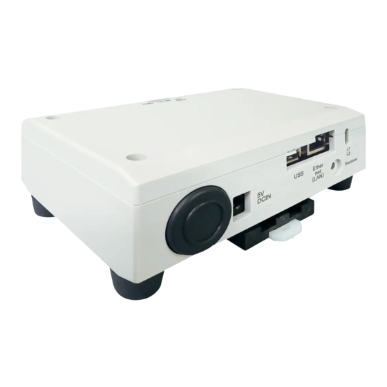
BN interface Installation Manual Introduction Overview The BN interface refers to equipment used for controlling Building Management Systems (Procured locally) and air conditioners “TU2C-LINK Uh Line (hereinafter, referred to as Uh Line) compatible models” through communications via a network to enable central control. - Page 5 BN interface Installation Manual (Power adapter) REQUIREMENT Power cable is not supplied for the BN Interface. Insert a two core power cord applicable to the standard of the country you use. Component Names Name Function 5V DCIN Connect the power adapter (For service) Ethernet (LAN) Connect to the Building Management System...
-
Page 6: Installation
BN interface Installation Manual Installation REQUIREMENT Do not install the unit in any of the following places. • Humid or wet place • Dusty place • Place exposed to direct sunlight • Place where there is a TV set or radio within one meter •... - Page 7 BN interface Installation Manual Installation Space and Maintenance Space A side space for connecting through cable inlets and an upper space for maintenance must be reserved before installation. The other sides can be adjacent to surrounding objects. – 6 – 6-EN...
-
Page 8: Power And Signal Line Connections
BN interface Installation Manual Power and signal line connections Cables Use the following cable for signal line connections. (Procured locally) Line Description Type 2-core shielded wires For Uh Line Wire size 1.25 mm , 1000 m max. total length including air conditioner wiring length Length 2.00 mm... - Page 9 BN interface Installation Manual Example of System Wiring Connections BN interface Building Management System Power adapter Power Supply Uh Line main bus Outdoor unit Outdoor unit Indoor unit Remote Indoor unit Remote controller controller – 8 – 8-EN...
-
Page 10: Settings
BN interface Installation Manual Settings 3-1. Switch setting SW300 Not used SW301 Test switch Set all bits to "OFF". SW302 Test button Not used during normal operation. SW100 Uh Line terminator resistor setting switch Set the Uh Line terminator resistor on the air conditioner side. Set SW100 to "OFF". SW700 Shutdown function / air-conditioning search mode function button Use this button to stop BACnet process and network process of the BN interface or to start up in the air-conditioning... -
Page 11: Led
BN interface Installation Manual 3-2. LED LED color POWER Power indicator LINK(Uh) Orange Uh Line communication status indicator ERROR Uh Line communication error indicator Green Communication status indicator in the BN interface Green BACnet communication status indicator BACnet communication status indicator, setting error indicator Factory default settings Item Factory default setting... -
Page 12: Test Run
BN interface Installation Manual Test run To perform test run of the BN interface, BACnet communication settings and the equipment data of the connected indoor units are required. Items to be set during trial run Equipment Item Setting method Use the DIP switch on the outdoor Outdoor unit Uh Line address Line address... -
Page 13: Setting Up Equipment Data In The Indoor Unit
BN interface Installation Manual 5-2. Setting up equipment data in the indoor unit Obtain the equipment data of the indoor unit that is controlled by the BN interface from the indoor unit via the Uh Line communication cable. Preparing to set up equipment data in the indoor unit •... - Page 14 Interface BN Manuel d’installation Contenu Précautions relatives à la sécurité ......... 14 Introduction.
-
Page 15: Précautions Relatives À La Sécurité
Interface BN Manuel d’installation Précautions relatives à la sécurité Respectez les instructions ci-dessous. • Lisez attentivement ces “Précautions relatives à la sécurité” avant l'installation et réalisez l'installation en toute sécurité. • Ces précautions contiennent des informations importantes concernant la sécurité. •... -
Page 16: Introduction
Interface BN Manuel d’installation Introduction Présentation L’interface BN fait référence à un équipement utilisé pour commander les systèmes de gestion des bâtiments (vendu séparément) et les climatiseurs « modèles compatibles TU2C-LINK Uh Line (ci-après nommés Uh Line) » par les communications via un réseau autorisant un contrôle centralisé. - Page 17 Interface BN Manuel d’installation (Adaptateur d'alimentation) EXIGENCE Le câble d’alimentation de l'interface BN n’est pas fourni. Utilisez un câble à deux conducteurs conformément à la réglementation du pays. Nom des composants Fonction 5V DCIN Connectez l'adaptateur secteur (Pour la maintenance) Ethernet (LAN) À...
-
Page 18: Installation
Interface BN Manuel d’installation Installation EXIGENCE N’installez pas l’unité dans un des emplacements suivants. • Humide ou moite • Poussiéreux • Exposé à la lumière directe du soleil • À moins d’un mètre d’un téléviseur ou d’une radio • Exposé à la pluie (extérieur, en rive de toit, etc.) ... - Page 19 Interface BN Manuel d’installation Espace requis pour l’installation et l’entretien Avant l’installation, vous devez allouer un espace latéral pour le branchement à travers les câbles d’entrée et un espace supérieur pour la maintenance. Les autres côtés peuvent être adjacents aux objets avoisinants. –...
-
Page 20: Connexion De L'alimentation Et De La Ligne De Signal
Interface BN Manuel d’installation Connexion de l'alimentation et de la ligne de signal Câbles Utilisez le câbles suivants pour la connexion de la ligne du signal. (Fourniture locale) N° Ligne Description Type Câbles blindés à 2 conducteurs Section Pour Uh Line 1,25 mm , 1000 m max. - Page 21 Interface BN Manuel d’installation Exemple de câblage du système Interface BN Système de gestion des bâtiments Adaptateur Alimentation d'alimentation électrique Bus principal Uh Line Unité extérieure Unité extérieure Unité Télécommande Unité Télécommande intérieure intérieure – 20 – 8-FR...
-
Page 22: Paramètres
Interface BN Manuel d’installation Paramètres 3-1. Réglage d'interrupteur SW300 Non utilisé SW301 Contacteur de test Réglez tous les bits sur "OFF". SW302 Touche de test Non utilisé pendant l'opération normale. SW100 Contacteur de réglage de la résistance de terminaison Uh Line Réglez la résistance de terminaison Uh Line sur le côté... -
Page 23: Témoin Del
Interface BN Manuel d’installation 3-2. Témoin DEL Témoin DEL Couleur du témoin DEL Utilisation POWER Rouge Indicateur d’alimentation LINK(Uh) Orange Indicateur d’état de communication Uh Line ERROR Rouge Indicateur d’erreur de communication Uh Line Vert Indicateur d'état de communication de l'interface BN Vert Indicateur d’état de communication BACnet Rouge... -
Page 24: Essai De Fonctionnement
Interface BN Manuel d’installation Essai de fonctionnement Pour réaliser un essai de fonctionnement de l'interface BN, vous avez besoin des réglages de communication BACnet et des données d'équipement des unités intérieures connectées. Éléments à régler pendant l’essai Équipement Élément Méthode de réglage Utilisez l’interrupteur DIP sur le Unité... -
Page 25: Mise En Place Des Données D'équipement Dans L'unité Intérieure
Interface BN Manuel d’installation 5-2. Mise en place des données d'équipement dans l'unité intérieure Obtenez es données d'équipement de l'unité intérieure qui est commandée par l'interface BN à partir de l'unité intérieure via le câble de communication Uh Line. Préparation à la mise en place des données d'équipement dans l'unité intérieure •... - Page 26 BN-Schnittstelle Installationshandbuch Inhalt Sicherheitshinweise ........... . . 26 Einleitung .
-
Page 27: Sicherheitshinweise
BN-Schnittstelle Installationshandbuch Sicherheitshinweise Die folgenden Anweisungen müssen unbedingt beachtet werden. • Lesen Sie diese „Sicherheitshinweise“ vor der Installation aufmerksam durch und achten Sie bei der Installation auf sichere Ausführung der Arbeiten. • Diese Vorsichtshinweise enthalten wichtige, die Sicherheit betreffende Informationen. •... -
Page 28: Einleitung
BN-Schnittstelle Installationshandbuch Einleitung Überblick Die BN-Schnittstelle bezieht sich auf Geräte, die zur Steuerung von Gebäudeverwaltungssystemen (lokal bereitgestellt) und Klimaanlagen „TU2C-LINK Uh Line (im folgenden Uh Line genannt) kompatibler Modelle“ durch Kommunikation über ein Netzwerk verwendet werden, um eine zentrale Steuerung zu ermöglichen. ... - Page 29 BN-Schnittstelle Installationshandbuch (Netzteil) ANFORDERUNG Netzkabel für die BN-Schnittstelle ist nicht mitgeliefert. Schließen Sie ein zweiadriges Netzkabel an, das die örtlich vorgeschriebenen Bedingungen erfüllt. Teilebezeichnungen Bezeichnung Funktion 5V DCIN Hier wird das Netzteil angeschlossen (Für Wartungszwecke) Ethernet (LAN) Verbindung zum Gebäudeverwaltungssystem Shutdown button Herunterfahren oder auf Klimagerät-Suchmodus schalten BACnet-Kommunikationsstatus-Anzeige...
-
Page 30: Installation
BN-Schnittstelle Installationshandbuch Installation ANFORDERUNG Installieren Sie das Gerät nicht in einer der folgenden Stellen. • Feuchter oder nasser Ort • Staubiger Ort • Ort, der direkter Sonneneinstrahlung ausgesetzt ist • Ort, wo es einen Fernseher oder Radio in einem Meter Abstand gibt •... - Page 31 BN-Schnittstelle Installationshandbuch Installationsplatz und Wartungsplatz Achten Sie bei der Montage darauf, dass an einer Seite genügend Platz für den Anschluss durch Kabelanschlussöffnungen und oben ein ausreichender Zugang für die Wartung vorhanden ist. Bei den übrigen Seiten ist kein Abstand zu nebenstehenden Geräten erforderlich.
-
Page 32: Strom- Und Signalkabelanschlüsse
BN-Schnittstelle Installationshandbuch Strom- und Signalkabelanschlüsse Kabel Verwenden Sie die folgenden Kabel für Signalleitungen. (lokal bereitgestellt) Leitung Beschreibung 2-adriges abgeschirmtes Kabel Für Uh Line Drahtgrößenzahl 1,25 mm , 1000 m max. Gesamtlänge einschließlich Klimageräte-Verkabelungslänge Länge 2,00 mm , 2000 m max. LAN-Kabel (höher als Kategorie 5, UTP) Die sachgerechte Verwendung von Straight-Kabel/Cross-Kabel muss dem ®... - Page 33 BN-Schnittstelle Installationshandbuch Beispiel einer Anlagenverkabelung BN-Schnittstelle Gebäudeverwaltungssystem Netzteil Stromversorgung Uh Line-Hauptbus Außengerät Außengerät Innengerät Fernbedienung Innengerät Fernbedienung – 32 – 8-DE...
-
Page 34: Einstellungen
BN-Schnittstelle Installationshandbuch Einstellungen 3-1. Schaltereinstellung SW300 Nicht verwendet Testschalter Stellt alle Bits auf „OFF“ (aus). SW302 Test-Taste Keine Verwendung beim Normalbetrieb. SW100 Einstellschalter für Uh Line-Abschlusswiderstand Stellen Sie den Uh Line-Abschlusswiderstand an der Seite des Klimageräts ein. Stellen Sie SW100 auf „OFF“ (aus). SW700 Herunterfahren-Funktion / Klimaanlagen-Suchmodus-Funktionstaste Verwenden Sie diese Taste zum Stoppen des BACne-Prozesses und des Netzwerk-Prozesses an der BN-... -
Page 35: Led
BN-Schnittstelle Installationshandbuch 3-2. LED LED-Farbe Verwendung POWER Stromversorgungsanzeige LINK(Uh) Orange Statusanzeige für Uh Line-Kommunikation ERROR Fehleranzeige für Uh Line-Kommunikation Grün Kommunikationsstatus-Anzeige in der BN-Schnittstelle Grün BACnet-Kommunikationsstatus-Anzeige BACnet-Kommunikationsstatus-Anzeige, Einstellfehleranzeige Werkseinstellungen Gegenstand Werkseinstellung IP-Adresse 192.168.1.100 IP-Adresse Subnet-Maske 255.255.255.0 UDP-Anschluss 47808 (0xBAC0) Geräteobjekt-Instanznummer Adresseneinstellung-Schalter Testschalter Alle AUS... -
Page 36: Testlauf
BN-Schnittstelle Installationshandbuch Testlauf Zum Ausführen eines Testlaufs der BN-Schnittstelle sind die BACnet-Kommunikationseinstellungen und die Gerätedaten des angeschlossenen Innengeräts erforderlich. Elemente, die während des Testlaufs eingestellt werden müssen Gerät Element Einstellmethode Verwenden Sie den DIP-Schalter auf Außengerät Uh Line-Adresse Line-Adresse der Platine des Außengeräts. Line-Adresse Verwenden Sie die Adresseinstellfunktion der... -
Page 37: Einstellen Der Gerätedaten Im Innengerät
BN-Schnittstelle Installationshandbuch 5-2. Einstellen der Gerätedaten im Innengerät Erhalten Sie die Gerätedaten des Innengeräts, das von der BN-Schnittstelle gesteuert wird vom Innengerät über das Uh Line- Kommunikationskabel. Vorbereitung zum Einrichten von Gerätedaten im Innengerät • Zentralsteueradresse muss im zum Steuern gewünschten Innengerät eingestellt werden. Informationen zur Einrichtung der Adresse finden Sie in der Einbauanleitung jedes Innengeräts. - Page 38 Interfaccia BN Manuale d’installazione Indice Precauzioni per la sicurezza ..........38 Introduzione .
-
Page 39: Precauzioni Per La Sicurezza
Interfaccia BN Manuale d’installazione Precauzioni per la sicurezza È necessario rispettare le istruzioni che seguono. • Leggere attentamente queste “Precauzioni per la sicurezza” prima dell’installazione, ed eseguire il lavoro di installazione in condizioni di sicurezza. • Queste precauzioni contengono importanti informazioni sulla sicurezza. •... -
Page 40: Introduzione
Interfaccia BN Manuale d’installazione Introduzione Panoramica L’interfaccia BN indica l’apparecchiatura utilizzata per controllare sistemi di gestione edifici (approvvigionati in loco) e condizionatori d’aria di “modelli compatibili con TU2C-LINK Uh Line (d’ora in avanti indicata come Uh Line)” tramite le comunicazioni effettuate attraverso una rete per abilitare il controllo centrale. - Page 41 Interfaccia BN Manuale d’installazione (Adattatore di alimentazione) REQUISITO L’interfaccia BN viene fornita senza cavo di alimentazione. Utilizzarne uno a due conduttori conforme allo standard vigente nel paese d’utilizzo. Nome delle parti Nome Funzione 5V DCIN Connessione dell’adattatore di alimentazione (Per il servizio d’assistenza) Ethernet (LAN) Connessione al sistema di gestione edificio...
-
Page 42: Installazione
Interfaccia BN Manuale d’installazione Installazione REQUISITO L’apparecchio non deve essere installato. • In luoghi umidi • In luoghi polverosi • In luoghi esposti direttamente alla luce solare • Entro un metro da televisori o apparecchi radio • In luoghi battuti dalla pioggia (all’esterno, sotto le grondaie e così via) ... - Page 43 Interfaccia BN Manuale d’installazione Spazio d’installazione e per manutenzione Prima dell’installazione, lasciare uno spazio laterale per il collegamento degli ingressi dei cavi e uno spazio superiore per la manutenzione. Gli altri lati possono essere adiacenti agli oggetti circostanti. – 42 – 6-IT...
-
Page 44: Collegamenti Di Alimentazione E Di Comunicazione
Interfaccia BN Manuale d’installazione Collegamenti di alimentazione e di comunicazione Cavi Per il collegamento della linea del segnale usare i seguenti cavi. (da approvvigionare in loco) Linea Descrizione Tipo Cavo schermato a due conduttori Connessione Dimensioni del Lunghezza totale 1,25 mm , massimo 1000 m Uh Line... - Page 45 Interfaccia BN Manuale d’installazione Esempio di connessione dei cavi del sistema Interfaccia BN Sistema di gestione edificio Adattatore di Alimentazione alimentazione elettrica Bus principale Uh Line Unità esterna Unità esterna Unità interna Telecomando Unità interna Telecomando – 44 – 8-IT...
-
Page 46: Impostazioni
Interfaccia BN Manuale d’installazione Impostazioni 3-1. Impostazione degli interruttori SW300 Non utilizzato SW301 Prova di funzionamento Impostare tutti i bit nella posizione “OFF”. SW302 Pulsante di prova Non utilizzato durante il funzionamento normale. SW100 Selezione della resistenza di terminazione Uh Line Applicare la resistenza sul lato condizionatore. -
Page 47: Led
Interfaccia BN Manuale d’installazione 3-2. LED Colore del LED Utilizzo POWER Rosso Indicatore di alimentazione LINK(Uh) Arancione Indicatore di stato della comunicazione Uh Line ERROR Rosso Indicatore di errore della comunicazione Uh Line Verde Indicatore di stato della comunicazione dell’interfaccia BN Verde Indicatore di stato della comunicazione BACnet Indicatore di stato della comunicazione BACnet e degli errori... -
Page 48: Prova Di Funzionamento
Interfaccia BN Manuale d’installazione Prova di funzionamento Per effettuare la prova di funzionamento dell’interfaccia BN è innanzi tutto necessario impostare la comunicazione BACnet e i dati nelle unità interne collegate. Voci da impostare durante il collaudo Equipaggiamento Voce Metodo di impostazione Utilizzare l’interruttore DIP sulla Unità... -
Page 49: Impostazione Dei Dati Nelle Unità Interne
Interfaccia BN Manuale d’installazione 5-2. Impostazione dei dati nelle unità interne È innanzi tutto necessario ottenere per mezzo del cavo di comunicazione Uh Line i dati delle unità interne controllate dall’interfaccia BN. Preparazione all’impostazione dei dati nelle unità interne • Impostare l’Indirizzo di controllo centralizzato nelle unità interne da controllare. Per istruzioni a questo riguardo si rimanda al manuale d’installazione di ciascuna unità. - Page 50 Interfaccia BN Manuale d’installazione – 49 – 13-IT...
- Page 51 MEMO ................................................................................................................................................................................................................................................................................................................................................................................................................................................................................................................................................................................................................................– 50 –...
- Page 52 DEC0209150...