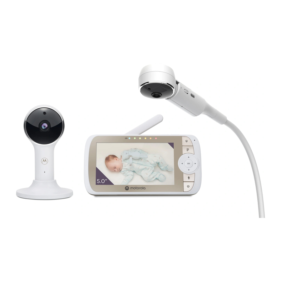
Contents Inside Box
- Baby Unit (Camera)
![]()
- Magnetic Mount
![]()
- Parent Unit
![]()
- Power Adapters
![]()
- Quick Start Guide
![]()
- Top Clamp
![]()
- Bottom Clamp
![]()
- Gooseneck
![]()
- 4-Poles with stand base
![]()


Strangulation hazard. Children have STRANGLED in cords. Keep this cord out of the reach of children (more than 1 metre away). Do not remove the tags from the AC Adapters. Only use the AC Adapters provided.
Setting up your Digital Video Baby Monitor
Connecting the Power Supply for the Baby Unit

- Note: Only use the supplied power adapter (DC5V/1000mA).
Fixing magnetic mount on the wall

Connecting the Power Supply of the Parent Unit

Desktop Stand of the Parent Unit

Basic operation of the keys
| Parent unit | ||
 | ON/OFF button | Press and hold to switch the Parent Unit ON/OFF. |
 | UP/DOWN buttons | Press to tilt the camera image upward or downward. Press to adjust menu setting when menu is active. |
 | LEFT/RIGHT buttons | Press to pan the camera image left or right. Press to access menu options when menu is active. |
 | MENU button | Press to open menu options or exit the menu. |
 | OK button | Press to confirm a selection. |
 | VIDEO button | Press to turn the LCD screen ON/OFF. |
 | TALK button | Press and hold to talk to your baby. |
 | Volume button | Press -/+ to select volume level of the Parent Unit. |
 | RESET button | Press and hold with a small pin to reset the unit. |
| Baby Unit | ||
 PAIR button PAIR button | Press and hold to pair with the parent unit or Motorola Nursery Setup. | |
Setting up the Baby Unit for Wi-Fi® internet viewing
Install Motorola Nursery App


- Scan the QR code with your smart device and download Motorola Nursery App from the App Store for iOS devices or from the Google Play™ Store for Android™ devices.
View on Compatible Smartphones and Tablets

Please take note of the following minimum system requirements:
Smartphones/Tablets: iOS 10.0, Android™ 7.0
Wi-Fi® requirements:
At least 0.6 Mbps upload bandwidth per Smart Montitoring Companion, test your Internet speed at: http://www.speedtest.net/
Installation of Cot mount
A cot mount with cable management is included which mounts directly to most cots to allow better viewing. Assemble and install the cot mount using the following steps.
- Join the 4 poles and the support base together as the diagram shown. (Fig. 1a, 1b)

Note:
Each pole is connected with power cord inside, manage with care the power cords when removing the poles from the box and during installation. - The Top Clamp is delivered by default for vertical clamping on the top rail of the cot, to clamp horizontally on the slates of the cot, please unfasten and remove the tiny knob completely from the Top Clamp assembly (Fig. 2a), remove the Top Clamp from the assembly and re-orient the Top Clamp with the long open end pointing at left hand side (Fig. 2b), then reinsert into the assembly, fasten the tiny knob back to the assembly until the Top Clamp is securely locked.

- Fasten the top clamp either vertically on the upper rail (Fig. 2c) or the slats horizontally(Fig. 2d).
![]()
- Unlock the knob then open the top clamp and bottom clamp, move the supporting poleinto the clamps. (Fig. 3a)
Fig. 3a
![]()
- Place then press the bottom clamp below against the lower rail, the stand base is springloaded. Push the lower pole downward before closing the bottom clamp with knob. This is to allow the lower clamp to exerting clamping force on the lower rail (Fig. 3b).
Fig. 3b
![]()
- Fasten the knobs to close the holders of the top and bottom clamps so that the supportpoles stand firm and straight, ensure that the supporting poles are positioned stable on the top rail or slates. (Fig. 4a, 4b).

![warning]() Choking Hazard:
Choking Hazard:
May contain Small Parts. Parents exercise caution and keep children under 5 from the installation. - Install the flexible gooseneck extension into the top post. Youwill hear the click noise when all the sections are properly connected (Fig. 5a).
Fig. 5a
![]()
- Insert the camera unit into the housing at the end of the flexiblegooseneck extension, make sure the camera is magnetic mounted. Connect the power adapter plug to the camera unit power socket then close the cover (Fig. 5b, 5c)

- Insert the DC plug into the power socket of the Cot mount, and connect the poweradapter to a suitable power socket. (Fig. 6a).
Fig. 6a
![]()
- Power on the camera unit then view the image through the parentunit. Adjust the flexible gooseneck and select from the parent unit different zoom factor (1x, 1.5x or 2x) for optimal view over the cot (Fig. 6b).
Fig. 6b
![]()


 Choking Hazard:


General Information
If your product is not working properly, сontact Customer Service: motorolanursery.com/support
Imported & Distributed by A.I.&E., Adriaan Mulderweg 9-11, 5657 EM Eindhoven, The Netherlands and Edco UK Ltd, 1st Floor, Two Chamberlain Square, Birmingham, B3 3AX, UK.
© 2021 Motorola Mobility LLC. All rights reserved.

Documents / Resources
References
![www.apple.com]() App Store - Apple
App Store - Apple![play.google.com]() Google Play
Google Play![www.speedtest.net]() Speedtest by Ookla - The Global Broadband Speed Test
Speedtest by Ookla - The Global Broadband Speed Test![motorolanursery.com]() Motorola Nursery | Support for nursery products
Motorola Nursery | Support for nursery products
Download manual
Here you can download full pdf version of manual, it may contain additional safety instructions, warranty information, FCC rules, etc.


