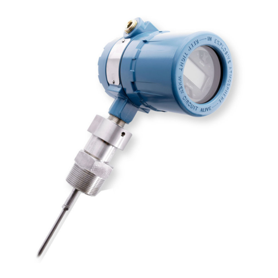
Emerson Rosemount 3300 Quick Start Manual
Level transmitter guided wave radar
Hide thumbs
Also See for Rosemount 3300:
- Reference manual (146 pages) ,
- Quick start manual (52 pages) ,
- Reference manual (134 pages)

Related Manuals for Emerson Rosemount 3300


Summary of Contents for Emerson Rosemount 3300
- Page 1 Quick Start Guide 00825-0100-4811, Rev JG November 2022 ™ Rosemount 3300 Level Transmitter Guided Wave Radar...
-
Page 2: Table Of Contents
Quick Start Guide November 2022 Contents About this guide...........................3 Mount the transmitter head/probe....................7 Set jumpers and switches......................17 Connect wiring and power up.....................19 Configure........................... 25 Environmental conditions......................32 Product certifications......................... 33 Rosemount 3300 Level Transmitter... -
Page 3: About This Guide
November 2022 Quick Start Guide About this guide This start guide provides basic guidelines for the Rosemount 3300 Level Transmitter. Refer to Rosemount 3300 Level Transmitter Reference Manual for more instructions. The manual and this Quick Start Guide (QSG) are also available electronically on Emerson.com/Rosemount. - Page 4 The electronics enclosures are category 2G or 2D equipment. The probes not covered with plastic and not made of titanium, are category 1G or 1D. The plastic covered probes or probes made of titanium, are only category 1G equipment. Rosemount 3300 Level Transmitter...
- Page 5 November 2022 Quick Start Guide Figure 1-1: Equipment Category Category 2D Category 1D Probes according to table Applicable marking: II 1/2 D Ex ia IIIC T 85 °C…T 450 °C Da / Ex tb [ia Da] IIIC T85 °C…T450 °C Db Category 2G Category 1G All probes possible...
- Page 6 The Material of Construction Code can be found in the ninth character position of the transmitter model code (for example 330xxxxx1xxxxxxxx). Probes and flanges containing >7.5 percent magnesium or zirconium are not allowed in explosive dust atmosphere. Contact your Emerson sales representative for more information. Probes and flanges containing light metals...
-
Page 7: Mount The Transmitter Head/Probe
November 2022 Quick Start Guide Mount the transmitter head/probe Tank connection with flange Prerequisites Note PTFE covered probes must be handled carefully to prevent damage to the coating. Procedure 1. Place a suitable gasket on top of the tank flange. Note Gasket should not be used for PTFE covered probe with protective plate. - Page 8 3. Tighten bolts and nuts with sufficient torque for the flange and gasket choice. 4. Loosen the nut that connects the transmitter head to the probe slightly. 60 mm 5. Rotate the transmitter housing so the cable entries/display face the desired direction. Rosemount 3300 Level Transmitter...
- Page 9 November 2022 Quick Start Guide 6. Tighten the nut. Torque 30 ft-lb (40 Nm) 60 mm Threaded tank connection Prerequisites Note PTFE covered probes must be handled carefully to prevent damage to the coating. Procedure 1. For adapters with BSPP (G) threads, place a suitable gasket on top of the tank flange.
- Page 10 3. Lower the transmitter and probe into the tank. 4. Loosen the nut that connects the transmitter head to the probe slightly. 60 mm 5. Screw the adapter into the process connection. 52 mm / 60 mm Rosemount 3300 Level Transmitter...
- Page 11 November 2022 Quick Start Guide 6. Rotate the transmitter housing so the cable entries/display face the desired direction. 7. Tighten the nut. Torque 30 ft-lb (40 Nm) 60 mm Quick Start Guide...
- Page 12 PTFE covered probes must be handled carefully to prevent damage to the coating. Procedure 1. Place a suitable gasket on top of the tank flange. 2. Lower the transmitter and probe into the tank. 3. Tighten the clamp to the recommended torque (see the manufacturer’s instruction manual). Rosemount 3300 Level Transmitter...
- Page 13 November 2022 Quick Start Guide 4. Loosen the nut that connects the transmitter head to the probe slightly. 60 mm 5. Rotate the transmitter housing so the cable entries/display face the desired direction. 6. Tighten the nut. Torque 30 ft-lb (40 Nm) 60 mm Quick Start Guide...
- Page 14 Quick Start Guide November 2022 Bracket mounting Procedure 1. Mount the bracket to the pipe/wall. On pipe: A. Horizontal pipe B. Vertical pipe On wall: 2. Mount the transmitter with probe to the bracket. Rosemount 3300 Level Transmitter...
- Page 15 November 2022 Quick Start Guide Install remote housing Procedure 1. Carefully remove the transmitter. 2. Mount the probe on tank. A. Gasket 3. Mount the remote connection on the probe. Torque 30 ft-lb (40 Nm) 55 mm Quick Start Guide...
- Page 16 Quick Start Guide November 2022 4. Mount the bracket to the pipe. A. Horizontal pipe B. Vertical pipe 5. Fasten the housing support. 6. Mount the transmitter head. Torque 30 ft-lb (40 Nm) Rosemount 3300 Level Transmitter...
-
Page 17: Set Jumpers And Switches
November 2022 Quick Start Guide Set jumpers and switches Set alarm and write protection on the circuit board If alarm and security jumpers are not set, the transmitter operates with the default alarm condition HIGH and Security OFF. Prerequisites Write protection must be set after configuration. Procedure 1. - Page 18 Quick Start Guide November 2022 Figure 3-2: LCD Display Rosemount 3300 Level Transmitter...
-
Page 19: Connect Wiring And Power Up
November 2022 Quick Start Guide Connect wiring and power up Power supply ® For HART , the input voltage is 11-42 V (11-30 V in IS applications, 16-42 V ® in Explosion-proof / Flameproof applications). For Modbus , the input voltage is 8-30 V. - Page 20 D. Power supply E. HART modem F. PC G. Maximum voltage: U = 250 V H. HART: U = 42.4 V Note Rosemount 3300 Level Transmitters with Flameproof/Explosion-proof HART Output have a built-in barrier; no external barrier needed. Rosemount 3300 Level Transmitter...
- Page 21 November 2022 Quick Start Guide Figure 4-3: Intrinsically Safe HART Output A. Rosemount 3300 Level Transmitter B. Handheld communicator C. R = 250 Ω D. Power supply E. HART modem F. PC G. DCS H. Approved IS barrier IS Parameters: U...
- Page 22 G. HART - H. If the unit is the last transmitter on the bus, a 120 Ω termination resistor is required. Note Rosemount 3300 Level Transmitters with Flameproof/Explosion-proof Modbus Output have a built-in barrier; no external barrier needed. Rosemount 3300 Level Transmitter...
- Page 23 November 2022 Quick Start Guide Load limitations ® For HART communication, a minimum loop resistance of 250 Ω is required. Maximum loop resistance is determined by the voltage level of the external power supply, as given by the following diagrams: Figure 4-5: Non-Hazardous Installations A.
- Page 24 5. Connect the cable wires (see Wiring diagram). 6. If applicable, use the enclosed metal plug to seal any unused port. 7. Replace the cover and tighten. 8. Tighten the cable gland. 9. Connect the power supply. Rosemount 3300 Level Transmitter...
-
Page 25: Configure
If the transmitter is pre-configured at the factory, this section is only necessary to change or verify the settings. Configuration of the Rosemount 3300 Level Transmitter can be done either with a handheld communicator, the AMS Device Manager, or Radar ®... - Page 26 The Help function of the RCT can be reached from the menu or by pressing the F1 key. Configuration using the Wizard Configuration of a Rosemount 3300 Level Transmitter can be done using the installation Wizard for detailed guidance. Procedure 1.
- Page 27 November 2022 Quick Start Guide Configuration using the Setup Function If you are already familiar with the configuration procedure, or if you want to change settings, you may use the setup function. Procedure 1. Make sure that the Tools Bar is open (Project Bar is ticked within View).
- Page 28 In the Primary Variable field, the measuring parameter is entered for the analog signal. ® More variables can be assigned if the superimposed digital HART signal or a ™ HART Tri-loop is used. See the Rosemount 3300 Level Transmitter Reference Manual. Rosemount 3300 Level Transmitter...
- Page 29 November 2022 Quick Start Guide ® Modbus setup If the transmitter has the Modbus option, configuration of the communication parameters can be set. Quick Start Guide...
- Page 30 Set Probe Angle • If Remote Housing is mounted, set the Remote Housing length (setting ™ not available in DD/DTM Miscellaneous settings • Set Vapor Dielectric value (if needed) • Set Upper Product Dielectric value (interface measurements only) Rosemount 3300 Level Transmitter...
- Page 31 November 2022 Quick Start Guide Additional configuration to fine-tune performance To fine-tune the transmitter’s performance, it is recommended the Trim Near Zone function be executed after configuration is finished. For detailed information on how to trim the near zone, see the Rosemount 3300 Level Transmitter Reference Manual.
-
Page 32: Environmental Conditions
National deviations may apply, see Product certifications. Process temperature restrictions When the Rosemount 3300 is installed in high temperature applications, consider the maximum ambient temperature. Tank insulation should not exceed 4 in. (10 cm). Figure 6-1 shows the maximum ambient temperature vs. process temperature. -
Page 33: Product Certifications
A copy of the EU Declaration of Conformity can be found at the end of the document. The most recent revision of the EU Declaration of Conformity can be found at Emerson.com/Rosemount. Ordinary location certification As standard, the transmitter has been examined and tested to determine... - Page 34 30 V 130 mA 0 nF 0 mH Canada 7.5.1 E6 Explosionproof, Dust-Ignitionproof Certificate CSA02CA1250250X Standards CSA C22.2 No.0-M91, CSA C22.2 No.25-1966 (R2009), CSA C22.2 No.30-M1986 (R2012), CSA C22.2 No.94- M91, CSA C22.2 No.142-M1987, CAN/CSA-C22.2 No. Rosemount 3300 Level Transmitter...
- Page 35 November 2022 Quick Start Guide 60079-0:15, CAN/CSA-C22.2 No. 60079-11:14, CSA C22.2 No. 213-M1987 (R2013), CAN/CSA C22.2 No. 60529:05 Markings CL I, Div.1, GP C, D; CL II, Div.1 & 2, GP G & COAL DUST; CL III, Div.1 T4, MAX. AMB. TEMP. +85°C HAZ.
- Page 36 3. For probes and flanges containing light metals, an ignition hazard due to impact or friction needs to be avoided according to EN 60079-0 clause 8.3, when used as EPL Ga/Gb equipment. Rosemount 3300 Level Transmitter...
- Page 37 November 2022 Quick Start Guide 4. Conditions which may adversely affect the material of the partition wall shall be avoided, see instructions for details. Temperature class / Maximum process Maximum ambient Maximum surface temperature temperature temperature T6 / T 85 °C +75 °C +75 °C T5 / T 100 °C...
- Page 38 T4 / T 135 °C +125 °C +75 °C T3 / T 200 °C + 190 °C +75 °C T2 / T 300 °C +285 °C +65 °C T1 / T 450 °C + 400 °C +55 °C Rosemount 3300 Level Transmitter...
- Page 39 November 2022 Quick Start Guide 7.7.2 I7 IECEx Intrinsic Safety Certificate IECEx BAS 12.0062X Standards IEC 60079-0:2017, IEC 60079-11:2011 Markings Ex ia IIC T4 Ga (-50°C ≤ Ta ≤ +70°C) Specific Conditions for Safe Use (X): 1. The equipment is not capable of withstanding the 500V test as defined in EN60079-11.
- Page 40 GB 3836.1-2010, GB 3836.4-2010, GB 3836.20-2010 Markings Ex ia IIC T4 (-50°C ≤ Ta ≤ +70°C), Specific Conditions for Safe Use (X): 1. See certificate for Specific Conditions. Entity parameters 30 V 130 mA 0 nF 0 mH Rosemount 3300 Level Transmitter...
- Page 41 November 2022 Quick Start Guide 7.10 Technical Regulations Customs Union (EAC) TR CU 020/2011 “Electromagnetic Compatibility of Technical Products” TR CU 032/2013 “On safety of equipment and vessels under pressure” ЕАЭC RU С-US.АД07.В.00770/19 Certificate TR CU 012/2011 “On safety of equipment intended for use in explosive atmospheres”...
- Page 42 Same as IECEx (I7) 7.14 Combinations Combination of E5 and E6 7.15 Additional certifications 7.15.1 U1 Overfill prevention Certificate Z-65.16-416 Application TÜV tested and approved by DIBt for overfill prevention according to the German WHG regulations. Rosemount 3300 Level Transmitter...
- Page 43 November 2022 Quick Start Guide 7.16 Pattern approval GOST Belarus Certificate RB-03 07 2765 10 GOST Kazakhstan Certificate KZ.02.02.03473-2013 GOST Russia Certificate SE.C.29.010.A GOST Uzbekistan Certificate 02.2977-14 China Pattern Approval Certificate 2009-L256 7.17 Conduit plugs and adapters IECEx Flameproof and Increased Safety Certificate IECEX UL 18.0016X Standards...
- Page 44 4. Suitability of the temperature of the devices is to be determined during end-use with suitably rated equipment. 5. The Ex Blanking Elements have been evaluated for use in an ambient temperature range of -60 °C to +125 °C. Rosemount 3300 Level Transmitter...
- Page 45 November 2022 Quick Start Guide 7.18 Installation drawings Figure 7-1: 9150077-944 - System Control Drawing Quick Start Guide...
- Page 46 Quick Start Guide November 2022 Figure 7-2: 9150077-945 Installation Drawing Rosemount 3300 Level Transmitter...
- Page 47 November 2022 Quick Start Guide 7.19 EU Declaration of Conformity Figure 7-3: EU Declaration of Conformity Quick Start Guide...
- Page 48 Quick Start Guide November 2022 Rosemount 3300 Level Transmitter...
- Page 49 November 2022 Quick Start Guide Quick Start Guide...
- Page 50 GB/T 26572. 意 所 GB/T 26572 X: Indicate that said hazardous substance contained in at least one of the homogeneous materials used for this part is above the limit requirement of GB/T 26572. 意 所 GB/T 26572 Rosemount 3300 Level Transmitter...
- Page 51 November 2022 Quick Start Guide Quick Start Guide...
- Page 52 For more information: Emerson.com © 2022 Emerson. All rights reserved. Emerson Terms and Conditions of Sale are available upon request. The Emerson logo is a trademark and service mark of Emerson Electric Co. Rosemount is a mark of one of the Emerson family of companies.