Hitachi HX-RIO3 Series User Manual
Modbus rtu network adapter light
Hide thumbs
Also See for HX-RIO3 Series:
- Manual (68 pages) ,
- User manual (63 pages) ,
- User manual (16 pages)
Table of Contents
Quick Links
Table of Contents

Related Manuals for Hitachi HX-RIO3 Series


Summary of Contents for Hitachi HX-RIO3 Series
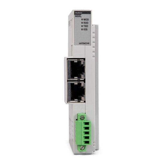
- Page 1 HX-RIO3 Series MODBUS RTU Network Adapter Light RIO3-MBRL User manual...
- Page 2 HX-RIO3 Series DOCUMENT CHANGE SUMMARY PAGE REMARKS DATE EDITOR 1.00 New Document Feb 2021 Faber...
-
Page 3: Table Of Contents
HX-RIO3 Series Contents 1. Important Note .......................... 5 1.1. Safety Instruction ........................6 1.1.1. Symbols ..........................6 1.1.2. Safety Notes ........................6 1.1.3. Certification ......................... 6 2. Specification..........................7 2.1. Interface ..........................7 2.1.1. RIO3-MBRL .......................... 7 2.2. Specification ........................... 8 2.2.1. - Page 4 HX-RIO3 Series 6.1.1. Comparison of MODBUS TCP/UDP and MODBUS/RTU ..........20 6.1.2. MODBUS TCP/ UDP MBAP Header .................. 21 6.2 Supported MODBUS Function Codes .................. 21 6.2.1. 1(0x01) Read Coils ......................22 6.2.2. 2(0x02) Read Discrete Inputs ................... 22 6.2.3. 3(0x03) Read Holding Registers ..................23 6.2.4.
-
Page 5: Important Note
In no event will HITACHI be responsible or liable for indirect or consequential damages resulting from the use or application of this equipment. -
Page 6: Safety Instruction
HX-RIO3 Series 1.1. Safety Instruction 1.1.1. Symbols Information about practices or circumstances that can cause an explosion in a hazardous environment, which may lead to personal injury or death property damage, or economic loss. Identifies information that is critical for successful application and understanding of the Product. -
Page 7: Specification
HX-RIO3 Series 2. Specification 2.1. Interface 2.1.1. RIO3-MBRL Pin No. Signal Description System Power, 24V System Power, 24V Field Power, Ground Field Power, 24V... -
Page 8: Specification
HX-RIO3 Series 2.2. Specification 2.2.1. General Specification General specification UL System Power Supply voltage: 24Vdc nominal, Class 2 Supply voltage: 24Vdc nominal System Power Supply voltage range: 15~28.8Vdc Reverse polarity protection Power Dissipation 20mA typical @ 24Vdc Current for I/O Module 1.0A @ 5Vdc... -
Page 9: Interface Specification
HX-RIO3 Series 2.2.2. Interface Specification Interface Specification RIO3-MBRL (RS-485) Adapter Type Slave node (MODBUS Serial RTU/ASCII Server) Protocol MODBUS RTU and ASCII Max. Expansion Module 16 slots Max. Data Size (Input + Output) Max. Input 256 bytes / Output 256 bytes... -
Page 10: Led Indicator
HX-RIO3 Series 2.3. LED Indicator LED Function / Description LED Color Module Status Green/Red Physical Connection Green Exchange Data/Traffic Present Green Expansion Module Status Green/Red 2.3.1 MOD (Module Status LED) Status To indicate Not Powered Power is not supplied to the unit. -
Page 11: Dimension
HX-RIO3 Series 3. Dimension 3.1. RIO3-MBRL (mm) -
Page 12: Mechanical Set Up
HX-RIO3 Series 4. Mechanical Set Up 4.1. Total Expansion The number of the module assembly that can be connected is 16. So the maximum length is 214mm Exception. 4.2. Plugging and Removal of the Components As above figure in order to safeguard the RIO3 module from jamming, it should be fixed onto the DIN rail with locking level. -
Page 13: Modbus Electrical Interface
HX-RIO3 Series 5. MODBUS Electrical Interface Slot 16... -
Page 14: G-Bus System
HX-RIO3 Series 5.1. G-Bus System • Network Adapter Module The Network Adapter Module forms the link between the field bus and the field devices with the Expansion Modules. The connection to different field bus systems can be established by each of the corresponding Network Adapter Module, e.g. - Page 15 HX-RIO3 Series 5.2 G-Bus Pin Description Communication between the RIO3 series and the expansion module as well as system / field power supply of the bus modules is carried out via the internal bus. It is comprised of 6 data pin and 2 field power...
-
Page 16: Rio3-Mbrl Electrical Interface
HX-RIO3 Series 5.3. RIO3-MBRL Electrical Interface 5.3.1. RJ-45 Socket RJ-45 Signal Name Description RS485 + Transmit + RS485 − Transmit − Communication Ground − − − − Frame Ground Case Shield Shield RJ-45 Socket 5.3.2. MODBUS Dip Switch Setup DIP Switch... -
Page 17: Process Image Map
HX-RIO3 Series 5.3.3. Process Image Map An expansion module may have 3 types of data as I/O data, configuration parameter and memory register. The data exchange between Network Adapter and expansion modules is done via an I/O process image data by RIO3 Series protocol. -
Page 18: Example
HX-RIO3 Series 5.4. Example 5.4.1. Example of Input Process Image (Input Register) Map Input image data depends on slot position and expansion slot data type. Input process image data is only ordered by expansion slot position. Example slot configuration Slot... -
Page 19: Example Of Output Process Image (Output Register) Map
HX-RIO3 Series 5.4.2. Example of Output Process Image (Output Register) Map Output image data depends on slot position and expansion slot data type. Output process image data is only ordered by expansion slot position. Example slot configuration Slot Module Description... -
Page 20: Modbus Tcp/Udp Interface
HX-RIO3 Series 6. MODBUS TCP/UDP INTERFACE 6.1 MODBUS TCP/ UDP Protocol The MODBUS messaging service provides a Client/Server communication between devices connected on an Ethernet TCP/IP network. All MODBUS/TCP messages are sent via TCP on registered port 502. Refer to Modbus_Messaging_Implementation_Guide_V1_0a.pdf. -
Page 21: Modbus Tcp/ Udp Mbap Header
HX-RIO3 Series 6.1.2. MODBUS TCP/ UDP MBAP Header The MBAP (MODBUS Application Protocol) header contains the following fields. Fields Length Description Client Server Identification of a MODBUS Transaction Initialized by Recopied by the server from the 2bytes Request /Response Identifier... -
Page 22: 0X01) Read Coils
HX-RIO3 Series 6.2.1. 1(0x01) Read Coils This function code is used to read from 1 to 2000 contiguous status of coils in a remote device. The Request PDU specifies the starting address, i.e. the address of the first coil specified, and the number of coils. In the PDU Coils are addressed starting at zero. -
Page 23: 0X03) Read Holding Registers
HX-RIO3 Series • Response Field name Example Function Code 0x02 Byte Count 0x02 Output Status 0x80 Output Status 0x00 - In case of address 0x0015~0x0000 input bit value: 00000000_10000000. 6.2.3. 3(0x03) Read Holding Registers This function code is used to read the contents of a contiguous block of holding registers in a remote device. -
Page 24: 0X05) Write Single Coil
HX-RIO3 Series • Request Field name Example Function Code 0x04 Starting Address Hi 0x00 Starting Address Lo 0x00 Quantity of Resister Hi 0x00 Quantity of Resister Lo 0x02 • Response Field name Example Function Code 0x03 Byte Count 0x04 Input Register#0 Hi... -
Page 25: 0X06) Write Single Register
HX-RIO3 Series 6.2.6. 6 (0x06) Write Single Register This function code is used to write a single holding register in a remote device. Therefore, register numbered 1 is addressed as 0. The normal response is an echo of the request, returned after the register contents have been written. - Page 26 HX-RIO3 Series The data passed in the request data field is to be returned (looped back) in the response. The entire response message should be identical to the request. Sub-function Data Field (Request) Data Field (Response) Description 0x0000(0) Echo Request Data Sub-function 0x0001(1) Restart Communications Option The remote device could be initialized and restarted, and all its communications event counters are cleared.
-
Page 27: 0X0F) Write Multiple Coils
HX-RIO3 Series Sub-function 0x000F (15) Return Slave No Response Count The response data field returns the quantity of messages addressed to the remote device for which it has returned no response (neither a normal response nor an exception response), since its last restart, clear counters operation, or power–up. -
Page 28: 0X10) Read/Write Multiple Registers
HX-RIO3 Series 6.2.9. 16 (0x10) Read/Write Multiple Registers This function code is used to write a block of contiguous registers (1 to approx. 120 registers) in a remote device. The requested written values are specified in the request data field. Data is packed as two bytes per register. -
Page 29: 0X17) Read/Write Multiple Registers
HX-RIO3 Series 6.2.10. 23 (0x17) Read/Write Multiple Registers This function code performs a combination of one read operation, and one write operation in a single MODBUS transaction. The write operation is performed before the read. The request specifies the starting address and number of holding registers to be read as well as the starting address, number of holding registers, and the data to be written. -
Page 30: Modbus Special Register Map
(one address). 6.3.1 Adapter Identification Special Register (0x1000, 4096) Address Access Type, Size Description 0x1000(4096) Read 1word Vendor ID = 0x02E5 (741), HITACHI 0x1001(4097) Read 1word Device type = 0x000C, Network Adapter 0x1002(4098) Read 1word Product Code = 0x91A0... -
Page 31: Adapter Watchdog Time, Other Time Special Register (0X1020, 4128)
HX-RIO3 Series - String Type consists of valid string length (first 1word) and array of characters 6.3.2 Adapter Watchdog Time, other Time Special Register (0x1020, 4128) A watchdog timer can be configured for timeout periods up to 65535(1unit=100msec). The Watchdog timer... - Page 32 HX-RIO3 Series 0X80: ERR_WATCHDOG 0X02 : CONNECT_FAULT 0X03 : CONFIG_FAULT 0X04: NO_EXPANSION 0X05: INVALID_ATTR_VALUE 0X06: TOO_MUCH_DATA 0X07: VENDOR_ERROR 0X08: NOT_EXPECTED_SLOT 0X09: CRC_ERROR 0x111D(4381) Read 1word Adapter RIO3 Series Revision. * After the system is reset, the new “Set Value” action is applied.
-
Page 33: Expansion Slot Information Special Resister (0X2000, 8192)
HX-RIO3 Series 6.3.4 Expansion Slot Information Special Resister (0x2000, 8192) Each expansion slot has 0x20(32) address offset and same information structure. Slot#1 0x2000(8192)~0x201F(8223) Slot#2 0x2020(8224)~0x203F(8255) Slot#3 0x2040(8256)~0x205F(8287) Slot#4 0x2060(8288)~0x207F(8319) Slot#5 0x2080(8320)~0x209F(8351) Slot#6 0x20A0(8352)~0x20BF(8383) Slot#7 0x20C0(8384)~0x20DF(8415) Slot#8 0x20E0(8416)~0x20FF(8447) Slot#9 0x2100(8448)~0x211F(8479) Slot#10 0x2120(8480)~0x213F(8511) -
Page 34: Modbus Reference
HX-RIO3 Series + 0x02(+2) ** Read 1word Input start register address of input image word this slot. Input word’s bit offset of input image word this slot. + 0x03(+3) ** Read 1word + 0x04(+4) ** Read 1word Output start register address of output image word this slot. -
Page 35: Troubleshooting
HX-RIO3 Series 7. Troubleshooting How to diagnose by LED indicator LED Status Cause Action - No power - Check main power Cable All LED turns off - Contact Sales team and send - System power is not supplied. module for repair. -
Page 36: How To Diagnose When Device Couldn't Communicate Network
HX-RIO3 Series How to diagnose when device couldn't communicate network Inspection of wrong or omission cable connection. - Check status of cable connection for each node. - Check that all colour matches between connector and cable. - Check wire omission. -
Page 37: Product List
HX-RIO3 Series APPENDIX A A.1 Product List RIO3-Number Description ID (hex) Digital Input Module RIO3-XDP8 8 Points, Universal, 24Vdc, 10RTB 1238 RIO3-XDP16C 16 Points, Universal, 24Vdc, 20P connector 123F RIO3-XDP16T 16 Points, Universal, 24Vdc, 18RTB 12DF RIO3-XDP32C 32 Points, Universal, 24Vdc, 40P connector... -
Page 38: Glossary
HX-RIO3 Series RIO3-AYH4V 4CH, 0~10Vdc, 16Bits, 10RTB 4464 RIO3-AY8V 8CH, 0~10Vdc, 12Bits, 10RTB 4428 RIO3-AY16VC 16CH, 0~10Vdc, 12Bits, 20P Connector 442F RIO3-AY16VT 16CH, 0~10Vdc, 12Bits, 18RTB 447F Special Module RIO3-CU24L High Speed Counter, 2CHs, 24Vdc, Encoder Input, 10RTB RIO3-RS232 1CH, RS 232, RTS/CTS, Full Duplex Type, 10RTB...