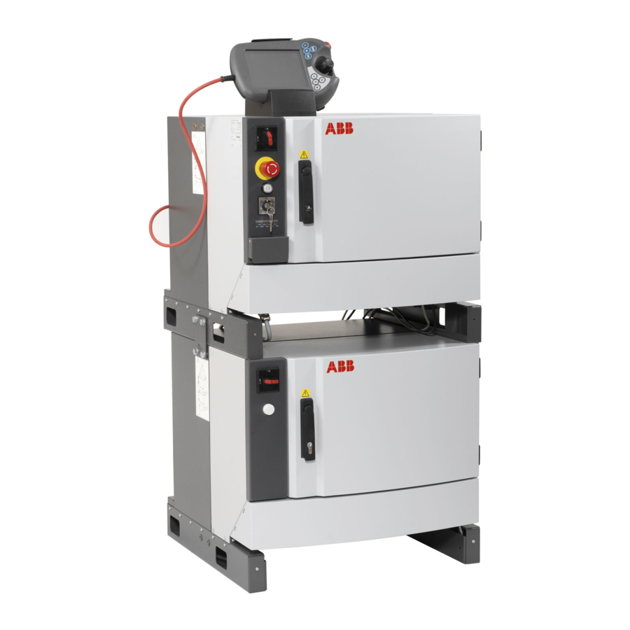
ABB IRC5 Operating Manual
Hide thumbs
Also See for IRC5:
- Operating manual (590 pages) ,
- Product manual (550 pages) ,
- Applications manual (110 pages)
Summary of Contents for ABB IRC5
- Page 1 ABB Robotics Operating manual Trouble shooting, IRC5...
- Page 3 Operating manual - Trouble shooting, IRC5 Robot Controller IRC5 M2004 Document ID: 3HAC020738-001 Revision: K...
- Page 4 Except as may be expressly stated anywhere in this manual, nothing herein shall be construed as any kind of guarantee or warranty by ABB for losses, damages to persons or property, fitness for a specific purpose or the like.
- Page 5 Table of Contents Overview of this manual..............5 1 Safety 1.1 Safety signals in the manual .
- Page 6 Table of Contents 5 Descriptions and background information 5.1 Indications............... . 69 5.1.1 LEDs in the Control Module .
- Page 7 Overview of this manual Overview of this manual About this manual This manual contains information, procedures and descriptions, for trouble shooting IRC5 based robot systems. Usage This manual should be used whenever robot operation is interrupted by malfunction, regardless of whether an error event log message is created or not.
- Page 8 Overview of this manual Continued Revisions Revision Description First edition. Information has been added. The document has been partly restructured. Information on how to submit error report has been changed. Information on RAPID change logs have been added. Event log messages have been added. Updated Event log messages.
- Page 9 1 Safety 1.1. Safety signals in the manual 1 Safety 1.1. Safety signals in the manual Introduction to safety signals This section specifies all dangers that can arise when doing the work described in this manual. Each danger consists of: •...
- Page 10 1 Safety 1.1. Safety signals in the manual Continued Symbol Designation Significance ELECTROSTATIC Warns for electrostatic hazards which could result in DISCHARGE (ESD) severe damage to the product. Electrostatic discharge (ESD) NOTE Describes important facts and conditions. Note Describes where to find additional information or how to do an operation in an easier way.
- Page 11 1 Safety 1.2. Safety symbols on the manipulator labels 1.2. Safety symbols on the manipulator labels Introduction to labels This section describes safety symbols used on labels (stickers) on the manipulator. Symbol are used in combinations on the labels, describing each specific warning. The descriptions in this section are generic, the labels can contain additional information such as values.
- Page 12 1 Safety 1.2. Safety symbols on the manipulator labels Continued Symbol Description Product manual Read the product manual for details. xx0900000813 Before dismantling see product manual xx0900000816 Do not dismantle Dismantling this part can cause injury. xx0900000815 Extended rotation This axis has extended rotation (working area) compared to standard.
- Page 13 1 Safety 1.2. Safety symbols on the manipulator labels Continued Symbol Description Heat Risk of heat that can cause burns. xx0900000818 Moving robot The robot can move unexpectedly. xx0900000819 Brake release buttons xx0900000820 Lifting bolt xx0900000821 Lifting of robot xx0900000822 Can be used in combination with prohibition if oil is not allowed.
- Page 14 1 Safety 1.2. Safety symbols on the manipulator labels Continued Symbol Description Mechanical stop xx0900000824 Stored energy Warns that this part contains stored energy. Used in combination with Do not dismantle symbol. xx0900000825 Pressure Warns that this part is pressurized. Usually contains additional text with the pressure level.
- Page 15 1 Safety 1.3. Safety during trouble shooting 1.3. Safety during trouble shooting General All normal service work; installation, maintenance and repair work, is usually performed with all electrical, pneumatic and hydraulic power switched off. All manipulator movements are usually prevented by mechanical stops etc. Trouble shooting work differs from this.
- Page 16 1 Safety 1.4. Applicable safety standards 1.4. Applicable safety standards Standards, EN ISO The manipulator system is designed in accordance with the requirements of: Standard Description EN ISO 12100 -1 Safety of machinery - Basic concepts, general principles for design - Part 1: Basic terminology, methodology EN ISO 12100 -2 Safety of machinery - Basic concepts, general principles for design - Part 2: Technical principles...
- Page 17 1 Safety 1.4. Applicable safety standards Continued Other standards Standard Description ANSI/RIA R15.06 Safety Requirements for Industrial Robots and Robot Systems ANSI/UL 1740 Safety Standard for Robots and Robotic Equipment (option 429-1) CAN/CSA Z 434-03 Industrial Robots and Robot Systems - General Safety Require- ments (option 429-1) 3HAC020738-001 Revision: K...
- Page 18 1 Safety 1.5.1. DANGER - Robot without axes' holding brakes are potentially lethal! 1.5 Safe Trouble Shooting 1.5.1. DANGER - Robot without axes' holding brakes are potentially lethal! Description Since the robot arm system is quite heavy, especially on larger robot models, it is dangerous if the holding brakes are disconnected, faulty, worn or in any way rendered non-operational.
- Page 19 1 Safety 1.5.2. DANGER - Live voltage inside Drive Module! 1.5.2. DANGER - Live voltage inside Drive Module! Description The Drive Module has live voltage potentially accessible directly behind the rear covers and inside the front cover, even when the main switches have been switched off. en1000000049 en1000000050 Live voltage at transformer terminals even if the main power switches have been...
- Page 20 1 Safety 1.5.2. DANGER - Live voltage inside Drive Module! Continued Elimination Read this information before opening the rear cover of either module. Step Action 1. Make sure the incoming mains power supply has been switched off. 2. Use a voltmeter to verify that there is not voltage between any of the terminals. 3.


