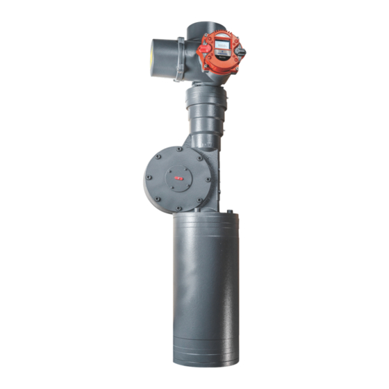
Emerson Bettis RTS Installation, Operation And Maintenance Manual
Hide thumbs
Also See for Bettis RTS:
- Installation, operation and maintenance manual (26 pages) ,
- Service manual (18 pages) ,
- Installation, operation and maintenance manual (18 pages)
Summary of Contents for Emerson Bettis RTS
- Page 1 Installation, Operation and Maintenance Manual VCIOM-15517-EN Rev. 0 July 2021 Bettis RTS Connectivity with Modbus TCP...
- Page 2 Notes Installation, Operation and Maintenance Manual July 2021 VCIOM-15517-EN Rev. 0 This page intentionally left blank...
-
Page 3: Table Of Contents
Installation, Operation and Maintenance Manual Table of Contents VCIOM-15517-EN Rev. 0 July 2021 Table of Contents Section 1: General General ........................1 Section 2: Topology Topology......................... 2 Section 3: Connection Connection ......................3 Section 4: Settings Settings ........................4 Section 5: Description of Input and Output Data Register Assignment for the Input Data (Data from Master to Slave) .... - Page 4 Notes Installation, Operation and Maintenance Manual July 2021 VCIOM-15517-EN Rev. 0 This page intentionally left blank...
-
Page 5: Section 1: General
A fieldbus interface for the Modbus TCP bus system is available for Emerson actuators in the Bettis RTS Series of Electric Actuators. Modbus TCP is an Ethernet-based fieldbus system. This interface is a hardware option and should already be known when ordering the actuator. -
Page 6: Section 2: Topology
Section 2: Topology Installation, Operation and Maintenance Manual July 2021 VCIOM-15517-EN Rev. 0 Section 2: Topology Since two ports are executed on the additional board for the Modbus TCP, the following network topologies can be implemented: • Line structure • Tree structure •... -
Page 7: Section 3: Connection
Installation, Operation and Maintenance Manual Section 3: Connection VCIOM-15517-EN Rev. 0 July 2021 Section 3: Connection The connection of the RTS Control Unit to the Modbus TCP is done at the field level because of the high degree of protection required via 4-pin, D-coded, M12 connectors (see IEC 61076-2-101). -
Page 8: Section 4: Settings
Section 4: Settings Installation, Operation and Maintenance Manual July 2021 VCIOM-15517-EN Rev. 0 Section 4: Settings The following additional parameters become visible in the control unit for the Bettis RTS electric actuator with the Modbus TCP option enabled. Table 2. Menu Sub-menu Poss. -
Page 9: Section 5: Description Of Input And Output Data
Installation, Operation and Maintenance Manual Section 5: Input and Output Data VCIOM-15517-EN Rev. 0 July 2021 Section 5: Description of Input and Output Data General information: Depending on the master, it is possible that the low byte (bits 0 - 7) and the high byte (bits 8 - 15) have to be swapped in the registry values. -
Page 10: Command
Section 5: Input and Output Data Installation, Operation and Maintenance Manual July 2021 VCIOM-15517-EN Rev. 0 5.1.2 Command Registry number: 1 Data format: 16-bit (bit field) Structure: Table 4. Description Function Bit=1 Bit= 0 OPEN OPEN command in REMOTE mode CLOSE CLOSE command in REMOTE mode STOP... -
Page 11: Command 2
Installation, Operation and Maintenance Manual Section 5: Input and Output Data VCIOM-15517-EN Rev. 0 July 2021 5.1.3 Command 2 Register number: 2 Data format: 16-bit (bit field) Structure: Table 5. Description Function Bit=1 Bit= 0 Bus Bit 1 Bus Bit 2 Bus Bit 3 These binary outputs can be assigned to the bus. -
Page 12: Modules For The Output Data (Slave To Master)
Section 5: Input and Output Data Installation, Operation and Maintenance Manual July 2021 VCIOM-15517-EN Rev. 0 Modules for the Output Data (Slave to Master) The register values can be read with function 4 (04 : Read input register). WARNING Depending on the master, the register numbers are assigned with an offset! For example, register 0 in the master has the address 1 or 40001 5.2.1... -
Page 13: Status
Installation, Operation and Maintenance Manual Section 5: Input and Output Data VCIOM-15517-EN Rev. 0 July 2021 5.2.2 Status Registry number: 1 Data format:16-bit (bit field) Structure: Table 8. Description Function Bit= 0 Bit=1 READY Actuator is ready End position OPEN reached (taking into account the type of END POSITION OPEN de-activation (torque- or travel-dependent)) END POSITION... -
Page 14: Actual Speed
Section 5: Input and Output Data Installation, Operation and Maintenance Manual July 2021 VCIOM-15517-EN Rev. 0 5.2.4 Actual Speed Registry number: 3 Data format: 16-bit, only the lower 8 bits (Bit 7: in direction OPEN; bit 6 - 0: 0 - 100 corresponding to 0 - 100%) are used. -
Page 15: Status 3
Installation, Operation and Maintenance Manual Section 5: Input and Output Data VCIOM-15517-EN Rev. 0 July 2021 5.2.7 Status 3 Record Number: 6 Data format: 16-bit, error number Table 10. Error number Meaning Motor temperature warning Motor temperature cut-out Phase sequence error or phase loss Error in the power supply or the frequency converter Error in the fail-safe unit (provided there is one) Fault position sensor... - Page 16 P. R. China Székesfehérvár 8000 T +86 22 8212 3300 Hungary The Emerson logo is a trademark and service mark of Emerson Electric Co. T +36 22 53 09 50 Bettis is a mark of one of the Emerson family of companies.


