Fujitsu AUXG07KVLA Service Manual
Hide thumbs
Also See for AUXG07KVLA:
- Manual (403 pages) ,
- Design & technical manual (296 pages) ,
- Service manual (125 pages)
Table of Contents
Quick Links
AIR CONDITIONER
4-unit multi-split type,
5-unit multi-split type
INDOOR
ASHG07–14KGTB
ASHG07–14KETA-B
ASHG07–14KETE-B
SERVICE MANUAL
AUXG07–22KVLA
ARXG07–14KSLAP
ASHG07–14KGTE
ASHG18–24KMTB
ASHG18–24KMTE
ABHG18–22KRTA AGHG09–14KVCA
ARXG07–14KLLAP
ARXG18KSLAP
ARXG18KLLAP
ASHG07–14KMTB
ASHG07–14KMCC
ASHG07–14KMCE
OUTDOOR
ARXG22KMLB
ASHG07–14KETA
ASHG07–14KETE
AOHG30KBTA4
AOHG36KBTA5
SR_MU004EG_13
2022.08.08
Chapters
Table of Contents
Troubleshooting

Related Manuals for Fujitsu AUXG07KVLA


Summary of Contents for Fujitsu AUXG07KVLA
- Page 1 AIR CONDITIONER 4-unit multi-split type, 5-unit multi-split type SERVICE MANUAL INDOOR AUXG07–22KVLA ARXG07–14KSLAP ARXG07–14KLLAP ARXG22KMLB ARXG18KSLAP ARXG18KLLAP ASHG07–14KGTB ASHG07–14KGTE ASHG18–24KMTB ASHG07–14KMTB ASHG07–14KETA ASHG18–24KMTE ASHG07–14KMCC ASHG07–14KETE ASHG07–14KMCE OUTDOOR ASHG07–14KETA-B ABHG18–22KRTA AGHG09–14KVCA AOHG30KBTA4 ASHG07–14KETE-B AOHG36KBTA5 SR_MU004EG_13 2022.08.08...
- Page 2 • Product specifications and design are subject to change without notice for future improvement. • For further details, please check with our authorized dealer. Trademarks ™ FGLair is trademark of Fujitsu General Limited in the United States, other countries or both. ™ Google Play is trademark of Google LLC. ®...
- Page 3 CONTENTS 1. GENERAL INFORMATION 2. TECHNICAL DATA AND PARTS LIST 3. TROUBLESHOOTING 4. CONTROL AND FUNCTIONS 5. FILED WORKING...
- Page 5 1. GENERAL INFORMATION 2022.08.08 SR_CH01_MU004EG_06...
- Page 6 CONTENTS 1. GENERAL INFORMATION 1. Specifications....................01-1 1-1. Indoor unit ........................01-1 1-2. Outdoor unit........................01-19 2. Dimensions....................01-23 2-1. Compact cassette type ....................01-23 2-2. Mini duct type .......................01-25 2-3. Slim duct type .......................01-28 2-4. Medium static pressure duct type .................01-31 2-5. Wall mounted type......................01-33 2-6.
- Page 7 1. Specifications 1-1. Indoor unit ¢ Compact cassette type Model name AUXG07KVLA AUXG09KVLA AUXG12KVLA AUXG14KVLA Power supply 1Ø 230 V ~50 Hz Available voltage range 198—264 V Capacity kW class Input power Running current 0.15 0.19 0.22 HIGH Cooling QUIET...
- Page 8 Model name AUXG18KVLA AUXG22KVLA Power supply 1Ø 230 V ~50 Hz Available voltage range 198—264 V Capacity kW class Input power Running current 0.30 0.62 HIGH Cooling QUIET Airflow rate HIGH Heating QUIET Type × Q'ty Turbo fan × 1 Motor output HIGH Cooling...
- Page 9 ¢ Mini duct type Model name ARXG07KSLAP ARXG09KSLAP ARXG12KSLAP ARXG14KSLAP Power supply 1Ø 230 V ~50 Hz Available voltage range 198—264 V Capacity kW class HIGH Input power QUIET Running current 0.29 0.33 0.38 0.58 HIGH Cooling QUIET Airflow rate HIGH Heating QUIET...
- Page 10 Model name ARXG18KSLAP Power supply 1Ø 230 V ~ 50 Hz Available voltage range 198—264 V Capacity kW class HIGH Input power QUIET Running current 0.49 HIGH Cooling QUIET Airflow rate HIGH Heating QUIET Type × Q'ty Sirocco fan × 3 Motor output Recommended static pressure 0 to 50...
- Page 11 ¢ Slim duct type Model name ARXG07KLLAP ARXG09KLLAP ARXG12KLLAP ARXG14KLLAP Power supply 1Ø 230 V ~50 Hz Available voltage range 198—264 V Capacity kW class Input power Running current 0.33 0.30 0.35 0.51 HIGH Cooling QUIET Airflow rate HIGH Heating QUIET Type ×...
- Page 12 Model name ARXG18KLLAP Power supply 1Ø 230 V ~50 Hz Available voltage range 198—264 V Capacity kW class Input power Running current 0.44 HIGH Cooling QUIET Airflow rate HIGH Heating QUIET Type × Q'ty Sirocco fan × 3 Motor output Recommended static pressure 0 to 90 HIGH...
- Page 13 ¢ Medium static pressure duct type Model name ARXG22KMLB Power supply 1Ø 230 V ~50 Hz Available voltage range 198—264 V Capacity kW class Input power Running current 0.60 HIGH 1,100 Cooling QUIET Airflow rate HIGH 1,100 Heating QUIET Type × Q'ty Sirocco fan ×...
- Page 14 ¢ Wall mounted type Model name ASHG07KGTB ASHG09KGTB ASHG12KGTB ASHG14KGTB Power supply 1Ø 230 V ~50 Hz Available voltage range 198—264 V Capacity kW class Input power Running current 0.20 0.24 0.24 0.29 HIGH Cooling QUIET Airflow rate HIGH Heating QUIET Type ×...
- Page 15 Model name ASHG07KGTE ASHG09KGTE ASHG12KGTE ASHG14KGTE Power supply 1Ø 230 V ~50 Hz Available voltage range 198—264 V Capacity kW class Input power Running current 0.20 0.24 0.24 0.29 HIGH Cooling QUIET Airflow rate HIGH Heating QUIET Type × Q'ty Crossflow fan ×...
- Page 16 Model name ASHG18KMTB ASHG22KMTB ASHG24KMTB Power supply 1Ø 230 V ~50 Hz Available voltage range 198—264 V Capacity kW class Input power 37.5 47.0 61.6 Running current 0.35 0.39 0.44 HIGH 1,060 1,170 Cooling QUIET Airflow rate HIGH 1,020 1,060 1,170 Heating QUIET...
- Page 17 Model name ASHG18KMTE ASHG22KMTE ASHG24KMTE Power supply 1Ø 230 V ~50 Hz Available voltage range 198—264 V Capacity kW class Input power 37.5 47.0 61.6 Running current 0.35 0.39 0.44 HIGH 1,060 1,170 Cooling QUIET Airflow rate HIGH 1,020 1,060 1,170 Heating QUIET...
- Page 18 Model name ASHG07KMTB ASHG09KMTB ASHG12KMTB ASHG14KMTB Power supply 1Ø 230 V ~50 Hz Available voltage range 198—264 V Capacity kW class Input power Running current 0.20 0.24 0.24 0.30 HIGH Cooling QUIET Airflow rate HIGH Heating QUIET Type × Q'ty Crossflow fan ×...
- Page 19 Model name ASHG07KMCC ASHG09KMCC ASHG12KMCC ASHG14KMCC Power supply 1Ø 230 V ~50 Hz Available voltage range 198—264 V Capacity kW class Input power Running current 0.20 0.24 0.24 0.30 HIGH Cooling QUIET Airflow rate HIGH Heating QUIET Type × Q'ty Crossflow fan ×...
- Page 20 Model name ASHG07KMCE ASHG09KMCE ASHG12KMCE ASHG14KMCE Power supply 1Ø 230 V ~50 Hz Available voltage range 198—264 V Capacity kW class Input power Running current 0.20 0.24 0.24 0.30 HIGH Cooling QUIET Airflow rate HIGH Heating QUIET Type × Q'ty Crossflow fan ×...
- Page 21 ASHG07KETA ASHG09KETA ASHG12KETA ASHG14KETA Model name ASHG07KETA-B ASHG09KETA-B ASHG12KETA-B ASHG14KETA-B Power supply 1Ø 230 V ~50 Hz Available voltage range 198—264 V Capacity kW class Input power Running current 0.20 0.24 0.24 0.30 HIGH Cooling QUIET Airflow rate HIGH Heating QUIET Type ×...
- Page 22 ASHG07KETE ASHG09KETE ASHG12KETE ASHG14KETE Model name ASHG07KETE-B ASHG09KETE-B ASHG12KETE-B ASHG14KETE-B Power supply 1Ø 230 V ~50 Hz Available voltage range 198—264 V Capacity kW class Input power Running current 0.20 0.24 0.24 0.30 HIGH Cooling QUIET Airflow rate HIGH Heating QUIET Type ×...
- Page 23 ¢ Ceiling type Model name ABHG18KRTA ABHG22KRTA Power supply 1Ø 230 V ~50 Hz Available voltage range 198—264 V Capacity kW class Input power Running current 0.21 0.25 HIGH Cooling QUIET Airflow rate HIGH Heating QUIET Type × Q'ty Sirocco × 2 Motor output HIGH Cooling...
- Page 24 ¢ Floor type Model name AGHG09KVCA AGHG12KVCA AGHG14KVCA Power supply 230 V ~ 50 Hz Available voltage range 198—264 V Capacity kW class Input power Running current 0.15 0.18 0.20 HIGH Cooling QUIET Airflow rate HIGH Heating QUIET Type × Q'ty Cross flow fan ×...
- Page 25 1-2. Outdoor unit ¢ Model: AOHG30KBTA4 Type Inverter heat pump Model name AOHG30KBTA4 Power source 230 V 50 Hz Available voltage range 198—264V Wall mounted Standard combination of indoor unit ASHG07KMCC ×4 Rated Btu/h 27,300 Cooling 2.4—10.1 Min.—Max. Btu/h 8,200—34,500 Capacity Rated Btu/h...
- Page 26 Specifications for ErP Lot10 Model name AOHG30KBTA4 Cooling Energy efficiency class Heating (Average) Cooling 8.0 (35 °C) Pdesign Heating (Average) 6.5 (-10 °C) SEER Cooling 8.50 kWh/kWh SCOP Heating (Average) 4.60 Annual energy consumption kWh/a QHE (Average) 1,978 Cooling Sound power level HIGH dB (A) Heating...
- Page 27 ¢ Model: AOHG36KBTA5 Type Inverter heat pump Model name AOHG36KBTA5 Power source 230 V 50 Hz Available voltage range 198—264V Wall mounted Standard combination of indoor unit ASHG07KMCC ×5 Rated Btu/h 32,400 Cooling 3.0—11.0 Min.—Max. Btu/h 10,200—37,500 Capacity 10.6 Rated Btu/h 36,200 Heating...
- Page 28 Specifications for ErP Lot10 Model name AOHG36KBTA5 Cooling Energy efficiency class Heating (Average) Cooling 9.5 (35 °C) Pdesign Heating (Average) 7.0 (-10 °C) SEER Cooling 8.50 kWh/kWh SCOP Heating (Average) 4.60 Annual energy consumption kWh/a QHE (Average) 2,130 Cooling Sound power level HIGH dB (A) Heating...
- Page 29 2. Dimensions 2-1. Compact cassette type ¢ Models: AUXG07KVLA, AUXG09KVLA, AUXG12KVLA, AUXG14KVLA, AUXG18KVLA, and AUXG22KVLA Unit: mm Grid type grille Hanging bolt position IR receiver Drain hose View A Ceiling Control Box View C View B - (01-23) - 2-1. Compact cassette type...
- Page 30 Installation space requirement Unit: mm Strong and durable ceiling or more 1,000 1,000 or more or more 1,800 or more Obstruction Floor Maximum height from floor to ceiling (Unit: mm) 07 and 09 models 12 or larger models Standard 2,700 High ceiling —...
- Page 31 2-2. Mini duct type ¢ Models: ARXG07KSLAP, ARXG09KSLAP, ARXG12KSLAP, and ARXG14KSLAP Unit: mm Rear view View A Drain port P 100 × 6 = 600 Top view Side view Front view Bottom view - (01-25) - 2-2. Mini duct type 2.
- Page 32 ¢ Model: ARXG18KSLAP Unit: mm Rear view View A Drain port P 100 × 8 = 800 Top view Side view Front view Bottom view - (01-26) - 2-2. Mini duct type 2. Dimensions...
- Page 33 Installation space requirement Provide sufficient installation space for product safety. Unit: mm Strong and durable ceiling Indoor unit Left Right side side or more* or more *: 400 or more when drain from drain pipe • When intaking air from back: •...
- Page 34 2-3. Slim duct type ¢ Models: ARXG07KLLAP, ARXG09KLLAP, ARXG12KLLAP, and ARXG14KLLAP Unit: mm View A Rear view Drain port 100 x 6 = 600 Side view Top view Front view Bottom view - (01-28) - 2-3. Slim duct type 2. Dimensions...
- Page 35 ¢ Model: ARXG18KLLAP Unit: mm Rear view View A Drain port 100 × 8 = 800 Top view Side view Front view Bottom view - (01-29) - 2-3. Slim duct type 2. Dimensions...
- Page 36 Installation space requirement Provide sufficient installation space for product safety. In ceiling-concealed installations: Unit: mm 300 or more Strong and durable ceiling 20 or more Indoor unit Left Right side side 20 or more Service access Ceiling or more or more Floor ...
- Page 37 2-4. Medium static pressure duct type ¢ Model: ARXG22KMLB Unit: mm Φ205 Φ3.2 Front view 1,177 Gas pipe Drain port Liquid pipe Φ200 Knockout Drain port for fresh air Φ5 Φ3.2 80 80 P125 × 3 = 375 P125 × 3 = 375 Φ5 1,015 1,135...
- Page 38 Maintenance space requirement Unit: mm • Provide a maintenance access for maintenance purposes. Maintenance access Control box • The maintenance access necessary for fan units and filter maintenance. Maintenance access Intake panel Control box 1,550 • When using a square duct P174 ×...
- Page 39 2-5. Wall mounted type ¢ Models: ASHG07KGTB, ASHG09KGTB, ASHG12KGTB, and ASHG14KGTB Unit: mm (834) Outline of indoor unit for pipe inlet Ø65 for pipe inlet Ø65 - (01-33) - 2-5. Wall mounted type 2. Dimensions...
- Page 40 Installation space requirement Provide sufficient installation space for product safety. Unit: mm 70 or more 40 or more Wall hook bracket Outline of the indoor unit 107 or more 183 or more 1,500 or more A: Install so that the flare connection part is outdoors. - (01-34) - 2-5.
- Page 41 ¢ Models: ASHG07KGTE, ASHG09KGTE, ASHG12KGTE, and ASHG14KGTE 373.5 417.5 (834) Outline of indoor unit for pipe inlet Ø65 for pipe inlet Ø65 - (01-35) - 2-5. Wall mounted type 2. Dimensions...
- Page 42 Installation space requirement Provide sufficient installation space for product safety. Unit: mm 40 or more 70 or more Wall hook bracket 107 or more 183 or more Outline of the indoor unit 1,500 or more A: Install so that the flare connection part is outdoors. - (01-36) - 2-5.
- Page 43 ¢ Models: ASHG18KMTB, ASHG22KMTB, and ASHG24KMTB Unit: mm Outline of indoor unit for pipe inlet Ø65 for pipe inlet Ø65 - (01-37) - 2-5. Wall mounted type 2. Dimensions...
- Page 44 Installation space requirement Provide sufficient installation space for product safety. Unit: mm 40 or more Wall hook bracket 70 or more Outline of the indoor unit 160 or more 117 or more 1,500 or more A: Install so that the flare connection part is outdoors. - (01-38) - 2-5.
- Page 45 ¢ Models: ASHG18KMTE, ASHG22KMTE, and ASHG24KMTE Unit: mm Outline of indoor unit for pipe inlet Ø65 for pipe inlet Ø65 - (01-39) - 2-5. Wall mounted type 2. Dimensions...
- Page 46 Installation space requirement Provide sufficient installation space for product safety. Unit: mm 40 or more Wall hook bracket 70 or more 117 or more Outline of the indoor unit 160 or more 1,500 or more The flare connection part should be installed outdoors.
- Page 47 ¢ Models: ASHG07KMTB, ASHG09KMTB, ASHG12KMTB, ASHG14KMTB, ASHG07KMCC, ASHG09KMCC, ASHG12KMCC, and ASHG14KMCC Unit: mm (834) Outline of indoor unit for pipe inlet Ø65 for pipe inlet Ø65 - (01-41) - 2-5. Wall mounted type 2. Dimensions...
- Page 48 Installation space requirement Provide sufficient installation space for product safety. Unit: mm 70 or more 40 or more Wall hook bracket Outline of the indoor unit 107 or more 183 or more 1,500 or more A: Install so that the flare connection part is outdoors. - (01-42) - 2-5.
- Page 49 ¢ Models: ASHG07KMCE, ASHG09KMCE, ASHG12KMCE, and ASHG14KMCE Unit: mm Outline of indoor unit for pipe inlet Ø65 for pipe inlet Ø65 - (01-43) - 2-5. Wall mounted type 2. Dimensions...
- Page 50 Installation space requirement Provide sufficient installation space for product safety. Unit: mm 40 or more 70 or more Wall hook bracket 107 or more 183 or more Outline of the indoor unit 1,500 or more A: Install so that the flare connection part is outdoors. - (01-44) - 2-5.
- Page 51 ¢ Models: ASHG07KETA, ASHG09KETA, ASHG12KETA, ASHG14KETA, ASHG07KETA-B, ASHG09KETA-B, ASHG12KETA-B, ASHG14KETA-B, ASHG07KETE, ASHG09KETE, ASHG12KETE, ASHG14KETE, ASHG07KETE-B, ASHG09KETE-B, ASHG12KETE-B, and ASHG14KETE-B Unit: mm 373.5 417.5 (950) Outline of indoor unit for pipe inlet Ø65 for pipe inlet Ø65 - (01-45) - 2-5. Wall mounted type 2.
- Page 52 Installation space requirement Provide sufficient installation space for product safety. Unit: mm 40 or more 40 or more Wall hook bracket Outline of the indoor unit 166 or more 211 or more 1,500 or more The flare connection part should be installed outdoors.
- Page 53 2-6. Ceiling type ¢ Models: ABHG18KRTA and ABHG22KRTA Unit: mm 1,080 49 84 125 103 Side view Top view ø100-mm hole Rear view Suspension bolt pitch Dimensions Indoor unit (Top view) (Space required for installation) The length of the bolt here is 30 mm.
- Page 54 ¢ Installation space requirement Unit: mm Ceiling Indoor unit 30 or more Ceiling 200 or more 0 or more Obstruction Floor Required ceiling height varies according to the ceiling mode setting of function setting No. 20. Ceiling height (m) Ceiling mode Standard High ceiling 18, 22 models...
- Page 55 2-7. Floor type ¢ Models: AGHG09KVCA, AGHG12KVCA, and AGHG14KVCA Unit: mm Side view Front view - (01-49) - 2-7. Floor type 2. Dimensions...
- Page 56 Installation space Unit: mm 100 or more 80 or more 80 or more 50 or more 150 or below from the floor PROHIBITED Grating WARNING • The appliance shall be installed, operated and stored in a room with a floor area larger than X Minimum room area Amount of refrigerant charge M (kg)
- Page 57 2-8. Outdoor unit ¢ Model: AOHG30KBTA4 Unit: mm 4-M10 hole Pitch of bolts for installation Top view Side view Front view Side view Airflow Drain port Ø42 Bottom view Side view (Valve part) - (01-51) - 2-8. Outdoor unit 2. Dimensions...
- Page 58 ¢ Model: AOHG36KBTA5 Unit: mm 4-M10 hole Pitch of bolts for installation Top view Side view Front view Side view Airflow Drain port Ø42 Bottom view Side view (Valve part) - (01-52) - 2-8. Outdoor unit 2. Dimensions...
- Page 59 2. TECHNICAL DATA AND PARTS LIST 2022.08.08 SR_CH02_MU004EG_11...
- Page 60 8-2. Mini duct type and Slim duct type ................02-118 8-3. Medium static pressure duct type ................02-119 8-4. Wall mounted type......................02-120 8-5. Ceiling type.........................02-129 8-6. Floor type ........................02-130 8-7. Outdoor unit........................02-131 9. PC board diagrams .................02-133 9-1. Models: AUXG07KVLA, AUXG09KVLA, AUXG12KVLA, AUXG14KVLA, AUXG18KVLA, and AUXG22KVLA......................02-133...
- Page 61 CONTENTS (continued) 9-2. Models: ARXG07KSLAP, ARXG09KSLAP, ARXG12KSLAP, ARXG14KSLAP, and ARXG18KSLAP ......................02-134 9-3. Models: ARXG07KLLAP, ARXG09KLLAP, ARXG12KLLAP, ARXG14KLLAP, and ARXG18KLLAP......................02-135 9-4. Model: ARXG22KMLB....................02-136 9-5. Models: ASHG07KGTB, ASHG09KGTB, ASHG12KGTB, and ASHG14KGTB..02-137 9-6. Models: ASHG07KGTE, ASHG09KGTE, ASHG12KGTE, and ASHG14KGTE..02-138 9-7. Models: ASHG18KMTB, ASHG22KMTB, and ASHG24KMTB........02-139 9-8.
- Page 63 • Service parts information and design are subject to change without notice for product improve- ment. • For the latest information of the service parts, refer to our Service Portal. https://fujitsu-general.force.com/portal/ • Precise figure of the service parts listed in this manual may differ from the actual service parts. - (02-1) -...
- Page 64 2. Cassette grille (optional part) parts list 2-1. Model: UTG-UFGF-W ¢ Overall - (02-2) - 2-1. Model: UTG-UFGF-W 2. Cassette grille (optional part) parts list...
- Page 65 Item no. Part no. Part name Service part 9377760043 Flap total assy ♦ 9377759047 Flap assy B ♦ 9375727048 Flap assy A ♦ 9375539016 Joint B ♦ 9375540012 Joint shaft ♦ 9375746018 Motor holder assy B ♦ 9900139087 Step motor (with Red connector) ♦...
- Page 66 3. Indoor unit parts list 3-1. Compact cassette type ¢ Models: AUXG07KVLA, AUXG09KVLA, AUXG12KVLA, AUXG14KVLA, AUXG18KVLA, and AUXG22KVLA Item no. Part no. Part name Service part 9379665001 Drain hose ♦ 9379757010 Hose band ♦ 9900942038 Pipe thermistor ♦ 9900826000 Room thermistor ♦...
- Page 67 Item no. Part no. Part name Service part 9710995965 Main PCB (For 07 model) ♦ 9710995743 Main PCB (For 09 model) ♦ 9710995750 Main PCB (For 12 model) ♦ 9710995705 Main PCB (For 14 model) ♦ 9710995767 Main PCB (For 18 model) ♦...
- Page 68 Wire holder Item no. Part no. Part name Service part 9375516017 Wire cover ♦ 9375515010 Pipe cover ♦ 9375503017 Bell-mouth hood ♦ 9375477011 Thermistor holder ♦ 9377765024 Drain pan sub assy (For 18 model) ♦ 9377765017 Drain pan sub assy (For 22 model) ♦...
- Page 69 Separate wall Evaporator holder 2 row Item no. Part no. Part name Service part 9375720254 Evaporator sub assy (For 07 model) ♦ 9375720230 Evaporator sub assy (For 09, 12 model) ♦ 9375720223 Evaporator sub assy (For 14 model) ♦ 9375720247 Evaporator sub assy (For 18 model) ♦...
- Page 70 Top plate assy Motor wire holder Cabinet A sub assy Cabinet B sub assy Turbo fan washer Item no. Part no. Part name Service part 9375719012 Fan motor sub assy ♦ 9602436019 Fan motor ♦ 9375480011 2 stage turbo fan assy ♦...
- Page 71 3-2. Mini duct type ¢ Models: ARXG07KSLAP, ARXG09KSLAP, ARXG12KSLAP, and ARXG14KSLAP Item no. Part no. Part name Service part 9710661020 Power supply PCB ♦ 9710624261 Main PCB (For 07 model) ♦ 9710624278 Main PCB (For 09 model) ♦ 9710624285 Main PCB (For 12 model) ♦...
- Page 72 Main Panel (2 Fan) Item no. Part no. Part name Service part 9381930111 Drain pan sub assy ♦ 9381933440 Evaporator total assy ♦ 9900472061 Pump assy ♦ 9900465063 Float switch ♦ 9378450097 Hose sub assy ♦ - (02-10) - 3-2. Mini duct type 3.
- Page 73 Item no. Part no. Part name Service part 9379570015 Sirocco fan assy ♦ 9381673001 Rubber (Vibration proof) ♦ 9381676002 Casing B ♦ 9381677016 Casing U ♦ 9380636038 Fan motor assy (For 07 model) ♦ 9379574006 Air filter ♦ 9381675005 Motor bracket assy ♦...
- Page 74 ¢ Model: ARXG18KSLAP Chassis - (02-12) - 3-2. Mini duct type 3. Indoor unit parts list...
- Page 75 Item no. Part no. Part name Service part 9379971065 Sirroco fan sub assy ♦ 9383443008 Rubber vibration proof assy ♦ 9379570022 Sirroco fan assy ♦ 9381676002 Casing B ♦ 9379047128 Motor band L ♦ 9381669004 Motor band L ♦ 9381670000 Motor band R ♦...
- Page 76 Inverter unit - (02-14) - 3-2. Mini duct type 3. Indoor unit parts list...
- Page 77 Item no. Part no. Part name Service part 9710624315 Main PCB ♦ 9710019005 2way remote PCB ♦ 9900896003 Terminal (remote control) ♦ 9900568009 Terminal (power) ♦ 9710661020 Power PCB ♦ Wire with connector — 9710177057 ♦ (CN46—External input) Wire with connector —...
- Page 78 3-3. Slim duct type ¢ Models: ARXG07KLLAP, ARXG09KLLAP, ARXG12KLLAP, and ARXG14KLLAP Item no. Part no. Part name Service part 9379906012 Side panel R sub assy ♦ 9379907019 Side panel L sub assy ♦ 9379900003 Pipe panel sub assy ♦ 9379915007 Panel (Window) sub assy ♦...
- Page 79 Item no. Part no. Part name Service part 9379908030 Total panel sub assy ♦ 9379570015 Sirocco fan assy ♦ 9379644006 Rubber (Vibration proof) ♦ 9379572019 Casing B ♦ 9379571012 Casing U ♦ 9379047166 Fan motor assy (For 07 model) ♦ 9379047159 Fan motor assy (For 09, 12, 14 model) ♦...
- Page 80 Item no. Part no. Part name Service part 9710661006 Power supply PCB ♦ 9710624308 Main PCB (For 07 model) ♦ 9710624209 Main PCB (For 09 model) ♦ 9710624216 Main PCB (For 12 model) ♦ 9710624148 Main PCB (For 14 model) ♦...
- Page 81 ¢ Model: ARXG18KLLAP Item no. Part no. Part name Service part 9379906012 Side panel R sub assy ♦ 9379907019 Side panel L sub assy ♦ 9379900003 Pipe panel sub assy ♦ 9379915007 Panel (Window) sub assy ♦ 9380042013 Outlet frame assy ♦...
- Page 82 Item no. Part no. Part name Service part 9379908047 Total panel sub assy ♦ 9379570022 Sirocco fan assy ♦ 9379570039 Sirocco fan assy ♦ 9381052004 Shaft assy ♦ 9378038011 Joint assy ♦ 9379644006 Rubber (Vibration proof) ♦ 9379572019 Casing B ♦...
- Page 83 Item no. Part no. Part name Service part 9710661006 Power supply PCB ♦ 9710624131 Main PCB ♦ 9710019005 2-way remote PCB ♦ 9900568009 Terminal 3P ♦ 9900896003 Terminal 3P (For wired remote controller) ♦ — 9900653019 Room thermistor ♦ — 9900942045 Pipe thermistor ♦...
- Page 84 3-4. Medium static pressure duct type ¢ Model: ARXG22KMLB Hook metal Item no. Part no. Part name Service part 9900826048 Room thermistor ♦ 9900942045 Pipe thermistor ♦ - (02-22) - 3-4. Medium static pressure duct type 3. Indoor unit parts list...
- Page 85 Item no. Part no. Part name Service part 9710624322 Main PCB ♦ 0600063023 Holder ♦ 9710019005 Communication PCB ♦ 9710661013 Power supply PCB ♦ 9306489045 Terminal 3P ♦ 9900896003 Terminal 5P ♦ 9707457049 Reactor assy ♦ - (02-23) - 3-4. Medium static pressure duct type 3.
- Page 86 Main panel sub assy Bracket pipe sub assy Item no. Part no. Part name Service part 9374513017 Drain pan sub assy ♦ 9374517978 Evaporator total assy ♦ - (02-24) - 3-4. Medium static pressure duct type 3. Indoor unit parts list...
- Page 87 Intake cover sub assy Intake frame assy Motor bracket Item no. Part no. Part name Service part 9374233021 Casing A ♦ 9374234028 Casing B ♦ 9356531060 Sirocco fan assy ♦ 9380718031 Fan motor assy ♦ 9385102002 Rubber ♦ - (02-25) - 3-4.
- Page 88 3-5. Wall mounted type ¢ Models: ASHG07KGTB, ASHG09KGTB, ASHG12KGTB, and ASHG14KGTB Exterior parts and chassis Item no. Part no. Part name Service part 9382108045 Remote control ♦ 9318912005 Remote control holder ♦ 9387480009 Bracket panel ♦ 9332911008 Electric filter holder ♦...
- Page 89 Wire cover assy Item no. Part no. Part name Service part 9387476002 Screw cover ♦ 9387477009 Under cover L ♦ 9387478006 Under cover R ♦ 9387596007 Front panel total assy ♦ - (02-27) - 3-5. Wall mounted type 3. Indoor unit parts list...
- Page 90 Front panel Frontpanel cover Panel cover Front panel B Item no. Part no. Part name Service part 9387473001 Air filter ♦ 9387756005 Intake grille assy ♦ 9333719009 Grille clamper L ♦ 9333704005 Grille clamper R ♦ - (02-28) - 3-5. Wall mounted type 3.
- Page 91 Item no. Part no. Part name Service part 9387479003 Horizontal louver assy ♦ 9332861006 Shaft cover ♦ 9387471007 Louver spring ♦ - (02-29) - 3-5. Wall mounted type 3. Indoor unit parts list...
- Page 92 Control cover Item no. Part no. Part name Service part 9387467000 Room Thermistor Holder ♦ 9900627041 Thermistor Assy ♦ - (02-30) - 3-5. Wall mounted type 3. Indoor unit parts list...
- Page 93 Control box WLAN holder holder A Box shield Control box Display case assy Front panel cover B assy Item no. Part no. Part name Service part 9710782411 Main PCB (for 07 model) ♦ 9710782428 Main PCB (for 09 model) ♦...
- Page 94 Evaporator Motor case Motor cover assy Step motor holder assy Cable guide Step motor holder Item no. Part no. Part name Service part 9387593143 Evaporator total assy (for 07, 09, 12 model) ♦ 9387593150 Evaporator total assy (for 14 model) ♦...
- Page 95 ¢ Models: ASHG07KGTE, ASHG09KGTE, ASHG12KGTE, and ASHG14KGTE Exterior parts - (02-33) - 3-5. Wall mounted type 3. Indoor unit parts list...
- Page 96 Item no. Part no. Part name Service part 9388142005 Bracket panel ♦ 9383729027 Wire cover B assy ♦ 9387456004 Step motor holder ♦ 9333608006 Bush ♦ 9901011047 Step motor ♦ 9332861006 Shaft cover ♦ 9387590241 Drain pan total assy ♦ 9387476002 Screw cover ♦...
- Page 97 Base, evaporator, and control - (02-35) - 3-5. Wall mounted type 3. Indoor unit parts list...
- Page 98 Item no. Part no. Part name Service part 9387587128 Base assy ♦ 9388139005 Pipe bracket A ♦ 9388138008 Under cover C ♦ 9388182001 Screw cover ♦ 9383765056 WLAN adapter holder assy ♦ 9711732255 Main PCB (For 07 model) ♦ 9711732262 Main PCB (For 09 model) ♦...
- Page 99 ¢ Models: ASHG18KMTB, ASHG22KMTB, and ASHG24KMTB Item no. Part no. Part name Service part 9383712012 Remote controller ♦ 9318912005 Remote controller holder ♦ 9323351004 Bracket panel ♦ 9332911008 Electric filter holder ♦ 9317250009 Air clean filter assy ♦ - (02-37) - 3-5.
- Page 100 Item no. Part no. Part name Service part 9387476002 Screw cover ♦ 9323341012 Under cover L ♦ 9323342019 Under cover R ♦ 9387596625 Front panel total assy ♦ - (02-38) - 3-5. Wall mounted type 3. Indoor unit parts list...
- Page 101 Front panel total assy Front panel B Front panel Panel cover Item no. Part no. Part name Service part 9323340008 Air filter ♦ 9387756111 Intake grille assy ♦ 9333719009 Grille clamper L ♦ 9333704005 Grille clamper R ♦ - (02-39) - 3-5.
- Page 102 Wire cover B assy Wire cover assy Item no. Part no. Part name Service part 9387479010 Horizontal louver assy ♦ 9383730030 Louver spring ♦ - (02-40) - 3-5. Wall mounted type 3. Indoor unit parts list...
- Page 103 Wifi holder assy Control cover Item no. Part no. Part name Service part 9387467000 Room thermistor holder ♦ 9900627041 Thermistor assy ♦ - (02-41) - 3-5. Wall mounted type 3. Indoor unit parts list...
- Page 104 Control box Display case assy Item no. Part no. Part name Service part 9711141538 Main PCB (For 18 model) ♦ 9711141545 Main PCB (For 22 model) ♦ 9711141552 Main PCB (For 24 model) ♦ 9306489045 Terminal ♦ 9711146052 Display assy ♦...
- Page 105 Item no. Part no. Part name Service part 9383735011 Evaporator total assy ♦ - (02-43) - 3-5. Wall mounted type 3. Indoor unit parts list...
- Page 106 Base total assy Motor cover assy Fan motor Base assy Pipe bracket Motor case Motor cover assy Item no. Part no. Part name Service part 9603631000 Brushless motor ♦ 9387055054 Crossflow fan assy ♦ 9333628004 Bearing D assy ♦ - (02-44) - 3-5.
- Page 107 Cable guide Drain pan total assy Vertical louver stepping motor assy Gear case assy Gear case assy Specer K assy Vertical louver stepping motor assy Item no. Part no. Part name Service part 9387590142 Drain pan total assy ♦ 9901011016 Stepping motor ♦...
- Page 108 ¢ Models: ASHG18KMTE, ASHG22KMTE, and ASHG24KMTE Exterior parts - (02-46) - 3-5. Wall mounted type 3. Indoor unit parts list...
- Page 109 Item no. Part no. Part name Service part 9388158013 Bracket panel ♦ 9387476002 Screw cover ♦ 9383729027 Wire cover assy B ♦ 9387597066 Wire cover assy ♦ 9383765056 WLAN adapter holder assy ♦ 9387479010 Louver assy (Up/Down) ♦ 9323342040 Under cover R ♦...
- Page 110 Chassis - (02-48) - 3-5. Wall mounted type 3. Indoor unit parts list...
- Page 111 Item no. Part no. Part name Service part 9383735196 Evaporator total assy ♦ 9387467000 Room thermistor holder ♦ 9901013010 Terminal 3P ♦ 9711732330 Main PCB (18 model) ♦ 9711732347 Main PCB (22 model) ♦ 9711732354 Main PCB (24 model) ♦ 9900627041 Thermistor assy ♦...
- Page 112 ¢ Models: ASHG07KMTB, ASHG09KMTB, ASHG12KMTB, and ASHG14KMTB Item no. Part no. Part name Service part 9319208008 Remote controller ♦ 9318912005 Remote controller holder ♦ 9387480009 Bracket panel ♦ 9332911008 Electric filter holder ♦ 9317250009 Air clean filter assy ♦ - (02-50) - 3-5.
- Page 113 Wire cover assy Item no. Part no. Part name Service part 9387476002 Screw cover ♦ 9387477009 Under cover L ♦ 9387478006 Under cover R ♦ 9387596748 Front panel total assy ♦ - (02-51) - 3-5. Wall mounted type 3. Indoor unit parts list...
- Page 114 Front panel total assy Front panel Panel cover Front panel B Item no. Part no. Part name Service part 9387473018 Air filter ♦ 9387756029 Intake grille assy ♦ 9333719009 Grille clamper L ♦ 9333704005 Grille clamper R ♦ - (02-52) - 3-5.
- Page 115 Item no. Part no. Part name Service part 9387479003 Horizontal louver assy ♦ 9332861006 Shaft cover ♦ 9387471007 Louver spring ♦ - (02-53) - 3-5. Wall mounted type 3. Indoor unit parts list...
- Page 116 Control box Control cover Item no. Part no. Part name Service part 9387467000 Room thermistor holder ♦ 9900627027 Thermistor assy ♦ - (02-54) - 3-5. Wall mounted type 3. Indoor unit parts list...
- Page 117 Display case assy Item no. Part no. Part name Service part 9710368295 Main PCB (For 07 model) ♦ 9710368301 Main PCB (For 09 model) ♦ 9710368318 Main PCB (For 12 model) ♦ 9710368325 Main PCB (For 14 model) ♦ 9900369057 Terminal ♦...
- Page 118 Motor cover assy Motor case Cable guide Step motor holder assy Step motor holder Item no. Part no. Part name Service part 9387593143 Evaporator total assy (For 07, 09, 12 model) ♦ 9387593150 Evaporator total assy (For 14 model) ♦ 9387590166 Drain pan total assy ♦...
- Page 119 ¢ Models: ASHG07KMCC, ASHG09KMCC, ASHG12KMCC, and ASHG14KMCC Item no. Part no. Part name Service part 9319208008 Remote controller ♦ 9318912005 Remote controller holder ♦ 9387480030 Bracket panel ♦ 9332911008 Electric filter holder ♦ 9317250009 Air clean filter assy ♦ - (02-57) - 3-5.
- Page 120 Wire cover assy Item no. Part no. Part name Service part 9387476002 Screw cover ♦ 9387477009 Under cover L ♦ 9387478006 Under cover R ♦ 9387596427 Front panel total assy ♦ - (02-58) - 3-5. Wall mounted type 3. Indoor unit parts list...
- Page 121 Front panel total assy Front panel Panel cover Front panel B Item no. Part no. Part name Service part 9387473018 Air filter ♦ 9323694019 Intake grille assy ♦ 9333719009 Grille clamper L ♦ 9333704005 Grille clamper R ♦ - (02-59) - 3-5.
- Page 122 Item no. Part no. Part name Service part 9387479041 Horizontal louver assy ♦ 9332861006 Shaft cover ♦ 9333951003 Louver spring ♦ - (02-60) - 3-5. Wall mounted type 3. Indoor unit parts list...
- Page 123 Control box Control cover Item no. Part no. Part name Service part 9387467017 Room thermistor holder ♦ 9900627027 Thermistor assy ♦ - (02-61) - 3-5. Wall mounted type 3. Indoor unit parts list...
- Page 124 Display case assy Item no. Part no. Part name Service part 9710368448 Main PCB (For 07 model) ♦ 9710368455 Main PCB (For 09 model) ♦ 9710368462 Main PCB (For 12 model) ♦ 9710368479 Main PCB (For 14 model) ♦ 9901013027 Terminal ♦...
- Page 125 Motor cover assy Motor case Cable guide Step motor holder assy Step motor holder Item no. Part no. Part name Service part 9387593211 Evaporator total assy (For 07, 09, 12 model) ♦ 9387593204 Evaporator total assy (For 14 model) ♦ 9387590104 Drain pan total assy ♦...
- Page 126 ¢ Models: ASHG07KMCE, ASHG09KMCE, ASHG12KMCE, and ASHG14KMCE Exterior parts - (02-64) - 3-5. Wall mounted type 3. Indoor unit parts list...
- Page 127 Item no. Part no. Part name Service part 9388142012 Bracket panel ♦ 9333951003 Louver spring ♦ 9333608006 Bush ♦ 9387714050 Step motor holder assy ♦ 9901011016 Step motor ♦ 9332861006 Shaft cover ♦ 9387590104 Drain pan total assy ♦ 9387476002 Screw cover ♦...
- Page 128 Base, evaporator, and control - (02-66) - 3-5. Wall mounted type 3. Indoor unit parts list...
- Page 129 Item no. Part no. Part name Service part 9387587227 Base assy ♦ 9388139012 Pipe bracket A ♦ 9334143001 Under cover C ♦ 9334137000 Screw cover ♦ 9383765056 WLAN adapter holder assy ♦ 9711732217 Main PCB (For 07 model) ♦ 9711732224 Main PCB (For 09 model) ♦...
- Page 130 ¢ Models: ASHG07KETA, ASHG09KETA, ASHG12KETA, ASHG14KETA, ASHG07KETA-B, ASHG09KETA-B, ASHG12KETA-B, and ASHG14KETA-B Exterior parts - (02-68) - 3-5. Wall mounted type 3. Indoor unit parts list...
- Page 131 Item no. Part no. Part name Service part 9387480023 Bracket panel ♦ 9387471007 Louver spring ♦ 9333608006 Bush ♦ 9387590166 Drain pan total assy ♦ 9387714036 Step motor holder assy ♦ 9901011047 Step motor ♦ 9332861006 Shaft cover (for 07-14KETA model) ♦...
- Page 132 Base, evaporator, and control - (02-70) - 3-5. Wall mounted type 3. Indoor unit parts list...
- Page 133 Item no. Part no. Part name Service part 9387587098 Base assy (for 07-14KETA model) ♦ 9387587104 Base assy (for 07-14KETA-B model) ♦ 9383765032 WLAN adapter holder assy ♦ 9711141590 Main PCB (for 07 model) ♦ 9711141606 Main PCB (for 09 model) ♦...
- Page 134 ¢ Models: ASHG07KETE, ASHG09KETE, ASHG12KETE, ASHG14KETE, ASHG07KETE-B, ASHG09KETE-B, ASHG12KETE-B, and ASHG14KETE-B Exterior parts - (02-72) - 3-5. Wall mounted type 3. Indoor unit parts list...
- Page 135 Item no. Part no. Part name Service part 9387480023 Bracket panel ♦ 9387471007 Louver spring ♦ 9333608006 Bush ♦ 9387590166 Drain pan total assy ♦ 9387714036 Step motor holder assy ♦ 9901011047 Step motor ♦ 9332861006 Shaft cover (for 07-14KETA model) ♦...
- Page 136 Base, evaporator, and control - (02-74) - 3-5. Wall mounted type 3. Indoor unit parts list...
- Page 137 Item no. Part no. Part name Service part 9387587098 Base assy (for 07-14KETA model) ♦ 9387587104 Base assy (for 07-14KETA-B model) ♦ 9383765056 WLAN adapter holder assy ♦ 9711732293 Main PCB (for 07 model) ♦ 9711732309 Main PCB (for 09 model) ♦...
- Page 138 3-6. Ceiling type ¢ Models: ABHG18KRTA and ABHG22KRTA Chassis - (02-76) - 3-6. Ceiling type 3. Indoor unit parts list...
- Page 139 Item no. Part no. Part name Service part 9384321015 Intake grille B sub assy ♦ 9383344008 Grille hinge (2 pcs.) ♦ 9383342011 Air filter B ♦ 9384307002 Casing U assy ♦ 9384110015 Sirocco fan assy ♦ 9383443008 Rubber (Vibration proof) ♦...
- Page 140 3-7. Floor type ¢ Models: AGHG09KVCA, AGHG12KVCA, and AGHG14KVCA Exterior parts and chassis - (02-78) - 3-7. Floor type 3. Indoor unit parts list...
- Page 141 Item no. Part no. Part name Service part 9316193024 Base ♦ 9316197015 Base cover A ♦ 9316373013 Base cover B ♦ 9316405011 Base bracket ♦ 9316272019 Bracket panel ♦ 9306628024 Bearing C assy ♦ 9900720087 Terminal (3P) ♦ 9316307025 Terminal cover ♦...
- Page 142 Casing - (02-80) - 3-7. Floor type 3. Indoor unit parts list...
- Page 143 Item no. Part no. Part name Service part 9316411012 Casing assy ♦ 9316207011 Top cover ♦ 9315281012 Spacer C ♦ 9316209015 Joint U ♦ 9316210011 Guard holder ♦ 9315282019 Spacer D ♦ 9316208018 L and R louver U ♦ 9316211018 Fan guard ♦...
- Page 144 Drain pan - (02-82) - 3-7. Floor type 3. Indoor unit parts list...
- Page 145 Item no. Part no. Part name Service part 9316412057 Drain pan assy ♦ 9316217010 Limit switch cover ♦ 9316218017 Key top ♦ 9316177017 Drain cap ♦ 9316214026 Drain pan U ♦ Wire with connector 9711683007 ♦ (Refrigerant leak detect sensor—P410 on Main PCB) 9901089008 Refrigerant leak detect sensor ♦...
- Page 146 4. Outdoor unit parts list 4-1. Models: AOHG30KBTA4 and AOHG36KBTA5 ¢ Exterior parts and Chassis - (02-84) - 4-1. Models: AOHG30KBTA4 and AOHG36KBTA5 4. Outdoor unit parts list...
- Page 147 Item no. Part no. Part name Service part 9322556073 Top panel assy ♦ 9322811066 Protective net ♦ 9322552280 Cabinet right assy (For 30 model) ♦ 9322552273 Cabinet right assy (For 36 model) ♦ 9322554031 Terminal cover assy ♦ 9322570086 Switch cover assy ♦...
- Page 148 ¢ Compressor - (02-86) - 4-1. Models: AOHG30KBTA4 and AOHG36KBTA5 4. Outdoor unit parts list...
- Page 149 Item no. Part no. Part name Service part 9384904010 S-insulator K ♦ 9384901019 S-insulator B ♦ 9900186029 Pressure switch ♦ 9384970008 4-way valve assy ♦ 9970194016 Solenoid ♦ 9970186080 Expansion valve coil E (L=1400) (For 36 model) ♦ 9970187056 Expansion valve coil D (L=1280) ♦...
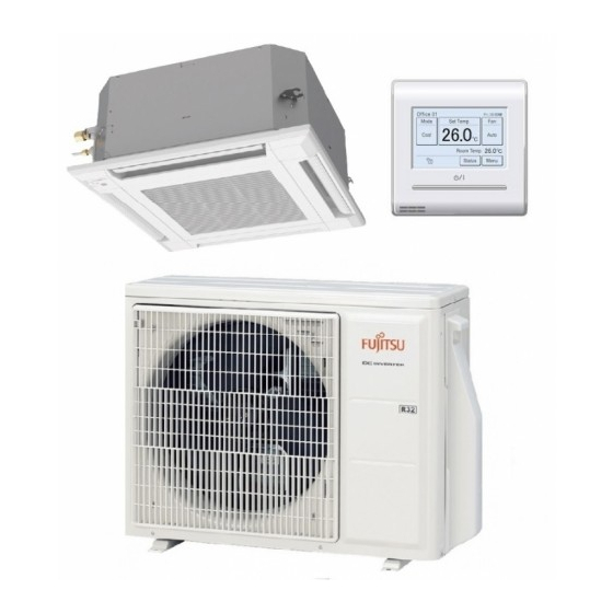
- Page 150 5. Accessories 5-1. Compact cassette type ¢ Models: AUXG07KVLA, AUXG09KVLA, AUXG12KVLA, AUXG14KVLA, AUXG18KVLA, and AUXG22KVLA Part name Exterior Q’ty Part name Exterior Q’ty Operating manual Drain hose insulation Operating manual Hose band (CD-ROM) Coupler heat insulation Installation manual (large) Coupler heat insulation...
- Page 151 5-2. Mini duct type ¢ Models: ARXG07KSLAP, ARXG09KSLAP, ARXG12KSLAP, and ARXG14KSLAP Part name Exterior Q’ty Part name Exterior Q’ty Operating manual Drain hose Operating manual Hose band (CD-ROM) Installation manual Drain hose insulation B Installation template Washer (Carton top) Coupler heat insulation Cable tie (large) (large) Coupler heat insulation...
- Page 152 ¢ Model: ARXG18KSLAP Part name Exterior Q’ty Part name Exterior Q’ty Operating manual Drain hose Operating manual Hose band (CD-ROM) Installation manual Drain hose insulation B Installation template Washer (Carton top) Coupler heat insulation Cable tie (large) (large) Coupler heat insulation Cable tie (medium) (small) Insulation...
- Page 153 5-3. Slim duct type ¢ Models: ARXG07KLLAP, ARXG09KLLAP, ARXG12KLLAP, ARXG14KLLAP, and ARXG18KLLAP Part name Exterior Q’ty Part name Exterior Q’ty Operating manual Cable tie (Large) Installation manual Cable tie (Small) Installation template Drain hose Washer Hose band Coupler heat insulation Drain hose insulation B (Large) Coupler heat insulation...
- Page 154 5-4. Medium static pressure duct type ¢ Model: ARXG22KMLB Part name Exterior Q’ty Part name Exterior Q’ty Operating manual Cable tie (medium) Operating manual Cable tie (small) (CD-ROM) Coupler heat insulation Installation manual (large) Coupler heat insulation Hanger (small) M10 nut A Drain hose insulation (with flange) M10 nut B...
- Page 155 5-5. Wall mounted type ¢ Models: ASHG07–14KGTB, ASHG07–14KMTB, and ASHG07– 14KMCC Part name Exterior Q’ty Part name Exterior Q’ty Operating manual Cloth tape Operating manual Tapping screw (large) (CD-ROM) Installation manual Tapping screw (small) Remote controller Wall hook bracket Battery Filter holder Remote controller Air cleaning filters...
- Page 156 ¢ Models: ASHG07KGTE, ASHG09KGTE, ASHG12KGTE, and ASHG14KGTE Part name Exterior Q’ty Part name Exterior Q’ty Operating manual Cloth tape Operating manual Tapping screw (large) (CD-ROM) Installation manual Tapping screw (small) Remote controller Wall hook bracket Battery Filter holder Remote controller Air cleaning filters holder - (02-94) -...
- Page 157 ¢ Models: ASHG18KMTB, ASHG22KMTB, and ASHG24KMTB Part name Exterior Q’ty Part name Exterior Q’ty Operating manual Tapping screw (large) Installation manual Tapping screw (small) Remote controller Battery Remote controller Filter holder holder Cloth tape Air cleaning filters Wall hook bracket - (02-95) - 5-5.
- Page 158 ¢ Models: ASHG18KMTE, ASHG22KMTE, and ASHG24KMTE Part name Exterior Q’ty Part name Exterior Q’ty Operating manual Cloth tape Operating manual Tapping screw (large) (CD-ROM) Installation manual Tapping screw (small) Remote controller Wall hook bracket Remote controller Filter holder holder Battery Air cleaning filters - (02-96) - 5-5.
- Page 159 ¢ Models: ASHG07KMCE, ASHG09KMCE, ASHG12KMCE, and ASHG14KMCE Part name Exterior Q’ty Part name Exterior Q’ty Operating manual Cloth tape Operating manual Tapping screw (large) (CD-ROM) Installation manual Tapping screw (small) Remote controller Wall hook bracket Battery Filter holder Remote controller Air cleaning filters holder - (02-97) -...
- Page 160 ¢ Models: ASHG07KETA, ASHG09KETA, ASHG12KETA, ASHG14KETA, ASHG07KETA-B, ASHG09KETA-B, ASHG12KETA-B, ASHG14KETA-B, ASHG07KETE, ASHG09KETE, ASHG12KETE, ASHG14KETE, ASHG07KETE-B, ASHG09KETE-B, ASHG12KETE-B, and ASHG14KETE-B Part name Exterior Q’ty Part name Exterior Q’ty Operating manual Cloth tape Operating manual Tapping screw (large) (CD-ROM) Installation manual Tapping screw (small) Remote controller Wall hook bracket Battery...
- Page 161 5-6. Ceiling type ¢ Models: ABHG18KRTA and ABHG22KRTA Part name Exterior Q’ty Part name Exterior Q’ty Operating manual Insulation Operating manual Drain hose (CD-ROM) Installation manual Hose band Template Cable tie (large) M10 nut A Cable tie (small) (with flange) M10 nut B Remote controller cable (with spring lock...
- Page 162 5-7. Floor type ¢ Models: AGHG09KVCA, AGHG12KVCA, and AGHG14KVCA Part name Exterior Q’ty Part name Exterior Q’ty Operating manual (CD- Operating manual ROM) Installation manual Cloth tape Wall hook bracket Tapping screws (large) Remote controller Tapping screws (small) Battery Air cleaning filters Remote controller holder - (02-100) -...
- Page 163 5-8. Outdoor unit ¢ Model: AOHG30KBTA4 Part name Exterior Q’ty Part name Exterior Q’ty Adapter K: mm (in) Installation manual 12.70 (1/2) to 9.52 (3/8) Drain pipe ¢ Model: AOHG36KBTA5 Part name Exterior Q’ty Part name Exterior Q’ty Adapter K: mm (in) Installation manual 12.70 (1/2) to 9.52 (3/8)
- Page 164 6. Optional parts 6-1. Indoor unit ¢ Controllers Lineup Type Indoor unit type Wireless remote controller AR-REM4E AR-REM7E AR-REB1E AR-REW2E Compact cassette — — — — Mini duct — — — — Slim duct — — — — Medium static pressure duct —...
- Page 165 Type Indoor unit type Wired remote controller UTY-RNNGM UTY-RVNGM UTY-RLRG UTY-RNRGZ* UTY-RCRGZ1 Compact cassette ◌ ◌ ◌ ◌ ◌ Mini duct ◌ ◌ ◌ ◌ ◌ Slim duct ◌ ◌ ◌ ◌ ◌ Medium static pressure duct ◌ ◌ ◌ ◌...
- Page 166 Controllers Exterior Part name Model name Summary Easy finger touch operation with LCD Wired remote panel. Backlit LCD enables easy UTY-RNRGZ* controller operation in a dark room. Wire type: Non-polar 2-wire High visibility and easy operation. Room temperature can be accurately Wired remote UTY-RLRG controlled using the thermo sensor.
- Page 167 Exterior Part name Model name Summary Compact remote controller concentrates on the basic functions such as Start/Stop, fan control, Simple remote temperature setting, and operation UTY-RSNGM controller mode. Wire type: Polar 3-wire IR Receiver Kit Unit control is performed by wireless with Wireless UTY-LBTGM remote controller.
- Page 168 ¢ Cassette grille Lineup Indoor unit type Model Compact cassette UTG-UFGF-W Part Exterior Part name Model name Summary This cassette grille can be installed Cassette Grille UTG-UFGF-W appropriately on the grid type ceiling common in the office. - (02-106) - 6-1.
- Page 169 ¢ Others Lineup Type Air outlet shutter Insulation kit for Fresh air intake Half concealed Indoor unit type plate high humidity UTR-YDZB UTZ-KXGC UTZ-VXAA UTR-STA Compact cassette ◌ ◌ ◌ — Mini duct — — — — Slim duct —...
- Page 170 Type External input and output Indoor unit type External connect kit UTY-XWZX UTY-XWZXZ5 UTY-XWZXZG UTY-XCSXZ2 UTY-XCSX Compact cassette — — ◌ — ◌ Mini duct — — ◌ — — Slim duct — — ◌ — — Medium static pressure duct —...
- Page 171 Type Indoor unit type Communication kit Air cleaning filter UTY-TWBXF2 UTY-TWRXZ2 UTY-TWRXZ3 UTR-FA16-5 Compact cassette — — — — Mini duct — — — — Slim duct — — — — Medium static pressure duct — — — — KGTB —...
- Page 172 Type Drain Pump Indoor unit type Square Flange Round Flange Long-life Filter Unit UTD-SF045T UTD-RF204 UTD-LF25NA UTZ-PX1NBA Compact cassette — — — — Mini duct — — — — Slim duct — — — — Medium static pressure duct ◌ ◌...
- Page 173 Parts Exterior Part name Model name Summary Thermo-sensor for sensing the Remote Sensor UTY-XSZX temperature of arbitrary place in the Unit room. Width: 683 mm Auto Louver For 07, 09, 12, and 14 models UTD-GXTA-W Grille Kit Width: 883 mm Auto Louver UTD-GXTB-W Grille Kit...
- Page 174 Exterior Part name Model name Summary Required when external device is connected. External UTY-XWZXZ5 Connect Kit Use to connect with various peripheral devices and air conditioner PCB. External UTY-XWZXZG Connect Kit For control output port. Air Outlet Installed at the air outlet when 3- UTR-YDZB Shutter Plate directions mode is performed.
- Page 175 Exterior Part name Model name Summary Remotely manage an air conditioning system using mobile devices such as smartphones and tablets. For connection indoor unit with UART Wireless LAN interface. UTY-TFSXZ1 adapter Appropriate application for each region is required to use this option. For details, contact FGL sales company.
- Page 176 6-2. Outdoor unit ¢ Model: AOHG36KBTA5 Exterior Part name Model name Summary Set temperatures on timers to best meet individuals’ needs. Includes a large backlit LCD and 4-way navigation pad. Remote controller cable: 0.33 mm² (22AWG) NOTES: • The remote controller cable supplied with this controller is for indoor use.
- Page 177 7. Refrigerant system diagrams 7-1. Model: AOHG30KBTA4 Pressure switch CONDENSER - (02-115) - 7-1. Model: AOHG30KBTA4 7. Refrigerant system diagrams...
- Page 178 7-2. Model: AOHG36KBTA5 Pressure switch CONDENSER - (02-116) - 7-2. Model: AOHG36KBTA5 7. Refrigerant system diagrams...
- Page 179 8. Wiring diagrams 8-1. Compact cassette type ¢ Models: AUXG07KVLA, AUXG09KVLA, AUXG12KVLA, AUXG14KVLA, AUXG18KVLA, and AUXG22KVLA - (02-117) - 8-1. Compact cassette type 8. Wiring diagrams...
- Page 180 8-2. Mini duct type and Slim duct type ¢ Models: ARXG07KSLAP, ARXG09KSLAP, ARXG12KSLAP, ARXG14KSLAP, ARXG18KSLAP, ARXG07KLLAP, ARXG09KLLAP, ARXG12KLLAP, ARXG14KLLAP, and ARXG18KLLAP WLAN adapter, Converter etc. (Option) - (02-118) - 8-2. Mini duct type and Slim duct type 8. Wiring diagrams...
- Page 181 8-3. Medium static pressure duct type ¢ Model: ARXG22KMLB - (02-119) - 8-3. Medium static pressure duct type 8. Wiring diagrams...
- Page 182 8-4. Wall mounted type ¢ Models: ASHG07KGTB, ASHG09KGTB, ASHG12KGTB, and ASHG14KGTB - (02-120) - 8-4. Wall mounted type 8. Wiring diagrams...
- Page 183 ¢ Models: ASHG07KGTE, ASHG09KGTE, ASHG12KGTE, and ASHG14KGTE - (02-121) - 8-4. Wall mounted type 8. Wiring diagrams...
- Page 184 ¢ Models: ASHG18KMTB, ASHG22KMTB, and ASHG24KMTB - (02-122) - 8-4. Wall mounted type 8. Wiring diagrams...
- Page 185 ¢ Models: ASHG18KMTE, ASHG22KMTE, and ASHG24KMTE - (02-123) - 8-4. Wall mounted type 8. Wiring diagrams...
- Page 186 ¢ Models: ASHG07KMTB, ASHG09KMTB, ASHG12KMTB, and ASHG14KMTB - (02-124) - 8-4. Wall mounted type 8. Wiring diagrams...
- Page 187 ¢ Models: ASHG07KMCC, ASHG09KMCC, ASHG12KMCC, and ASHG14KMCC - (02-125) - 8-4. Wall mounted type 8. Wiring diagrams...
- Page 188 ¢ Models: ASHG07KMCE, ASHG09KMCE, ASHG12KMCE, and ASHG14KMCE - (02-126) - 8-4. Wall mounted type 8. Wiring diagrams...
- Page 189 ¢ Models: ASHG07KETA, ASHG09KETA, ASHG12KETA, ASHG14KETA, ASHG07KETA-B, ASHG09KETA-B, ASHG12KETA-B, and ASHG14KETA-B - (02-127) - 8-4. Wall mounted type 8. Wiring diagrams...
- Page 190 ¢ Models: ASHG07KETE, ASHG09KETE, ASHG12KETE, ASHG14KETE, ASHG07KETE-B, ASHG09KETE-B, ASHG12KETE-B, and ASHG14KETE-B - (02-128) - 8-4. Wall mounted type 8. Wiring diagrams...
- Page 191 8-5. Ceiling type ¢ Models: ABHG18KRTA and ABHG22KRTA - (02-129) - 8-5. Ceiling type 8. Wiring diagrams...
- Page 192 8-6. Floor type ¢ Models: AGHG09KVCA, AGHG12KVCA, and AGHG14KVCA - (02-130) - 8-6. Floor type 8. Wiring diagrams...
- Page 193 8-7. Outdoor unit ¢ Model: AOHG30KBTA4 - (02-131) - 8-7. Outdoor unit 8. Wiring diagrams...
- Page 194 ¢ Model: AOHG36KBTA5 - (02-132) - 8-7. Outdoor unit 8. Wiring diagrams...
- Page 195 9. PC board diagrams 9-1. Models: AUXG07KVLA, AUXG09KVLA, AUXG12KVLA, AUXG14KVLA, AUXG18KVLA, and AUXG22KVLA CONTROL UNIT 07 model : EZ-01835HSE 09 model : EZ-0181RHSE 12 model : EZ-0181SHSE Thermistor Characteristics. 14 model : EZ-0181CHSE 18 model : EZ-0181THSE 22 model : EZ-01810HSE...
- Page 196 9-2. Models: ARXG07KSLAP, ARXG09KSLAP, ARXG12KSLAP, ARXG14KSLAP, and ARXG18KSLAP CONTROL UNIT 07 model : EZ-01830HSE 09 model : EZ-01831HSE 12 model : EZ-01832HSE 14 model : EZ-01833HSE 18 model : EZ-02003HSE Thermistor Characteristics. Temperature ( 20 ( 30 Thermistor BLACK F200 THERMISTOR ( ROOM TEMP.
- Page 197 9-3. Models: ARXG07KLLAP, ARXG09KLLAP, ARXG12KLLAP, ARXG14KLLAP, and ARXG18KLLAP CONTROL UNIT 07 model : EZ-01834HSE 09 model : EZ-0181YHSE 12 model : EZ-01820HSE 14 model : EZ-01814HSE 18 model : EZ-01813HSE Thermistor Characteristics. Temperature ( 20 ( 30 Thermistor 33.62 k 12.54 k 8.04 k Thermistor ( Room temp.
- Page 198 9-4. Model: ARXG22KMLB CONTROL UNIT Thermistor Characteristics. EZ-02004HSE Temperature ( 20 ( 30 Thermistor 33.62 k 12.54 k 8.04 k Thermistor ( Room temp. ) 1.15 V 2.22 V 2.77 V CN8-1 BLACK THERMISTOR ( ROOM TEMP. ) F200 B02B-XASK-1-A CN8-2 BLACK UL1430 AWG26...
- Page 199 9-5. Models: ASHG07KGTB, ASHG09KGTB, ASHG12KGTB, and ASHG14KGTB CONTROL UNIT 07 model : EZ-0183LHSE 09 model : EZ-0183MHSE 12 model : EZ-0183PHSE 14 model : EZ-0183RHSE OPTION UNIT ( 2-WIRE REMOTE CONTROL ) 3.15A UTY-TWRXZ2 AC250V UL1015 AWG22 BLACK OUTDOOR UNIT UL1015 AWG22 WHITE POWER SOURCE...
- Page 200 9-6. Models: ASHG07KGTE, ASHG09KGTE, ASHG12KGTE, and ASHG14KGTE CONTROL UNIT 07 model : EZ-0210LHSE 09 model : EZ-0210MHSE 12 model : EZ-0210PHSE 14 model : EZ-0210RHSE OPTION (2-WIRE REMOTE CONTROLLER UNIT) TERMINAL JXO-T3102-3P-B UTY-TWRXZ2 AWG22 AWG22 BLACK REMOTE CN14 CN301 OUTDOOR UNIT CN300 AWG22 WHITE...
- Page 201 9-7. Models: ASHG18KMTB, ASHG22KMTB, and ASHG24KMTB CONTROL UNIT 18 model : EZ-02006HSE 22 model : EZ-02007HSE 24 model : EZ-02008HSE 2-WIRE REMOTE CONTROLLER UNIT ( OPTION ) UTY-TWRXZ2 CN5 DC Fan motor Terminal Lead wire Pin No. Function of terminal CN301 UL1007 AWG22 CN300...
- Page 202 9-8. Models: ASHG18KMTE, ASHG22KMTE, and ASHG24KMTE CONTROL UNIT 18 model : EZ-02110HSE 22 model : EZ-02111HSE 24 model : EZ-02112HSE OPTION (2-WIRE REMOTE CONTROLLER UNIT) TERMINAL JXO-T3102-3P-B UTY-TWRXZ2 AWG22 AWG22 BLACK REMOTE CN14 CN301 OUTDOOR UNIT CN300 AWG22 WHITE CONTROLLER B3 ( 5.0 ) B-XASK-1-A AWG26 B07B-PASK-1...
- Page 203 9-9. Models: ASHG07KMTB, ASHG09KMTB, ASHG12KMTB, and ASHG14KMTB CONTROL UNIT 07 model : EZ-0183EHSE 09 model : EZ-0183FHSE 12 model : EZ-0183DHSE 14 model : EZ-0183HHSE COMMUNICATION KIT ( OPTION ) UTY-TWBXF2 OUTDOOR UNIT BLACK 3.15A 250V WHITE 2013485-1 CNC01 POWER SOURCE REMOTE WHITE WHITE...
- Page 204 9-10. Models: ASHG07KMCC, ASHG09KMCC, ASHG12KMCC, and ASHG14KMCC CONTROL UNIT 07 model : EZ-019CHSE 09 model : EZ-019DHSE 12 model : EZ-019EHSE 14 model : EZ-019FHSE COMMUNICATION KIT ( OPTION ) UTY-TWBXF2 OUTDOOR UNIT BLACK 3.15A 250V WHITE 2013485-1 CNC01 POWER SOURCE REMOTE WHITE WHITE...
- Page 205 9-11. Models: ASHG07KMCE, ASHG09KMCE, ASHG12KMCE, and ASHG14KMCE CONTROL UNIT 07 model : EZ-0210FHSE 09 model : EZ-0216HSE 12 model : EZ-0217HSE 14 model : EZ-0218HSE OPTION (2-WIRE REMOTE CONTROLLER UNIT) TERMINAL JXO-T3102-3P-B UTY-TWRXZ2 AWG22 AWG22 BLACK REMOTE CN14 CN301 OUTDOOR UNIT CN300 AWG22 WHITE...
- Page 206 9-12. Models: ASHG07KETA, ASHG09KETA, ASHG12KETA, ASHG14KETA, ASHG07KETA-B, ASHG09KETA-B, ASHG12KETA-B, and ASHG14KETA-B CONTROL UNIT 07 model : EZ-0198HSE 09 model : EZ-0199HSE 12 model : EZ-019AHSE 14 model : EZ-019BHSE 2-WIRE REMOTE CONTROLLER UNIT ( OPTION ) UTY-TWRXZ2 CN5 DC Fan motor Terminal Lead wire Pin No.
- Page 207 9-13. Models: ASHG07KETE, ASHG09KETE, ASHG12KETE, ASHG14KETE, ASHG07KETE-B, ASHG09KETE-B, ASHG12KETE-B, and ASHG14KETE-B CONTROL UNIT 07 model : EZ-0210SHSE 12 model : EZ-0210WHSE 09 model : EZ-0210THSE 14 model : EZ-0210YHSE OPTION (2-WIRE REMOTE CONTROLLER UNIT) TERMINAL JXO-T3102-3P-B UTY-TWRXZ2 AWG22 AWG22 BLACK CN14 REMOTE CN301...
- Page 208 9-14. Models: ABHG18KRTA and ABHG22KRTA CONTROL UNIT 18 model : EZ-019GHSE 22 model : EZ-019HHSE EMI FILTER ZCAT1518-0730 CN8 Thermistor Characteristics. TERMINAL 2 TURNS DC12V Temperature REMOTE CONTROLLER UL1007 AWG22 ( 20 ( 30 14-1 Thermistor UL1007 AWG22 WHITE 14-2 2-WIRE TYPE ( OPTION ) 33.62 k 12.54 k...
- Page 209 9-15. Models: AGHG09KVCA, AGHG12KVCA, and AGHG14KVCA CONTROL UNIT 09 model : EZ-01915HSE 12 model : EZ-01916HSE 14 model : EZ-01917HSE INDICATOR PCB K20AE-2000HSE-D0 EMI FILTER GRFC-8 2 TURNS P1002 JB20-09HG UL1430 AWG22 BLACK WHITE 3.15A POWER SOURCE WHITE AC250V UL1430 AWG22 AC230V WHITE WHITE...
- Page 210 9-16. Model: AOHG30KBTA4 INVERTER ASSEMBLY 30 model : EZ-020SHUE P650 DC Fan motor1 & 2 Terminal Lead wire Function of terminal Pin No. code color EMI FILTER EMI FILTER Motor power voltage input KRFC-13 KRFC-13 EMI FILTER KRFC-13 2 TURNS 1 TURN UL1015 2 TURNS...
- Page 211 9-17. Model: AOHG36KBTA5 INVERTER ASSEMBLY 36 model : EZ-020THUE P650 DC Fan motor1 & 2 Terminal Lead wire Function of terminal Pin No. code color EMI FILTER EMI FILTER Motor power voltage input KRFC-13 KRFC-13 EMI FILTER KRFC-13 2 TURNS 1 TURN UL1015 2 TURNS...
- Page 212 - (02-150) - 9-17. Model: AOHG36KBTA5 9. PC board diagrams...
- Page 213 3. TROUBLESHOOTING 2022.08.08 SR_CH03_MU004EG_07...
- Page 214 CONTENTS 3. TROUBLESHOOTING 1. Error code ....................03-1 1-1. How to check the error memory..................03-1 1-2. How to erase the error memory ..................03-1 1-3. Error code table (Indoor unit and wired remote controller)..........03-2 1-4. Error code table (Outdoor unit) ..................03-4 1-5. Error code table (Wireless LAN indicator)...............03-6 1-6.
-
Page 215: Table Of Contents
CONTENTS (continued) 2-34. E: 86. High pressure switch error (Outdoor unit) ............03-50 2-35. E: 94. Over current error (Outdoor unit)..............03-51 2-36. E: 95. Compressor motor control error (Outdoor unit) ..........03-53 2-37. E: 97. Outdoor unit fan motor error (Outdoor unit) ............03-54 2-38. - Page 217 1. Error code When a problem occurs in the system or the connected device, the error content is notified by dis- playing the code. NOTE: This function is only available in a system with indoor or IR receiver units equipped with in- dicator lamps to show the error content.
- Page 218 1-3. Error code table (Indoor unit and wired remote controller) The operation, timer, and economy indicators operate according to the error contents. For confirmation of the error contents, refer the flashing pattern as follows. Indoor unit display Wired remote Error contents Operation [ ] Timer [ ] Economy [ ]...
- Page 219 Indoor unit display Wired remote Error contents Operation [ ] Timer [ ] Economy [ ] controller (Green) (Orange) (Green) display E: 73. Outdoor unit heat exchanger 7 times 3 times Continuous thermistor error (Outdoor unit) E: 74. Outdoor temperature thermistor error 7 times 4 times Continuous...
- Page 220 1-4. Error code table (Outdoor unit) The operation status is determined by the lighting up and blinking of the LED lamp. After check that ERROR LED lamp blinks, press the ENTER button once. NOTE: For the positions of LED lamp and buttons, refer to "Function settings (for outdoor unit)"...
- Page 221 MONITOR POWER/ Error contents ERROR MODE E: 77. Heat sink thermistor error (Outdoor ● ■ ■ ■ ○ ○ ○ ● unit) E: 86. High pressure switch error ● ■ ■ ■ ○ ○ ○ ● (Outdoor unit) E: 86. High pressure switch error ●...
- Page 222 1-5. Error code table (Wireless LAN indicator) • Wireless LAN control system diagram example Indoor unit Internet Controller PCB Cloud Wireless Parts: Mobile app Outdoor unit WLAN adapter (Smart device) router • Name of parts WLAN adapter Wireless LAN label MAC: SSID: AP-WF PIN:...
- Page 223 1-6. Error code table (Mobile App) • Error display If there is an abnormality on the air conditioning, refer to as follows. When the (error button) on the home screen is tapped, error code and error name is displayed. – For Android Error button Error code Error Name...
- Page 224 • Error code Error message Error contents Error code 11.1 Serial communication error E: 11. Serial communication error (Serial (Serial Reverse Transfer Error) reverse transfer error) (Outdoor unit) 11.2 11.3 Serial communication error E: 11. Serial communication error (Serial (Serial Forward Transfer Error) forward transfer error) (Indoor unit) 11.4 E: 12.
- Page 225 Error message Error contents Error code E: 86. High pressure switch error (Outdoor High pressure switch error 86.1 unit) Trip detection E: 94. Over current error (Outdoor unit) 94.1 95.1 E: 95. Compressor motor control error Compressor rotor position detection error (Outdoor unit) 95.3 E: 97.
- Page 226 1-7. Error message for wireless LAN control (Mobile App) • Error display If there is an abnormality on the wireless control system, refer to error messages as follows. The error message disappears after 5 seconds and the normal screen is displayed. For Android For iOS Error message...
- Page 227 • Error message list – For Android Registration error Error message Cause Solution Wi-Fi must be enabled to set The user has disabled the Enable the wireless LAN connection on the up new device wireless LAN connection on smart device. the smart device.
- Page 228 General error Error message Cause Solution No connectivity to Wi-Fi or The smart device has no Connect the mobile device to the Internet. the cloud. Please check your Internet access. network connection. An error occurred while trying to update your profile. Please try again later.
- Page 229 Registration error Error message Cause Solution Could not register the device. The router the air conditioner Check if the router connected to the air Make sure the device is is connected to, has no conditioner has Internet access. (You can ready for registration.
- Page 230 2. Troubleshooting with error code 2-1. E: 11. Serial communication error (Serial reverse transfer error) (Outdoor unit) Operation indicator 1 time flash Timer indicator 1 time flash Indicator Indoor unit Economy indicator Continuous flash Error code E: 11 Main PCB When the indoor unit cannot receive the serial signal from outdoor unit more than 2 minutes after power on, Detective actuator...
- Page 231 Check point 4. Check serial signal (Reverse transfer signal) Check serial signal (Reverse transfer signal) WHITE BLACK • Check if indicated value swings between AC 90 V and AC 270 V at the outdoor unit terminal 1 —3. • If it is abnormal, check the parts below. –...
- Page 232 2-2. E: 11. Serial communication error (Serial forward transfer error) (Indoor unit) Operation indicator 1 time flash Timer indicator 1 time flash Indicator Indoor unit Economy indicator Continuous flash Error code E: 11 Main PCB Indoor unit When the outdoor unit cannot properly receive the serial Detective actuator Fan motor signal from indoor unit for 10 seconds or more.
- Page 233 Check point 4. Check serial signal (Forward transfer signal) Check serial signal (Forward transfer signal) WHITE BLACK • Check if indicated value swings between AC 30 V and AC 130 V at outdoor unit terminal 2—3. • If it is abnormal, replace main PCB. ↓...
- Page 234 2-3. E: 12. Wired remote controller communication error (Indoor unit) Operation indicator 1 time flash Timer indicator 2 time flash Indicator Indoor unit Economy indicator Continuous flash Error code E: 12 Indoor unit Main PCB When the indoor unit cannot receive the signal from Detective actuator wired remote controller more than 1 minute during Wired remote control...
- Page 235 ↓ Check Point 2. Wire installation wrong remote controller group setting • Wrong wire connection in remote controller group (Please refer to the installation manual) • The number of connecting indoor unit and remote controller in one remote controller group were less than 16 units.
- Page 236 2-4. E: 18. External communication error (Indoor unit) Operation indicator 1 time flash Timer indicator 8 time flash Indicator Indoor unit Economy indicator Continuous flash Error code E: 18 External After receiving a signal from the external input and Detective actuator Indoor unit communication output PCB, the same signal has not been received for...
- Page 237 2-5. E: 22. Indoor unit capacity error (Indoor unit) Operation indicator 2 time flash Timer indicator 2 time flash Indicator Indoor unit Economy indicator Continuous flash Error code E: 22 When the total capacity of the indoor units does not Detective actuator Indoor unit main PCB match outdoor unit capacity while 3 minutes after power...
- Page 238 2-6. E: 23. Combination error (Outdoor unit) Operation indicator 2 time flash Timer indicator 3 time flash Indicator Indoor unit Economy indicator Continuous flash Error code E: 23 The outdoor unit receives the serial signal of applied Detective actuator Indoor unit refrigerant information from indoor unit.
- Page 239 2-7. E: 26. Address setting error in wired remote controller (Indoor unit) Operation indicator 2 time flash Timer indicator 6 time flash Indicator Indoor unit Economy indicator Continuous flash Error code E: 26 Wired remote controller (2-wire) • When the address number set by auto setting and manual setting are mixed in one remote controller group Detective actuator...
- Page 240 2-8. E: 29. Connected unit number error (Indoor unit) Operation indicator 2 time flash Timer indicator 9 time flash Indicator Indoor unit Economy indicator Continuous flash Error code E: 29 Wired remote controller (2-wire) When the number of the connected indoor unit exceeds Detective actuator the limitation.
- Page 241 2-9. E: 32. Indoor unit main PCB error (Indoor unit) Operation indicator 3 time flash Timer indicator 2 time flash Indicator Indoor unit Economy indicator Continuous flash Error code E: 32 When power is on and there is some below case. Detective actuator Indoor unit main PCB...
- Page 242 2-10. E: 33. Indoor unit motor electricity consumption detection error (Indoor unit) Operation indicator 3 time flash Timer indicator 3 time flash Indicator Indoor unit Economy indicator Continuous flash Error code E: 33 Indoor unit motor electricity When the voltage value or the current value of the motor Detective actuator consumption detection go beyond the limits...
- Page 243 2-11. E: 35. MANUAL AUTO button error (Indoor unit) Operation indicator 3 time flash Timer indicator 5 time flash Indicator Indoor unit Economy indicator Continuous flash Error code E: 35 Indoor unit controller PCB When the MANUAL AUTO button becomes on for Detective actuator Indicator PCB consecutive 60 or more seconds.
- Page 244 2-12. E: 39. Indoor unit power supply error for fan motor (Indoor unit) Operation indicator 3 time flash Timer indicator 9 time flash Indicator Indoor unit Economy indicator Continuous flash Error code E: 39 • When a momentary power cut off Detective actuator Indoor unit main PCB •...
- Page 245 2-13. E: 3A. Indoor unit communication circuit (wired remote controller) error Operation indicator 3 time flash Timer indicator 10 time flash Indicator Indoor unit Economy indicator Continuous flash Error code E: 3A Wired remote controller (2-wire) Detect the communication error of microcomputer and Detective actuator communication PCB.
- Page 246 2-14. E: 41. Room temperature sensor error (Indoor unit) Operation indicator 4 time flash Timer indicator 1 time flash Indicator Indoor unit Economy indicator Continuous flash Error code E: 41 Indoor unit main PCB Room temperature thermistor is open or short is Detective actuator detected always.
- Page 247 2-15. E: 42. Indoor unit heat exchanger sensor error (Indoor unit) Operation indicator 4 time flash Timer indicator 2 time flash Indicator Indoor unit Economy indicator Continuous flash Error code E: 42 Indoor unit main PCB When heat exchanger temperature thermistor open or Detective actuator Heat exchanger temperature short circuit is detected.
- Page 248 2-16. E: 45. Refrigerant leakage sensor error (Indoor unit) Operation indicator 4 time flash Timer indicator 5 time flash Indicator Indoor unit Economy indicator Continuous flash Error code E: 45 When refrigerant leakage sensor open, short circuit, or Detective actuator Refrigerant leakage sensor abnormal voltage of drive circuits detected.
- Page 249 2-17. E: 45. Refrigerant leakage sensor deterioration (Indoor unit) Operation indicator 4 time flash Timer indicator 5 time flash Indicator Indoor unit Economy indicator Continuous flash Error code E: 45 When refrigerant leakage sensor open, short circuit, or Detective actuator Refrigerant leakage sensor abnormal voltage of drive circuits detected.
- Page 250 2-18. E: 51. Indoor unit fan motor error (Indoor unit) Operation indicator 5 time flash Timer indicator 1 time flash Indicator Indoor unit Economy indicator Continuous flash Error code E: 51 main PCB When the actual rotation number of the indoor unit fan Detective actuator Indoor unit motor is below 1/3 of the target rotation number...
- Page 251 2-19. E: 53. Drain pump error (Indoor unit) Operation indicator 5 time flash Timer indicator 3 time flash Indicator Indoor unit Economy indicator Continuous flash Error code E: 53 Indoor unit main PCB Detective actuator When Float switch is ON for more than 3 minutes. Float switch Float switch failure Shorted connector/wire failure...
- Page 252 2-20. E: 57. Damper (Open/Close) detection limit switch error Operation indicator 5 time flash Timer indicator 7 time flash Indicator Indoor unit Economy indicator Continuous flash Error code E: 57 Indoor unit main PCB • When limit switch were not able to detect the close though the damper close.(Upper air flow) Limit switch Detective actuator...
- Page 253 2-21. E: 57. Damper (Open/Close) simultaneous detection limit switch error (Indoor unit) Operation indicator 5 time flash Timer indicator 7 time flash Indicator Indoor unit Economy indicator Continuous flash Error code E: 57 Indoor unit main PCB When the limit switch detects open and close at the Detective actuator simultaneous.
- Page 254 2-22. E: 58. Intake grille error (Indoor unit) Operation indicator 5 time flash Timer indicator 8 time flash Indicator Indoor unit Economy indicator Continuous flash Error code E: 58 Indoor unit main PCB When the Micro switch is detected open while running Detective actuator the compressor.
- Page 255 2-23. E: 5U. Indoor unit error Operation indicator 5 time flash Timer indicator 15 time flash Indicator Indoor unit Economy indicator Continuous flash Error code E: 5U Check point. Check following error code. E: 11. Serial communication error (Serial reverse transfer error) (Outdoor unit) E: 11.
- Page 256 2-24. E: 62. Outdoor unit model information error (Outdoor unit) Operation indicator 6 time flash Timer indicator 2 time flash Indicator Indoor unit Economy indicator Continuous flash Error code E: 62 When power is on and there is some below case. Detective actuator Outdoor unit main PCB...
- Page 257 2-25. E: 64. Active filter voltage error (Outdoor unit) Operation indicator 6 time flash Timer indicator 4 time flash Indicator Indoor unit Economy indicator Continuous flash Error code E: 64 Main PCB • When inverter input DC voltage is higher than 425 V or lower than 80 V.
- Page 258 2-26. E: 65. IPM error (Outdoor unit) Operation indicator 6 time flash Timer indicator 5 time flash Indicator Indoor unit Economy indicator Continuous flash Error code E: 65 When the signal from FO terminal terminal of IPM is “L” Detective actuator Outdoor unit Main PCB (0 V) during the compressor stopping.
- Page 259 2-27. E: 71. Discharge thermistor error (Outdoor unit) Operation indicator 7 time flash Timer indicator 1 time flash Indicator Indoor unit Economy indicator Continuous flash Error code E: 71 Outdoor unit main PCB When discharge pipe temperature thermistor open or Detective actuator short circuit is detected at power on or while running the Discharge pipe temperature...
- Page 260 2-28. E: 72. Compressor thermistor error (Outdoor unit) Operation indicator 7 time flash Timer indicator 2 time flash Indicator Indoor unit Economy indicator Continuous flash Error code E: 72 Outdoor unit main PCB When compressor temperature thermistor open or short Detective actuator circuit is detected at power on or while running the Compressor temperature thermistor...
- Page 261 2-29. E: 73. Outdoor unit heat exchanger thermistor error (Outdoor unit) Operation indicator 7 time flash Timer indicator 3 time flash Indicator Indoor unit Economy indicator Continuous flash Error code E: 73 Outdoor unit main PCB When heat exchanger temperature thermistor open or Detective actuator short circuit is detected at power on or while running the Heat exchanger temperature...
- Page 262 2-30. E: 74. Outdoor temperature thermistor error (Outdoor unit) Operation indicator 7 time flash Timer indicator 4 time flash Indicator Indoor unit Economy indicator Continuous flash Error code E: 74 Outdoor unit main PCB When outdoor temperature thermistor open or short Detective actuator circuit is detected at power on or while running the Outdoor temperature thermistor...
- Page 263 2-31. E: 76. 2-way valve thermistor error (Outdoor unit) Operation indicator 7 time flash Timer indicator 6 time flash Indicator Indoor unit Economy indicator Continuous flash Error code E: 76 Outdoor unit main PCB When 2-way valve temperature thermistor open or short Detective actuator circuit is detected at power on or while running the 2-way valve temperature thermistor...
- Page 264 2-32. E: 76. 3-way valve thermistor error (Outdoor unit) Operation indicator 7 time flash Timer indicator 6 time flash Indicator Indoor unit Economy indicator Continuous flash Error code E: 76 Outdoor unit main PCB When 3-way valve temperature thermistor open or short Detective actuator circuit is detected at power on or while running the 3-way valve temperature thermistor...
- Page 265 2-33. E: 77. Heat sink thermistor error (Outdoor unit) Operation indicator 7 time flash Timer indicator 7 time flash Indicator Indoor unit Economy indicator Continuous flash Error code E: 77 Detective actuator Heat sink temperature thermistor Heat sink temperature thermistor short or open detected Connector failure Forecast of cause Thermistor failure...
-
Page 266: E: 86. High Pressure Switch Error (Outdoor Unit)
2-34. E: 86. High pressure switch error (Outdoor unit) Operation indicator 8 time flash Timer indicator 6 time flash Indicator Indoor unit Economy indicator Continuous flash Error code E: 86 Outdoor unit main PCB When pressure switch open is detected in 10 seconds Detective actuator after the power is turned on. -
Page 267: E: 94. Over Current Error (Outdoor Unit)
2-35. E: 94. Over current error (Outdoor unit) Operation indicator 9 time flash Timer indicator 4 time flash Indicator Indoor unit Economy indicator Continuous flash Error code E: 94 Main PCB 1. When more than normal operating current to IPM in main PCB flows, the compressor stops. - Page 268 Check point 4. Check compressor Check compressor. (Refer to inverter compressor in "Service parts information".) ↓ Check point 5. Replace the main PCB If Check point 1 to 4 do not improve the symptom, replace the main PCB. ↓ - (03-52) - 2-35.
-
Page 269: E: 95. Compressor Motor Control Error (Outdoor Unit)
2-36. E: 95. Compressor motor control error (Outdoor unit) Operation indicator 9 time flash Timer indicator 5 time flash Indicator Indoor unit Economy indicator Continuous flash Error code E: 95 Main PCB 1. When running the compressor, if the detected rotor location is out of phase with actual rotor location more than 90°, the compressor stops. -
Page 270: E: 97. Outdoor Unit Fan Motor Error (Outdoor Unit)
2-37. E: 97. Outdoor unit fan motor error (Outdoor unit) Operation indicator 9 time flash Timer indicator 7 time flash Indicator Indoor unit Economy indicator Continuous flash Error code E: 97 Main PCB 1. When outdoor fan rotation speed is less than 100 rpm in 20 seconds after fan motor starts, fan motor stops. -
Page 271: E: 99. 4-Way Valve Error (Outdoor Unit)
2-38. E: 99. 4-way valve error (Outdoor unit) Operation indicator 9 time flash Timer indicator 9 time flash Indicator Indoor unit Economy indicator Continuous flash Error code E: 99 Indoor unit main PCB When the indoor heat exchanger temperature is compared with the room temperature, and either Heat exchanger temperature following condition is detected continuously two times,... - Page 272 Check point 3. Check the solenoid coil and 4-way valve • Solenoid coil Remove CN30 from PCB and check the resistance value of coil. Resistance value is about1.4 kΩ. → If it is open or abnormal resistance value, replace solenoid coil. •...
-
Page 273: E: 9A. Coil 1 (Expansion Valve 1) Error
2-39. E: 9A. Coil 1 (expansion valve 1) error Operation indicator 9 time flash Timer indicator 10 time flash Indicator Indoor unit Economy indicator Continuous flash Error code E: 9A EEV coil Detective actuator Coil (Expansion valve) driver circuit open detected. Main PCB EEV coil loose connection EEV wires cut or pinched... -
Page 274: E: A1. Discharge Temperature Error (Outdoor Unit)
2-40. E: A1. Discharge temperature error (Outdoor unit) Operation indicator 10 time flash Timer indicator 1 time flash Indicator Indoor unit Economy indicator Continuous flash Error code E: A1 Outdoor unit main PCB Protection stop by discharge temperature ≥ 110°C Detective actuator during compressor operation generated 2 times within Discharge temperature thermistor... - Page 275 Check point 5. Check the refrigerant amount Check the refrigerant leakage. ↓ Check point 6. Replace the main PCB If check point 1 to 5 do not improve the symptom, replace the main PCB. ↓ - (03-59) - 2-40. E: A1. Discharge temperature error (Outdoor unit) 2.
-
Page 276: E: A3. Compressor Temperature Error (Outdoor Unit)
2-41. E: A3. Compressor temperature error (Outdoor unit) Operation indicator 10 time flash Timer indicator 3 time flash Indicator Indoor unit Economy indicator Continuous flash Error code E: A3 Outdoor unit main PCB Protection stop by compressor temperature ≥ 110°C Detective actuator during compressor operation generated 2 times within Compressor temperature thermistor... - Page 277 Check point 5. Check the refrigerant amount Check the refrigerant leakage. ↓ Check point 6. Replace the main PCB If check point 1 to 5 do not improve the symptom, replace the main PCB. ↓ - (03-61) - 2-41. E: A3. Compressor temperature error (Outdoor unit) 2.
-
Page 278: E: A8. Refrigerant Leakage Sensor Error (Indoor Unit)
2-42. E: A8. Refrigerant leakage sensor error (Indoor unit) Operation indicator 10 time flash Timer indicator 8 time flash Indicator Indoor unit Economy indicator Continuous flash Error code E: A8 Detective actuator Refrigerant leakage sensor Forecast of cause Refrigerant leakage Check point 1. -
Page 279: Troubleshooting Without Error Code
3. Troubleshooting without error code 3-1. Indoor unit—No power Power supply failure Forecast of cause External cause Electrical components defective Check point 1. Check installation condition • Isn’t the breaker down? • Check loose or removed connection cable. -> If abnormal condition is found, correct it by referring to the installation manual or the “DESIGN & TECHNICAL MANUAL”. -
Page 280: Outdoor Unit-No Power
3-2. Outdoor unit—No power Power supply failure Forecast of cause External cause Electrical components defective Check point 1. Check installation condition • Is the circuit breaker on or off? • Check loose or removed connection cable. → If abnormal condition is found, correct it by referring to the installation manual or the “DESIGN & TECHNICAL MANUAL”. -
Page 281: No Operation (Power Is On)
3-3. No operation (Power is on) Setting/Connection failure Forecast of cause External cause Electrical components defective Check point 1. Check the indoor and outdoor installation condition • Indoor unit: – Check incorrect wiring between the indoor unit and remote controller. –... - Page 282 Check point 3. Check the wired remote controller and controller PCB [Compact cassette, slim duct, floor, ceiling type] Check voltage at CN14 (terminal 1—3) of main PCB or communication PCB. (Power supply to remote controller) • If it is DC 12 V, the remote controller is failure. (The controller PCB is normal) ->...
-
Page 283: No Cooling/No Heating
3-4. No cooling/No heating Indoor unit error Outdoor unit error Forecast of cause Effect by surrounding environment Connection pipe/Connection wire failure Refrigeration cycle failure Check point 1. Check Indoor unit • Does Indoor unit fan run in the HIGH mode? •... - Page 284 NOTES: • Strainer normally does not have temperature difference between inlet and outlet as shown be- low. Pipe (In) Pipe (Out) • If there is a difference like shown below, there is a possibility of inside clogged. In this case, re- place the strainer.
-
Page 285: Abnormal Noise
3-5. Abnormal noise Abnormal installation (indoor unit/outdoor unit) Forecast of cause Fan failure (indoor unit/outdoor unit) Compressor failure (outdoor) Diagnosis method when abnormal noise is occurred Abnormal noise is coming from Outdoor Abnormal noise is coming from Indoor unit. unit. (Check and correct followings) (Check and correct followings) ↓... -
Page 286: Water Leaking
3-6. Water leaking Erroneous installation Forecast of cause Drain hose failure Diagnosis method when water is spitting Diagnosis method when water leak occurs • Is main unit installed in stable condi- tion? Is the filter clogged? • Is main unit broken or deformed at the time of transportation or maintenance? ↓... -
Page 287: Troubleshooting With Error Code (For Wireless Lan Adapter)
4. Troubleshooting with error code (For wireless LAN adapter) 4-1. E: 18. External communication error between indoor unit and WLAN adapter Operation indicator 1 time flash Timer indicator 8 time flash Indoor unit Economy indicator Continuous flash Indicator Error code E: 18 LED1 (green) Flashing fast... -
Page 288: Wireless Lan Adapter Error
4-2. Wireless LAN adapter error Operation indicator No indication Timer indicator No indication Indoor unit Economy indicator No indication Indicator Error code — LED1 (green) Flashing fast Wireless LAN adapter LED2 (orange) Flashing fast Wireless LAN adapter setting When the setting button becomes on for consecutive 60 button seconds or more. -
Page 289: Network Communication Error Between Wireless Lan Router And Wlan Adapter
4-3. Network communication error between wireless LAN router and WLAN adapter Operation indicator No indication Timer indicator No indication Indoor unit Economy indicator No indication Indicator Error code — LED1 (green) Wireless LAN adapter LED2 (orange) Flashing fast Wireless LAN router When the not connection between wireless LAN adapter and wireless LAN router. - Page 290 Check point 4. Replace wireless LAN adapter. If check point 3 do not improve the symptom, replace the wireless LAN adapter and cancel the reg- istration of air conditioner on the mobile app. After replacing the adapter, perform the pairing on the mobile app. For the method of the mobile app, refer to "Mobile app setting method"...
-
Page 291: E: 18. Communication Error
4-4. E: 18. Communication error Operation indicator 1 time flash Timer indicator 8 time flash Indoor unit Economy indicator Continuous flash Indicator Error code E: 18 LED1 (green) Flashing fast Wireless LAN adapter LED2 (orange) Flashing fast Wireless LAN router When the external communication error between indoor unit and WLAN adapter and network communication Wireless LAN adapter PCB... - Page 292 Check point 3-1. Turn on the power again of air conditioner. If check point 1 to 2 do not improve the symptom, turn on the power of the air conditioner again and wait for 60 seconds. -> When the flashing pattern of the LED 2 (orange) is on, go to "Check point 3-2".
-
Page 293: E: 18. Wireless Lan Adapter Non-Energized
4-5. E: 18. Wireless LAN adapter non-energized Operation indicator 1 time flash Timer indicator 8 time flash Indoor unit Economy indicator Continuous flash Indicator Error code E: 18 LED1 (green) Wireless LAN adapter LED2 (orange) Indoor unit controller PCB When the voltage (DC 12 V) does not output from the Detective actuator controller PCB. -
Page 294: Mobile App Setting Method
4-6. Mobile app setting method ¢ Air conditioner deregistration method When the wireless LAN adapter is replaced, deregistration of all air conditioner is necessary on the mobile app. Launch the mobile app. FGL air Press and hold the registered device name of the air conditioner. If the Unregister button is displayed, tap the button. - Page 295 ¢ Air conditioner registration pairing method Choose the following modes to connect the air conditioner to the wireless LAN router. NOTES: • Before starting this setting, wait for 60 seconds or more after the power supply is connected to the air conditioner (via breaker or plug). •...
- Page 296 Confirm that the LED 2 blinks (on/off at 2 seconds intervals). Then press and hold the setting button on the WLAN Adapter for 3 seconds. on/off: 2 sec/2 sec on/off: 2 sec/0.5 sec The light pattern of the LED 2 changes. (On/off: 2 sec./2 sec. → 2 sec./0.5 sec.) Confirm both of the LED 1 and 2 are on to proceed.
- Page 297 Manual mode (For Android) Launch the mobile app. FGL air Sign in with your e-mail address and password following the screen on the mobile app. [email protected] Sign in Press the + button to add a new air conditioner. Select manual mode. Button mode Manual mode If both of the LED 1 and 2 are off, push the setting button once.
- Page 298 Manual mode (For iOS) Launch the mobile app. FGL air Sign in with your e-mail address and password following the screen on the mobile app. [email protected] Sign in Press the + button to add a new air conditioner. Select manual mode. Button mode Manual mode If both of the LED 1 and 2 are off, push the setting button once.
-
Page 299: Service Parts Information
5. Service parts information 5-1. Compressor Diagnosis method of compressor (If outdoor unit LED displays error, refer to troubleshooting) Does not start up Stops soon after starting up Abnormal noise ↓ ↓ ↓ Check if vibration noise by Is there open or loose con- Is there open or loose con- loose bolt or contact noise of nection cable? -
Page 300: Inverter Compressor
5-2. Inverter compressor ¢ Models: AOHG30KBTA4 and AOHG36KBTA5 Check point 1. Check connection • Check terminal connection of compressor (loose or incorrect wiring) W(C) V(S) (BLACK) (WHITE) Main PCB U(R) (RED) • Check terminal connection of main PCB (loose or incorrect wiring) Main PCB W400(U) W401(V) W402(W) - Page 301 Check point 3. Replace inverter PCB If check point 1 to 2 do not improve the symptom, replace main PCB. - (03-85) - 5-2. Inverter compressor 5. Service parts information...
-
Page 302: Outdoor Unit Electronic Expansion Valve (Eev)
5-3. Outdoor unit Electronic Expansion Valve (EEV) ¢ Models: AOHG30KBTA4 and AOHG36KBTA5 Check point 1. Check connections Check connection of connector. (Loose connector or open cable) NOTE: For details of wiring diagram, refer to "Wiring diagrams" in Chapter 2. TECHNICAL DATA AND PARTS LIST on page 02-117. - Page 303 Check point 6. Check strainer • Strainer normally does not have temperature difference between inlet and outlet as shown be- low. Pipe (In) Pipe (Out) • If there is a difference like shown below, there is a possibility of inside clogged. In this case, replace the strainer.
-
Page 304: Indoor Unit Fan Motor
5-4. Indoor unit fan motor ¢ Models: AUXG07KVLA, AUXG09KVLA, AUXG12KVLA, AUXG14KVLA, AUXG18KVLA, and ARXG22KMLB Check point 1. Check rotation of fan Rotate the fan by hand when operation is off. (Check if fan is caught, dropped off or locked motor) →... - Page 305 ¢ Models: ARXG07KSLAP, ARXG09KSLAP, ARXG12KSLAP, ARXG14KSLAP, ARXG18KSLAP, ARXG07KLLAP, ARXG09KLLAP, ARXG12KLLAP, ARXG14KLLAP, ARXG18KLLAP, ASHG12KGTB, ASHG14KGTB, ASHG12KGTE, ASHG14KGTE, ASHG18KMTB, ASHG22KMTB, ASHG24KMTB, ASHG18KMTE, ASHG22KMTE, ASHG24KMTE, ASHG07KMCE, ASHG09KMCE, ASHG12KMCE, ASHG14KMCE, ASHG14KETA, ASHG14KETA-B, ASHG14KETE, ASHG14KETE-B, and ABHG18KRTA Check point 1. Check rotation of fan Rotate the fan by hand when operation is off. (Check if fan is caught, dropped off or locked motor) →...
- Page 306 ¢ Models: ASHG07KGTB, ASHG09KGTB, ASHG07KGTE, ASHG09KGTE, ASHG07KETA, ASHG09KETA, ASHG12KETA, ASHG07KETA-B, ASHG09KETA-B, ASHG12KETA-B, ASHG07KETE, ASHG09KETE, ASHG12KETE, ASHG07KETE-B, ASHG09KETE-B, and ASHG12KETE-B Check point 1. Check rotation of fan Rotate the fan by hand when operation is off. (Check if fan is caught, dropped off or locked motor) →...
- Page 307 ¢ Models: ASHG07KMTB, ASHG09KMTB, ASHG12KMTB, ASHG14KMTB, ASHG07KMCC, ASHG09KMCC, ASHG12KMCC, and ASHG14KMCC Check point 1. Check rotation of fan Rotate the fan by hand when operation is off. (Check if fan is caught, dropped off or locked motor) → If fan or bearing is abnormal, replace it. Check point 2.
- Page 308 ¢ Models: AGHG09KVCA, AGHG12KVCA, and AGHG14KVCA Check point 1. Check rotation of fan Rotate the fan by hand when operation is off. (Check if fan is caught, dropped off or locked motor) → If fan or bearing is abnormal, replace it. Check point 2.
-
Page 309: Outdoor Unit Fan Motor
5-5. Outdoor unit fan motor ¢ Models: AOHG30KBTA4 and AOHG36KBTA5 Check point 1. Check rotation of fan Rotate the fan by hand when operation is off. (Check if fan is caught, dropped off or locked motor) → If fan or bearing is abnormal, replace it. Check point 2. -
Page 310: Thermistor Resistance Values
6. Thermistor resistance values 6-1. Indoor unit ¢ Room temperature thermistor Temperature (°C) Resistance (kΩ) Voltage (V) -10.0 58.25 0.73 -5.0 44.03 0.93 33.62 1.15 25.93 1.39 10.0 20.18 1.66 15.0 15.84 1.94 20.0 12.54 2.22 25.0 10.00 2.50 30.0 8.04 2.77 35.0... -
Page 311: Outdoor Unit
6-2. Outdoor unit ¢ Discharge temperature thermistor Temperature (°C) Resistance (kΩ) Voltage (V) -30.0 1,013.11 0.06 -25.0 729.09 0.09 -20.0 531.56 0.12 -15.0 392.31 0.16 -10.0 292.91 0.21 -5.0 221.09 0.28 168.60 0.36 129.84 0.46 10.0 100.91 0.57 15.0 79.12 0.71 20.0 62.55... - Page 312 ¢ Compressor temperature thermistor Temperature (°C) Resistance (kΩ) Voltage (V) -30.0 1,013.11 0.06 -25.0 729.09 0.09 -20.0 531.56 0.12 -15.0 392.31 0.16 -10.0 292.91 0.21 -5.0 221.09 0.28 168.60 0.36 129.84 0.46 10.0 100.91 0.57 15.0 79.12 0.71 20.0 62.55 0.86 25.0 49.84...
- Page 313 ¢ Heat exchanger temperature thermistor Temperature (°C) Resistance (kΩ) Voltage (V) -30.0 95.57 0.24 -25.0 68.89 0.32 -20.0 50.31 0.43 -15.0 37.19 0.57 -10.0 27.81 0.73 -5.0 21.02 0.92 16.05 1.14 12.38 1.39 10.0 9.63 1.65 15.0 7.56 1.93 20.0 5.98 2.21 25.0...
- Page 314 ¢ Heat exchanger (Middle) temperature thermistor Temperature (°C) Resistance (kΩ) Voltage (V) -30.0 95.57 0.24 -25.0 68.89 0.32 -20.0 50.31 0.43 -15.0 37.19 0.57 -10.0 27.81 0.73 -5.0 21.02 0.92 16.05 1.14 12.38 1.39 10.0 9.63 1.65 15.0 7.56 1.93 20.0 5.98 2.21...
- Page 315 ¢ 2-way valve thermistor, 3-way valve thermistor Temperature (°C) Resistance (kΩ) Voltage (V) -30.0 1,013.11 0.18 -25.0 729.09 0.25 -20.0 531.56 0.34 -15.0 392.31 0.44 -10.0 292.91 0.58 -5.0 221.09 0.74 168.60 0.93 129.84 1.14 10.0 100.91 1.38 15.0 79.12 1.63 20.0 62.55...
- Page 316 - (03-100) - 6-2. Outdoor unit 6. Thermistor resistance values...
- Page 317 4. CONTROL AND FUNCTIONS 2022.04.13 SR_CH04_MU004EG_08...
- Page 318 CONTENTS 4. CONTROL AND FUNCTIONS 1. Rotation number control of compressor...........04-1 1-1. Cooling operation ......................04-1 1-2. Heating operation ......................04-9 1-3. Dry operation ........................04-10 1-4. Rotation number of compressor at normal start-up ............04-16 1-5. Rotation number of compressor limitation by outdoor temperature ......04-17 2.
- Page 319 CONTENTS (continued) 8. Various protections...................04-78 8-1. Discharge gas temperature over-rise prevention control ..........04-78 8-2. Anti-freezing control (cooling and dry mode) ..............04-78 8-3. Current release control ....................04-79 8-4. Indoor unit fan motor over temperature protection............04-80 8-5. Compressor temperature protection ................04-81 8-6. High pressure protection ....................04-81 8-7.
-
Page 321: Rotation Number Control Of Compressor
C zone 20°C D zone Unit: rps Outdoor Indoor unit fan mode Model name temperature HIGH QUIET zone A zone AUXG07KVLA B zone AUXG09KVLA C zone AUXG12KVLA D zone A zone AUXG14KVLA B zone AUXG18KVLA C zone AUXG22KVLA D zone - (04-1) - 1-1. - Page 322 ¢ Mini duct type • Rotation number range of compressor Unit: rps Connected model name Minimum rotation number Maximum rotation number AOHG30KBTA4 AOHG36KBTA5 • Limit of maximum speed based on outdoor temperature A zone 26°C B zone 23°C C zone 20°C D zone Unit: rps...
- Page 323 ¢ Slim duct type • Rotation number range of compressor Unit: rps Connected model name Minimum rotation number Maximum rotation number AOHG30KBTA4 AOHG36KBTA5 • Limit of maximum speed based on outdoor temperature A zone 26°C B zone 23°C C zone 20°C D zone Unit: rps...
- Page 324 ¢ Medium static pressure duct type • Rotation number range of compressor Unit: rps Connected model name Minimum rotation number Maximum rotation number AOHG30KBTA4 AOHG36KBTA5 • Limit of maximum speed based on outdoor temperature A zone 26°C B zone 23°C C zone 20°C D zone...
- Page 325 ¢ Wall mounted type (For KGTB and KGTE) • Rotation number range of compressor Unit: rps Connected model name Minimum rotation number Maximum rotation number AOHG30KBTA4 AOHG36KBTA5 • Limit of maximum speed based on outdoor temperature A zone 26°C B zone 23°C C zone 20°C...
- Page 326 ¢ Wall mounted type (For KMTB, KMTE, KMCC, and KMCE) • Rotation number range of compressor Unit: rps Connected model name Minimum rotation number Maximum rotation number AOHG30KBTA4 AOHG36KBTA5 • Limit of maximum speed based on outdoor temperature A zone 26°C B zone 23°C...
- Page 327 ¢ Wall mounted type (For KETA and KETE) • Rotation number range of compressor Unit: rps Connected model name Minimum rotation number Maximum rotation number AOHG30KBTA4 AOHG36KBTA5 • Limit of maximum speed based on outdoor temperature A zone 26°C B zone 23°C C zone 20°C...
- Page 328 ¢ Ceiling type • Rotation number range of compressor Unit: rps Connected model name Minimum rotation number Maximum rotation number AOHG30KBTA4 AOHG36KBTA5 • Limit of maximum speed based on outdoor temperature A zone 26°C B zone 23°C C zone 20°C D zone Unit: rps Outdoor...
-
Page 329: Heating Operation
1-2. Heating operation A sensor (room temperature thermistor) built in indoor unit body will usually perceive difference or variation between setting temperature and present room temperature, and controls operation rota- tion number of compressor. • If the room temperature is 6.0 °C lower than a set temperature, the operation rotation number of compressor will attain to maximum performance. -
Page 330: Dry Operation
Zone is defined by set temperature and room temperature. ¢ Compact cassette type • Rotation number range of compressor Unit: rps Model name Outdoor temperature zone Operating rotation number AUXG07KVLA X zone J zone AUXG09KVLA Y zone AUXG12KVLA AUXG14KVLA X zone... - Page 331 ¢ Mini duct type • Rotation number range of compressor Unit: rps Model name Outdoor temperature zone Operating rotation number ARXG07KSLAP X zone ARXG09KSLAP J zone ARXG12KSLAP ARXG14KSLAP Y zone ARXG18KSLAP • Compressor control based on room temperature Room temperature rises Room temperature drops X zone Ts+1.5°C...
- Page 332 ¢ Medium static pressure duct type • Rotation number range of compressor Unit: rps Model name Outdoor temperature zone Operating rotation number X zone ARXG22KMLB J zone Y zone • Compressor control based on room temperature Room temperature rises Room temperature drops X zone Ts+1.5°C Ts+0.5°C...
- Page 333 ¢ Wall mounted type (For KMTB, KMTE, KMCC, and KMCE) • Rotation number range of compressor Unit: rps Model name Outdoor temperature zone Operating rotation number ASHG07KMCC ASHG09KMCC ASHG12KMCC X zone ASHG14KMCC ASHG07KMCE ASHG09KMCE ASHG12KMCE ASHG14KMCE ASHG07KMTB J zone ASHG09KMTB ASHG12KMTB ASHG14KMTB ASHG18KMTB...
- Page 334 ¢ Wall mounted type (For KETA and KETE) • Rotation number range of compressor Unit: rps Model name Outdoor temperature zone Operating rotation number ASHG07KETA ASHG07KETA-B ASHG09KETA X zone ASHG09KETA-B ASHG12KETA ASHG12KETA-B ASHG14KETA ASHG14KETA-B ASHG07KETE J zone ASHG07KETE-B ASHG09KETE ASHG09KETE-B ASHG12KETE ASHG12KETE-B Y zone...
- Page 335 ¢ Ceiling type • Rotation number range of compressor Unit: rps Model name Outdoor temperature zone Operating rotation number X zone ABHG18KRTA J zone ABHG22KRTA Y zone • Compressor control based on room temperature Room temperature rises Room temperature drops X zone Ts+1.5°C Ts+0.5°C...
-
Page 336: Rotation Number Of Compressor At Normal Start-Up
1-4. Rotation number of compressor at normal start-up ¢ Models: AOHG30KBTA4 and AOHG36KBTA5 Rotation number of the compressor soon after starting is controlled as below. Rotation number VI Rotation number V Rotation number IV Rotation number III Rotation number II Rotation number I Time 1 Time 2... -
Page 337: Rotation Number Of Compressor Limitation By Outdoor Temperature
1-5. Rotation number of compressor limitation by outdoor temperature The minimum rotation number of compressor is limited by outdoor temperature as below. • Cooling/Dry mode E zone 38°C D zone °C C zone °C B zone 7°C A zone Unit: rps Limitation of compressor Model name Outdoor temperature zone... -
Page 338: Auto Changeover Operation
2. Auto changeover operation When the air conditioner is set to AUTO mode by remote controller, operation starts in the optimum mode from among heating, cooling, dry and monitoring modes. During operation, the optimum mode is automatically switched in accordance with temperature changes. The temperature can be set be- tween 18°C and 30°C in 1.0°C steps. - Page 339 Operation flow chart Start Ts: Setting temperarure Monitor mode Room temp. > Ts+2°C? Room temp. < Ts-2°C? Middle zone Auto change over is second or more? Operation mode before the monitor mode is cooling mode? Operation mode of Heating operation Cooling operation outdoor unit: Cooling? Thermostat remains...
-
Page 340: Fan Control
3. Fan control Tr: Room temperature Ts: Setting temperature 3-1. Indoor fan control ¢ Compact cassette type Fan speed Indoor fan speed is defined as below. Speed (rpm) Operation mode Fan mode HIGH MED+ Heating QUIET Cool air prevention S-LOW HIGH Cooling/Fan... - Page 341 Cooling operation Switch the airflow AUTO, and indoor fan motor will run according to room temperature, as below. On the other hand, if switched in HIGH—QUIET, indoor motor will run at a constant airflow of COOL operation modes QUIET, LOW, MED, HIGH as shown in “Fan speed” above. Airflow change over (Cooling: Auto) Tr - Ts ≥...
- Page 342 Cool air prevention control (heating mode) The maximum value of the indoor fan speed is set as shown below, based on the detected tempera- ture by the indoor heat exchanger sensor on heating mode. • Normal operation Indoor heat exchanger temperature rises Indoor heat exchanger temperature drops...
- Page 343 • Powerful operation Indoor heat exchanger temperature rises Indoor heat exchanger POWERFUL temperature drops 42°C 37°C HIGH 39°C 34°C or setting fan mode* 37°C 32°C Cool air prevention 30°C 24°C S-LOW 13 minutes later: Indoor heat exchanger temperature rises Indoor heat exchanger POWERFUL temperature drops 42°C...
- Page 344 ¢ Mini duct type Fan speed Indoor fan speed is defined as below. Speed (rpm) Operation mode Fan mode HIGH 1,100 1,170 1,240 1,500 1,290 1,220 1,060 Heating 1,030 QUIET S-LOW HIGH 1,100 1,170 1,240 1,500 1,290 1,220 1,060 1,030 Cooling/Fan QUIET...
- Page 345 Heating operation Switch the airflow AUTO, and the indoor fan motor will run according to a room temperature, as be- low. On the other hand, if switched in HIGH—QUIET, the indoor motor will run at a constant airflow of HEAT operation modes QUIET, LOW, MED, HIGH as shown in “Fan speed”...
- Page 346 Moisture return prevention control (cooling and dry mode) Switch the airflow AUTO at cooling mode, and the indoor fan motor will run as shown below. Compressor Indoor fan setting airflow Indoor fan speed S-LOW 30 (sec) - (04-26) - 3-1.
- Page 347 ¢ Slim duct type Fan speed Indoor fan speed is defined as below. Speed (rpm) Operation mode Fan mode HIGH 1,160 1,260 1,340 1,560 1,380 1,000 1,160 1,240 1,400 1,300 Heating 1,060 1,140 1,240 1,220 QUIET 1,030 1,030 1,140 S-LOW HIGH 1,160...
- Page 348 Heating operation Switch the airflow AUTO, and the indoor fan motor will run according to a room temperature, as be- low. On the other hand, if switched in HIGH—QUIET, the indoor motor will run at a constant airflow of HEAT operation modes QUIET, LOW, MED, HIGH as shown in “Fan speed”...
- Page 349 Moisture return prevention control (cooling and dry mode) Switch the airflow AUTO at cooling mode, and the indoor fan motor will run as shown below. Compressor Indoor fan setting airflow Indoor fan speed S-LOW 30 (sec) - (04-29) - 3-1.
- Page 350 ¢ Medium static pressure duct type Fan speed Indoor fan speed is defined as below. Speed (rpm) Operation Fan mode mode ARXG22KMLB HIGH Heating QUIET S-LOW HIGH Cooling/Fan QUIET Soft quiet 350* S-LOW 350* X zone: 550 J zone: 550 *1: Fan mode only *2: Cooling mode only ...
- Page 351 Heating operation Switch the airflow AUTO, and the indoor fan motor will run according to a room temperature, as be- low. On the other hand, if switched in HIGH—QUIET, the indoor motor will run at a constant airflow of HEAT operation modes QUIET, LOW, MED, HIGH as shown in “Fan speed”...
- Page 352 Moisture return prevention control (cooling and dry mode) Switch the airflow AUTO at cooling mode, and the indoor fan motor will run as shown below. Compressor Indoor fan setting airflow Indoor fan speed S-LOW 30 (sec) - (04-32) - 3-1.
- Page 353 ¢ Wall mounted type (For KGTB) Fan speed Indoor fan speed is defined as below. Speed (rpm) Operation mode Fan mode ASHG07KGTB ASHG09KGTB ASHG12KGTB ASHG14KGTB POWERFUL 1,200 1,230 1,290 1,330 HIGH 1,130 1,160 1,220 1,260 MED+ 1,040 1,070 1,140 1,160 1,060 1,080...
- Page 354 Dry operation During dry operation, fan speed setting can not be changed as shown in “Fan speed” above. Heating operation Switch the airflow AUTO, and the indoor fan motor will run according to a room temperature, as be- low.
- Page 355 • Powerful operation Indoor heat exchanger temperature rises Indoor heat exchanger POWERFUL temperature drops 42°C 37°C HIGH 39°C 34°C 37°C 32°C Cool air prevention 30°C 28°C S-LOW 13 minutes later: Indoor heat exchanger temperature rises Indoor heat exchanger POWERFUL temperature drops 42°C 37°C HIGH...
- Page 356 ¢ Wall mounted type (For KGTE) Fan speed Indoor fan speed is defined as below. Speed (rpm) Operation mode Fan mode ASHG07KGTE ASHG09KGTE ASHG12KGTE ASHG14KGTE POWERFUL 1,200 1,230 1,290 1,330 HIGH 1,130 1,160 1,220 1,260 MED+ 1,040 1,070 1,140 1,160 1,060 1,080...
- Page 357 Dry operation During dry operation, fan speed setting can not be changed as shown in “Fan speed” above. Heating operation Switch the airflow AUTO, and the indoor fan motor will run according to a room temperature, as be- low.
- Page 358 • Powerful operation Indoor heat exchanger temperature rises Indoor heat exchanger POWERFUL temperature drops 42°C 37°C HIGH 39°C 34°C 37°C 32°C Cool air prevention 30°C 28°C S-LOW 13 minutes later: Indoor heat exchanger temperature rises Indoor heat exchanger POWERFUL temperature drops 42°C 37°C HIGH...
- Page 359 ¢ Wall mounted type (For KMTB, KMTE, KMCC, and KMCE) Fan speed Indoor fan speed is defined as below. Speed (rpm) Operation mode Fan mode ASHG07KMCC ASHG09KMCC ASHG12KMCC ASHG14KMCC ASHG07KMCE ASHG09KMCE ASHG12KMCE ASHG14KMCE POWERFUL 1,230 1,270 1,310 1,400 HIGH 1,160 1,200 1,240...
- Page 360 Speed (rpm) Operation mode Fan mode ASHG18KMTB ASHG22KMTB ASHG24KMTB ASHG18KMTE ASHG22KMTE ASHG24KMTE POWERFUL 1,400 1,470 1,570 HIGH 1,300 1,370 1,470 MED+ 1,230 1,230 1,230 1,130 1,130 1,130 Heating QUIET Cool air prevention S-LOW POWERFUL 1,400 1,470 1,570 HIGH 1,260 1,370 1,470 1,080 1,080...
- Page 361 Heating operation Switch the airflow AUTO, and the indoor fan motor will run according to a room temperature, as be- low. On the other hand, if switched in HIGH—QUIET, the indoor motor will run at a constant airflow of HEAT operation modes QUIET, LOW, MED, HIGH as shown in “Fan speed”...
- Page 362 • Powerful operation Indoor heat exchanger temperature rises Indoor heat exchanger POWERFUL temperature drops 42°C 37°C HIGH 39°C 34°C 37°C 32°C Cool air prevention 30°C 28°C S-LOW 13 minutes later: Indoor heat exchanger temperature rises Indoor heat exchanger POWERFUL temperature drops 42°C 37°C HIGH...
- Page 363 ¢ Wall mounted type (For KETA and KETE) Fan speed Indoor fan speed is defined as below. Speed (rpm) ASHG07KETA ASHG09KETA ASHG12KETA ASHG14KETA Operation Fan mode ASHG07KETA-B ASHG09KETA-B ASHG12KETA-B ASHG14KETA-B mode ASHG07KETE ASHG09KETE ASHG12KETE ASHG14KETE ASHG07KETE-B ASHG09KETE-B ASHG12KETE-B ASHG14KETE-B POWERFUL 1,210 1,250...
- Page 364 Dry operation During dry operation, fan speed setting can not be changed as shown in “Fan speed” above. Heating operation Switch the airflow AUTO, and the indoor fan motor will run according to a room temperature, as be- low.
- Page 365 • Powerful operation Indoor heat exchanger temperature rises Indoor heat exchanger POWERFUL temperature drops 42°C 37°C HIGH 39°C 34°C 37°C 32°C Cool air prevention 30°C 28°C S-LOW 13 minutes later: Indoor heat exchanger temperature rises Indoor heat exchanger POWERFUL temperature drops 42°C 37°C HIGH...
- Page 366 ¢ Ceiling type Fan speed Indoor fan speed is defined as below. Speed (rpm) Operation mode Fan mode ABHG18KRTA ABHG22KRTA HIGH 1,020 MED+ Heating QUIET Cool air prevention S-LOW HIGH 1,020 Cooling/Fan QUIET Soft quiet 500* 500* S-LOW 300* 300* X zone: 750 X zone: 750...
- Page 367 Heating operation Switch the airflow AUTO, and the indoor fan motor will run according to a room temperature, as be- low. On the other hand, if switched in HIGH—QUIET, the indoor motor will run at a constant airflow of HEAT operation modes QUIET, LOW, MED, HIGH as shown in “Fan speed”...
- Page 368 • Powerful operation Indoor heat exchanger temperature rises Indoor heat exchanger POWERFUL temperature drops 42°C 37°C HIGH 39°C 34°C or setting fan mode* 37°C 32°C Cool air prevention 30°C 24°C S-LOW 13 minutes later: Indoor heat exchanger temperature rises Indoor heat exchanger POWERFUL temperature drops 42°C...
- Page 369 ¢ Floor type Fan speed Indoor fan speed is defined as below. • Model: AGHG09KVCA Speed (rpm) Fan mode Operation mode Upper & Lower air flow (Upper/Lower) Upper air flow mode mode POWERFUL 1,230/1,040 1,300/ — HIGH 1,120/950 1,230/ — MED+ 1,000/850 1,090/ —...
- Page 370 • Model: AGHG14KVCA Speed (rpm) Fan mode Operation mode Upper & Lower air flow (Upper/Lower) Upper air flow mode mode POWERFUL 1,440/1,230 1,440/ — HIGH 1,330/1,120 1,370/ — MED+ 1,140/970 1,180/ — 1,140/970 1,180/ — Heating LOW- 940/800 1,020/ — QUIET 660/560 790/ —...
- Page 371 Heating operation Switch the airflow AUTO, and the indoor fan motor will run according to a room temperature, as be- low. On the other hand, if switched in HIGH—QUIET, the indoor motor will run at a constant airflow of HEAT operation modes QUIET, LOW, MED, HIGH as shown in “Fan speed”...
- Page 372 • Powerful operation Indoor heat exchanger temperature rises Indoor heat exchanger POWERFUL temperature drops 42°C 34°C HIGH 39°C 31°C 37°C 29°C Cool air prevention 30°C 24°C S-LOW 13 minutes later: Indoor heat exchanger temperature rises Indoor heat exchanger POWERFUL temperature drops 42°C 34°C HIGH...
-
Page 373: Outdoor Fan Control
3-2. Outdoor fan control ¢ Outdoor fan motor This outdoor unit has a DC fan motor. (Control method is different between AC and DC motors.) ¢ Fan speed Model: AOHG30KBTA4 Fan speed is defined by outdoor temperature and compressor frequency. Unit: rpm Fan step Cooling or dry... - Page 374 Model: AOHG36KBTA5 Fan speed is defined by outdoor temperature and compressor frequency. Unit: rpm Fan step Cooling or dry Heating S-HIGH — 1,200 1,150 — 1,150 — 1,150 — 1,080 1,200 1,150 1,080 • When the compressor frequency increases, the outdoor fan speed also changes to the higher speed.
-
Page 375: Louver Control
4. Louver control 4-1. Horizontal louver control ¢ Wall mounted type Each time the button is pressed, the air direction range will change as below: Side view • Remote controller display is not changed. • Vertical airflow direction is set automatically as shown, in accordance with the type of operation selected. - Page 376 ¢ Ceiling type Each time the button is pressed, the air direction range will change as below: • Remote controller display is not changed. • Vertical airflow direction is set automatically as shown, in accordance with the type of operation selected.
-
Page 377: Vertical Louver Control
4-2. Vertical louver control ¢ Wall mounted type (For KGTE and 18–24KMTB) Each time the button is pressed, the air direction range will change as below: Front view Remote controller display is not changed. 4-3. Adjust the horizontal louver ¢ Wall mounted type (For KGTB, KMTE, 07–14KMTB, KMCC, KMCE, KETA, and KETE) Move the horizontal louvers to adjust airflow direction you prefer. -
Page 378: Individual Louver Control
4-4. Individual louver control ¢ Compact cassette type To independently can be set the airflow pattern of each louver as follows: This function is given priority to overall louver control. But this function is release during the following operation. • Cold air prevention control •... -
Page 379: Swing Operation
4-6. Swing operation ¢ Compact cassette type • To select up/down airflow swing operation When the swing signal is received, the horizontal louver starts to swing. – Swinging range • Cooling mode/dry mode/fan mode: 1 ↔ 4 • Heating mode: 1 ↔ 4 –... -
Page 380: Timer Operation Control
5. Timer operation control 5-1. Wireless remote control ¢ Compact cassette, Mini duct, Slim duct, Medium static pressure duct, Wall mounted (For KGTE, 07–14KMTB, KMCC, and KMCE), and Ceiling types On/Off timer Program timer Sleep timer Weekly timer ○ ○ ○... - Page 381 Sleep timer If the sleep timer is set, the room temperature is monitored and the operation is stopped auto- matically. If the operation mode or the set temperature is change after the sleep timer is set, the operation is continued according to the changed setting of the sleep timer from that time on. •...
- Page 382 ¢ Wall mounted (For KGTB, 18–24KMTB, KMTE, KETA, and KETE) and Floor types On/Off timer Program timer Sleep timer Weekly timer ○ ○ ○ ○ On/Off timer • Off timer: When the clock reaches the set timer, the air conditioner will be turned off. Operation mode Stop mode Set time of timer...
- Page 383 Sleep timer If the sleep timer is set, the room temperature is monitored and the operation is stopped auto- matically. If the operation mode or the set temperature is change after the sleep timer is set, the operation is continued according to the changed setting of the sleep timer from that time on. •...
-
Page 384: Wired Remote Control
5-2. Wired remote control Temperature On/Off timer Program timer Sleep timer Weekly timer Setback Timer ○ ○ ○ ○ ○ ¢ On/Off timer • Off timer: When the clock reaches the set timer, the air conditioner will be turned off. Operation mode Stop mode Set time of timer... - Page 385 ¢ Sleep timer If the sleep timer is set, the room temperature is monitored and the operation is stopped auto- matically. If the operation mode or the set temperature is change after the sleep timer is set, the operation is continued according to the changed setting of the sleep timer from that time on. •...
- Page 386 ¢ Temperature Setback Timer • The temperature setback timer only changes the set temperature for 7 days, it cannot be used to start or stop air conditioner operation. • The temperature setback timer can be set to operate up to two times per day but only one temperature setting can be used.
-
Page 387: Defrost Operation Control
6. Defrost operation control Tn: Outdoor unit heat exchanger temperature Ta: Outdoor temperature Tn10: Temperature at 10 minutes after compressor start Tnb: Temperature before 5 minutes Triggering condition • The defrost operation starts when outdoor unit heat exchanger temperature sensor detects the temperature lower than the values shown below. -
Page 388: Defrost Operation In Heating Operation Stopped
6-1. Defrost operation in heating operation stopped If the outdoor unit is frosted when stopping the heating operation, it stops after performing the auto- matic defrosting operation. In this time, if the indoor unit operation lamp flashes slowly (6 sec on/2 sec off), the outdoor unit al- low the heat exchanger to defrost, and then stop. -
Page 389: Various Control
7. Various control 7-1. Auto restart When the power was interrupted by a power failure etc. during operation, the operation contents at that time are memorized and when the power is recovered, operation is automatically started with the memorized operation contents. Compact cassette, Mini duct, Slim duct, Wall mounted (For KGTE, 18–... -
Page 390: Forced Cooling Operation
7-3. Forced cooling operation The outdoor unit may not operate depending on the room temperature. When FORCED COOLING OPERATION button is pressed more than 10 seconds, forced cooling operation starts as shown in the table below. Operation mode Cooling Fan mode HIGH Timer mode Continuous (no timer setting available) -
Page 391: Economy Operation
7-5. ECONOMY operation The ECONOMY operation starts by pressing ECONOMY button on the remote controller. The ECONOMY operation is almost the same operation as below settings. Mode Cooling/Dry Heating Target temperature Setting temperature +1°C Setting temperature -1°C 7-6. POWERFUL operation ¢... -
Page 392: Compressor Preheating
7-8. Compressor preheating By preheating the compressor, warm airflow is quickly discharged when the operation is started. • Triggering condition – 30 minutes after compressor stopped. – Outdoor unit heat exchanger temperature (Tn) -2°C -4°C 7-9. External electrical heater control (For Compact cassette, Mini duct, Slim duct, Medium static pressure duct, KGTE, KMTE, KMCE, and KETE series wall mounted and Ceiling types) -
Page 393: Drain Pump Control
7-11. Drain pump control ¢ Drain control for cooling operation (For Mini duct and Ceiling types) During the compressor in operation • Triggering condition The thermostat is turned on during cooling or dry mode. • Operation details The drain pump is turned on. •... - Page 394 Overflow control • Triggering condition The float switch is turned on. • Operation details – The drain pump is turned on. – When the operation mode is cooling or dry, operate the followings. • The compressor is stopped. • Then indoor fan control is turned off. •...
- Page 395 ¢ Drain control for defrosting operation (For Compact cassette, Slim duct, and Medium static pressure duct types) During cooling or dry mode • When the compressor starts, the drain pump starts simultaneously. • The drain pump operates continuously for 3 minutes after the compressor is turned off. Compressor Drain pump 3 minutes...
-
Page 396: Prevention To Restart For 3 Minutes (3 Minutes St)
During heating mode or fan mode and when operation is stopped • Triggering condition Drain pump is turned on at the same time that the float switch is turned on. • Operation details When the float switch turns on continuously for 3 minutes, "failure indication" operates. There- after, even if the float switch turns off, the "failure indication"... -
Page 397: Human Sensor For Energy Saving (For Kgtb Series And Kgte Series Wall Mounted And Ceiling Types)
7-14. Human sensor for energy saving (For KGTB series and KGTE series wall mounted and Ceiling types) If no one enters the room for approximately 20 minutes, the set temperature is automatically con- trolled. (When someone comes back into the room, the human sensor detect this, and automatically revert to the original settings.) Operation details (If there is no one in the room for a while) -
Page 398: Various Protections
8. Various protections 8-1. Discharge gas temperature over-rise prevention control The discharge gas temperature sensor (discharge thermistor: outdoor unit side) detects the dis- charge gas temperature. • When the discharge temperature becomes higher than the trigger condition, the compressor fre- quency is decreased as the table below, and it continues to decrease until the discharge tempera- ture becomes lower than the trigger condition. -
Page 399: Current Release Control
8-3. Current release control The rotation number of compressor is controlled so that the outdoor unit input current does not ex- ceeds current limit value set according to the outdoor temperature. The rotation number of compressor returns according to the operation mode, when the current be- comes lower than the release value. -
Page 400: Indoor Unit Fan Motor Over Temperature Protection
8-4. Indoor unit fan motor over temperature protection ¢ Compact cassette and Ceiling types When satisfy the following conditions, the protection works. • After the 90 seconds from the fan operation, detect less than 300 rpm for 10 seconds. • IPM trip protection works. •... -
Page 401: Compressor Temperature Protection
8-5. Compressor temperature protection When the compressor temperature sensor detects higher than the trigger condition below, the com- pressor is stopped. When the compressor temperature sensor detects the release condition, the pro- tection is released. Trigger condition 108°C 80°C Release condition (3 minutes after compressor stop) 8-6. -
Page 402: High Temperature And High Pressure Release Control
8-8. High temperature and high pressure release control The compressor is controlled as follows. ¢ Models: AOHG30KBTA4 and AOHG36KBTA5 • Cooling mode Indoor unit heat exchanger Indoor unit heat exchanger temperature rises temperature drops 61°C Zone A 60°C 59°C Zone B 54°C Zone C Zone D... - Page 403 5. FILED WORKING 2022.08.08 SR_CH05_MU004EG_08...
- Page 404 CONTENTS 5. FILED WORKING 1. Function settings (for indoor unit).............05-1 1-1. Compact cassette, Mini duct, Slim duct types indoor unit (setting by DIP switch) ..05-1 1-2. Indoor unit (setting by wireless remote controller) ............05-3 1-3. Indoor unit (setting by wired remote controller).............05-20 1-4.
-
Page 405: Function Settings (For Indoor Unit)
1. Function settings (for indoor unit) To adjust the functions of this product according to the installation environment, various types of function settings are available. NOTE: Incorrect settings can cause a product malfunction. 1-1. Compact cassette, Mini duct, Slim duct types indoor unit (setting by DIP switch) By using some components on the PCB, you can change the function settings. - Page 406 ¢ DIP switch setting • SW100: Remote controller address setting When operating a number of indoor units by using a wired remote controller, DIP switch set- ting for assigning unit number to each indoor unit is required. The slide switches are normally set to make the unit number 00. Remote Switch number controller...
-
Page 407: Indoor Unit (Setting By Wireless Remote Controller)
1-2. Indoor unit (setting by wireless remote controller) CAUTION This setting changes the function settings used to control the indoor unit according to the installa- tion conditions. Incorrect settings can cause a product malfunction. • After the power is turned on, perform the “Function setting” according to the installation conditions using the remote controller. - Page 408 ¢ AR-REM4E (for Wall mounted type KGTB), AR-REW3E (for Wall mounted type KGTE), AR-REW4E (for Wall mounted type KETA and KETE), AR-REW2E (for Wall mounted type KMTB and KMTE), and AR-REM7E (for Floor type) Button name and function During address setting mode, indoor unit reject the any operation command from remote con- troller.
- Page 409 Function setting procedure Connect the power supply of the outdoor unit. To enter the function setting mode, while holding down the POWERFUL and TEMP. button, press the RESET button. POWERFUL TEMP. ( RESET Function setting mode display Select the function number by pressing the or the buttons.
- Page 410 Press the MODE button once to transmit the function mode information. Press the button once to transmit the function setting information. 2 short beeps will be emitted from the indoor unit when the signal is received correctly. If wrong code is set, no beep sound will be emitted.
- Page 411 Resetting the power after setting up all indoor units Important: • If the reset is not performed, function cannot be read correctly. • After all the functions have been set, the circuit breaker needs to be switched off for at least 2 minutes.
- Page 412 Remote controller custom code setting Custom code setting of wireless remote controller needs to be same as the setting of the indoor unit. When you change the custom code setting of the wireless remote controller, do as follows: Press the START/STOP button until only the clock is displayed on the display. Press the MODE button for at least 5 seconds to display the current custom code (initially set to Press the TEMP.
- Page 413 ¢ AR-REB1E (for Wall mounted type KMCC) and AR-RMB1E (for Wall mounted type KMCE) Button name and function During address setting mode, indoor unit reject the any operation command from remote con- troller. Function number Refer to Function details. Setting number Refer to Function details.
- Page 414 Function setting procedure Connect the power supply of the outdoor unit. To enter the function setting mode, while holding down the POWERFUL and SET TEMP. buttons, press the RESET button. POWERFUL SET TEMP. ( RESET Function setting mode display Select the function number by pressing the or the buttons.
- Page 415 Press the MODE button once to transmit the function mode information. 2 short beeps Press the button once to transmit the function setting information. 2 short beeps will be emitted from the indoor unit when the signal is received correctly. If wrong code is set, no beep sound will be emitted.
- Page 416 Resetting the power after setting up all indoor units Important: • If the reset is not performed, function cannot be read correctly. • After all the functions have been set, the circuit breaker needs to be switched off for at least 2 minutes.
- Page 417 Remote controller custom code setting Custom code setting of wireless remote controller needs to be same as the setting of the indoor unit. When you change the custom code setting of the wireless remote controller, do as follows: Press the START/STOP button until only the clock is displayed on the display. Press the MODE button for at least 5 seconds to display the current custom code (initially set to Press the SET TEMP.
- Page 418 ¢ UTY-LNTG (for Compact cassette type) or AR-REJ1E (included in UTY-LBTGM for Duct type) Button name and function During address setting mode, indoor unit reject the any operation command from remote con- troller. Function number Refer to Function details. Setting number Refer to Function details.
- Page 419 Function setting procedure Connect the power supply of the outdoor unit. To enter the function setting mode, while holding down the ECONOMY and SET TEMP. buttons, press the RESET button. ECONOMY SET TEMP. ( RESET Function setting mode display - (05-15) - 1-2.
- Page 420 Select the function number by pressing the or the buttons. Each time the 10°C HEAT button is pressed, it switches between the right digit and the left digit. Change digit Change digit Proceed to the setting number by pressing the ECONOMY button. (To return to the function number selection, press the ECONOMY button again.) Select the function number by pressing the or the...
- Page 421 Press the button once to transmit the function setting information. 1 short beep will be emit- ted from the indoor unit or the IR receiver when the signal is received correctly. If wrong code is set, no beep sound will be emitted. 1 short beep NOTE: Press button within 30 seconds after pressing MODE button.
- Page 422 Setting up each indoor unit Repeat step from 1. to 8. to set up each indoor unit. If the custom code is other than " ", steps from 1. to 2. and 8. need to be performed. Resetting the power after setting up all indoor units Important: •...
- Page 423 Remote controller custom code setting Custom code setting of wireless remote controller needs to be same as the setting of the indoor unit. When you change the custom code setting of the wireless remote controller, do as follows: Press the START/STOP button until only the clock is displayed on the display. Press the MODE button for at least 5 seconds to display the current custom code (initially set to Press the SET TEMP.
-
Page 424: Indoor Unit (Setting By Wired Remote Controller)
1-3. Indoor unit (setting by wired remote controller) • The function settings of the control of the indoor unit can be changed by this procedure according to the installation conditions. Incorrect settings can cause the indoor unit malfunction. • After the power is turned on, perform the “Function setting” according to the installation conditions using the remote controller. - Page 425 ¢ UTY-RNNGM Button name and function During address setting mode, indoor unit reject the any operation command from remote controller. Function number Refer to Function details Remote controller address Setting number Refer to Function details Λ SET TEMP. “V” and “ ”...
- Page 426 Confirm the setting by pressing the TIMER SET button. The data will be transferred to the indoor unit. Not good Good ● Data is not set up on the indoor unit Data is correctly set up on the indoor unit correctly (-- is displayed.) (Flashing display changes to illuminated display.) ●...
- Page 427 ¢ UTY-RLRG Setting procedure by using wired remote controller The function number and the associated setting value are displayed on the LCD of the remote con- troller. Follow the instructions written in the local setup procedure supplied with the remote controller, and select appropriate setting according to the installation environment.
- Page 428 Pressing the "+" or "-" button, to select the function number. Then press the "ENTER" button. Function number Pressing the "+" or "-" button, to select the setting number. Then press the "ENTER" button. Setting number Example: Function number 30 Setting number 01 Error Good...
- Page 429 ¢ UTY-RVNGM Function setting procedure Connect the power supply of the outdoor unit. Switch to the function setting mode. When [Menu button] is pressed twice while “Monitor” screen is displayed, it switches to the “Submenu” screen. If [Menu button] is pressed while the “Submenu” screen is displayed, the display returns to the “Monitor”...
- Page 430 Select the [Function No.] with pressing the [Cursor button (Left/Right)], and select the Function No. to be set with pressing the [Cursor button (Up/Down)]. Function setting Mo 10:00AM R.C. Function Setting address Cancel: Version Error history Select the [Setting No.] with pressing the [Cursor button (Left/Right)], and select the Setting No. to be set with pressing the [Cursor button (Up/Down)].
- Page 431 When [Cancel button] is pressed twice while “Function setting” screen is displayed, it switches to the “Submenu” screen. Function setting Mo 10:00AM R.C. Function Setting Submenu Mo 10:00AM address Date and time Screen Cancel: Filter sign Version Error history R.C. sensor control Room temp.
- Page 432 ¢ UTY-RNRGZ* Setting procedure by using wired remote controller The function number and the associated setting value are displayed on the LCD of the remote con- troller. Follow the instructions written in the local setup procedure supplied with the remote controller, and select appropriate setting according to the installation environment.
- Page 433 “Function No.” screen is displayed. Set the “Function No.” with Function No. Cancel When the “OK” is touched, the display returns to the “Function Setting” screen. Touch the “Function No.” on the “Function Setting” screen. Function Setting Address [002–01] Function No. [30] Setting No.
- Page 434 Touch the “Yes” of the verification screen. Function Setting Function setting will be performed. OK? In case of “ERROR” In case of “OK” Function Setting Function Setting Address [002–01] Address [002–01] Function No. [30] Function No. [30] Setting No. [01] Setting No.
-
Page 435: Indoor Unit (Setting By Simple Remote Controller)
1-4. Indoor unit (setting by simple remote controller) • The function settings of the control of the indoor unit can be changed by this procedure according to the installation conditions. Incorrect settings can cause the indoor unit malfunction. • After the power is turned on, perform the “Function setting” according to the installation conditions using the remote controller. - Page 436 ¢ UTY-RSNGM Button name and function During address setting mode, indoor unit reject the any operation command from remote controller. Function number Setting number Refer to Function details Refer to Function details Remote controller address START/STOP button Transmits function setting FAN button SET TEMP.
- Page 437 Select the setting number by pressing the SET TEMP. or SET TEMP. button. The setting number indicator flashes during setting number selection. Setting number Example) Function number : 30, Setting number : 01 Confirm the setting by pressing the TIMER SET button. The data will be transferred to the indoor unit.
- Page 438 Resetting the power after setting up function of all indoor units NOTES: • If the reset is not performed, function cannot be read correctly. • After all the functions have been set, the circuit breaker needs to be switched off for at least 2 minutes.
- Page 439 ¢ UTY-RSRG/UTY-RHRG Setting procedure by using wired remote controller The function number and the associated setting value are displayed on the LCD of the remote con- troller. Follow the instructions written in the local setup procedure supplied with the remote controller, and select appropriate setting according to the installation environment.
- Page 440 Select the item number to be set with the SET TEMP. or SET TEMP. button, and press button to switch to the setting screen. Select the “13” in Menu 2-F1 settings. Then, press the button. Select the 2-wire remote controller address with the SET TEMP. or SET TEMP.
- Page 441 Setting results are displayed after data transmission. Press the button to return to the 2-wire remote controller address selection screen of step 9. If setting has been completed, press the FAN button to return to the Menu 2-F1 item se- lection screen.
-
Page 442: Function Details
1-5. Function details ¢ Contents of function setting Each function setting listed in this section is adjustable in accordance with the installation environ- ment. NOTE: Setting will not be changed if invalid numbers or setting values are selected. Function setting list Medium Functio Compact... - Page 443 Wall mounted Functio Functions n no. KGTB KGTE KMTB KMTE KMCC KMCE KETA KETE Remote controller ● — ● — ● — ● — address setting Filter sign ● ● ● ● ● ● ● ● Ceiling height — — —...
- Page 444 1) Remote controller address setting (for Wall-mounted type only) NOTES: • Because this setting is normally done automatically when 2-wire-type wired remote controller is installed, setting is unnecessary. • This setting is configurable only by wireless remote controller, but not configurable by Polar 3- wired remote controller.
- Page 445 3) Ceiling height (for Compact cassette type and Ceiling type only) Select the appropriate ceiling height according to the place of installation. Function number Setting value Setting description Factory setting Standard ♦ High ceiling For the specific height for each setting value, refer to “Installation space” in Chapter 2. "Dimensions"...
- Page 446 6) Static pressure (for Mini duct type and Slim duct type) Select the appropriate static pressure according to the installation conditions. For mini duct type: Function number Setting value Setting description Factory setting 0 Pa 10 Pa 20 Pa 30 Pa 40 Pa 50 Pa Standard...
- Page 447 8) Room temperature control for indoor unit sensor NOTE: If the remote sensor unit option is selected, perform this setting. Depending on the installed environment, correction of the room temperature sensor may be re- quired. Select the appropriate control setting according to the installed environment. The temperature of the room temperature sensor is corrected as follows: Corrected temp.
- Page 448 9) Room temperature control for wired remote controller sensor (for other than Floor type) Depending on the installed environment, correction of the wire remote temperature sensor may be required. Select the appropriate control setting according to the installed environment. To change this setting, set Function 42 to Both “01”. Ensure that the Thermo Sensor icon is displayed on the remote controller screen.
- Page 449 12) Remote controller custom code (Only for wireless remote controller) The indoor unit custom code can be changed. Select the appropriate custom code. Function number Setting value Setting description Factory setting ♦ 13) External input control "Operation/Stop" mode or "Forced stop" mode can be selected. Function number Setting value Setting description...
- Page 450 16) Switching functions for external output terminal (For other than 18-24KMTB and KETA mod- els in Wall-mounted type) Functions of the external output terminal can be switched. For details, refer to “External input and output”. Function number Setting value Setting description Factory setting Operation status ♦...
-
Page 451: Wired Remote Controller (Uty-Rnngm)
1-6. Wired remote controller (UTY-RNNGM) Prohibited Dual remote controller setting Prohibited DIP switch 1 °F/°C switch Prohibited Memory backup setting * Do not use DIP switch 2. ¢ Switch location Front case (back side) DIP switch 2 DIP switch 1 ¢... - Page 452 SW6: Memory backup setting Set to “ON” to use batteries for the memory backup. When batteries are not used, all of settings stored in memory will be deleted if there is a power failure. Memory backup Factory setting Disable ♦...
-
Page 453: Wired Remote Controller (Uty-Rvngm)
1-7. Wired remote controller (UTY-RVNGM) Memory backup setting DIP switch 1 Dual remote controller setting ¢ Switch location ¢ DIP switch setting SW1: Memory backup setting Set to “ON” to use batteries for the memory backup. When batteries are not used, all of settings stored in memory will be deleted if there is a power failure. -
Page 454: Wired Remote Controller (Uty-Rlrg)
1-8. Wired remote controller (UTY-RLRG) DIP switch Memory backup setting ¢ Switch location Front case (back side) Set the DIP switch to ON ¢ Dip switch setting SW1: Memory backup setting Set to “ON” to use batteries for the memory backup. When batteries are not used, all of settings stored in memory will be deleted if there is a power failure. -
Page 455: Simple Remote Controller (Uty-Rsngm)
1-10. Simple remote controller (UTY-RSNGM) Prohibited Dual remote controller setting °F/°C switch DIP switch Prohibited Prohibited Prohibited ¢ Switch location DIP Switch ¢ DIP switch setting SW2: Dual remote controller setting Set the remote controller SW2 according to the following table. Primary unit Secondary unit Number of remote controller... -
Page 456: Function Settings (For Outdoor Unit)
2. Function settings (for outdoor unit) Perform appropriate function setting locally according to the installation environment. NOTE: Incorrect settings can cause a product malfunction. CAUTION • Before setting up the switch buttons, discharge the static electricity from your body. • Never touch the terminals or the patterns on the parts that are mounted on the PCB. 2-1. - Page 457 ¢ Setting method Various settings can be adjusted by changing DIP switches and push switches on the PCB of the outdoor unit. LED display part POWER MONITOR ERROR /MODE ( GRN ) ( RED ) TEST RUN / SET 1 SET 2 CHECK PUMP DOWN...
- Page 458 ¢ Description of display LED lamp Function or operation method • Turns on when the power supply is ON (Including when error occurs). (1) POWER/MODE Green • Indicate the MODE by the number of flashes when the installation function is active. (2) ERROR Flashes at high-speed when there is an error.
-
Page 459: Outdoor Unit Low Noise Operation Function (Option)
2-2. Outdoor unit low noise operation function (option) Change the outdoor unit low noise operation by using this setting. CAUTION • When the low noise operation function is working, cooling and heating capacity will de- crease. • When changing the settings, explain to the customer beforehand that the capacity decreas- NOTES: •... -
Page 460: Check And Test
3. Check and test 3-1. Check run • The check run is a function to screen and detect any wiring errors. • After carrying out the check run, you can use the automatic wiring correction function to correct the wiring. •... - Page 461 ¢ Operating procedure for check run CAUTION Initiate check run after more than 12 hours after the power supply is connected. NOTE: Be sure that the indoor unit and outdoor unit are not operating before starting the check run. Press the CHECK switch for 3 seconds or more. CHECK The number of indoor units (and the places) connected through the communication lines is dis- played.
- Page 462 After the check run is completed, results will be displayed. Fill the displayed results in the result table accordingly. • If the connection is correct (Example: When 4 indoor units are connected) After the number of connected units are displayed, the LED for each unit will light up in order from A to D.
-
Page 463
[How to record the contents] • Fill the displayed results according to the following example. Example: When piping A to D is connected but the wires for B and C are connected in reverse.
The LEDs will light up in 7 second intervals in the following order. POWER MONITOR ERROR... -
Page 464
c. Select the correction method. Correct the wiring manually.*2 Proceed to step 6. Use the Automatic wiring correction function.*1 Proceed to step 5. Write down the same results in the label on the reverse side of the service panel. The results recorded are needed at the time of servicing.
... - Page 465 ¢ Failure indication of check-run judgment The check run stops when there is an error, and the LED shows the relevant error indication. When you encounter the errors described here, perform checking by using the cooling test run of the indoor unit.
-
Page 466: Test Run
3-2. Test run CAUTION Always connect the power supply 12 hours prior to the start of the operation in order to protect the compressor. 1. Indoor unit a. Is the drain normal? b. Is there any abnormal noise and vibration during operation? 2. -
Page 467: Error Code
Push TEST RUN switch for more than 3 seconds. POWER MONITOR ERROR /MODE ( GRN ) ( RED ) POWER/MODE LED will turn on, and test run stops. 3-3. Error code If an error occurs, the LED lights to inform the relevant location and the code. When error occurs, the error LED blinks at high speed. - Page 468 ¢ Error code display While the error is occurring, briefly push the SW1. The error code is displayed. Example: Coil error (Error cord = 9A.1) POWER MONITOR ERROR /MODE ( GRN ) ( RED ) [A(10)] Blink (High speed) (9-blink) Display mode LED on: Blink:...
- Page 469 Error code Error type 11.3 Serial communication error 11.4 Serial communication error during operation 16.5 Communication error between controller and outdoor unit 22.1 Indoor unit capacity error 23.1 Connection prohibited (Series error) 5U.1 Indoor unit error 62.1 PCB model information error 62.3 EEPROM access error 62.8...
-
Page 470: Pump Down
3-4. Pump down WARNING During the pump down operation, make sure that compressor is off before you remove the refriger- ant pipe. Do not remove the connection pipe while the compressor is in operation with valve open. This may cause abnormal pressure in the refrigeration cycle that leads to breakage and even injury. ¢... - Page 471 7. Disconnect the power supply or turn off the breaker. NOTE: • Even if the pump down operation is not stopped by pushing the switch as in step 6, the operation stops automatically after 15 minutes, and the LED light as fol- lows.