
Related Manuals for Emerson Rosemount 1199


Summary of Contents for Emerson Rosemount 1199
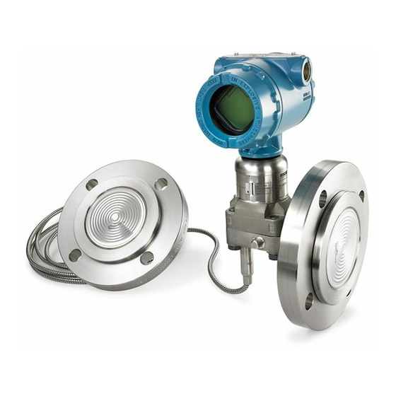
- Page 1 Reference Manual 00809-0100-4002, Rev EA May 2020 ™ Rosemount DP Level Transmitters and 1199 Diaphragm Seal Systems...
- Page 2 Do not attempt to loosen or remove flange bolts while the transmitter is in service. Replacement equipment or spare parts not approved by Emerson for use as spare parts could reduce the pressure retaining capabilities of the transmitter and may render the instrument dangerous.
- Page 3 WARNING Sensor module and electronics housing Sensor module and electronics housing must have equivalent approval labeling in order to maintain hazardous location approvals. When upgrading, verify sensor module and electronics housing certifications are equivalent. Differences in temperature class ratings may exist, in which case the complete assembly takes the lowest of the individual component temperature classes (for example, a T4/T5 rated electronics housing assembled to a T4 rated sensor module is a T4 rated transmitter.) Physical access Unauthorized personnel may potentially cause significant damage to and/or misconfiguration of end users’...
-
Page 5: Table Of Contents
Reference Manual Contents 00809-0100-4002 May 2020 Contents Chapter 1 Introduction......................7 1.1 Using this manual........................7 1.2 Product recycling/disposal......................7 Chapter 2 Remote Seal Systems....................9 2.1 DP Level and remote seal system measurement................9 2.2 Terminology of system components....................9 2.3 Seal system performance......................10 2.4 Balanced vs. - Page 6 Contents Reference Manual May 2020 00809-0100-4002 3.22 SLS dairy process connection–female thread seal per DIN 11851..........61 3.23 WSP saddle seal........................62 3.24 UCP union connection pipe mount seal..................64 3.25 PMW paper mill sleeve seal...................... 67 3.26 CTW chemical tee seal......................69 3.27 TFS wafer style In-line seal......................70 3.28 WFW flow-thru flanged seal.....................72 Chapter 4...
-
Page 7: Chapter 1 Introduction
Reference Manual Introduction 00809-0100-4002 May 2020 Introduction Using this manual This manual is designed to assist in installing, operating, and maintaining the Rosemount 1199 Diaphragm Seal Systems for Pressure Transmitters and diaphragm seal systems that are part of Rosemount DP Level Transmitters including the Rosemount 3051SAL, Rosemount 3051L and Rosemount 2051L. - Page 8 Introduction Reference Manual May 2020 00809-0100-4002 Rosemount DP Level...
-
Page 9: Remote Seal Systems
Reference Manual Remote Seal Systems 00809-0100-4002 May 2020 Remote Seal Systems DP Level and remote seal system measurement DP Level is a reliable measurement solution for measuring level, density, interface, or mass of a process media inside a tank. Remote seal system measurement is unaffected by agitation, foam, or internal obstacles. Remote diaphragm seals extend limitations due to process conditions such as high and low temperatures, corrosive processes, viscous mediums, and hygienic applications. -
Page 10: Seal System Performance
Remote Seal Systems Reference Manual May 2020 00809-0100-4002 Figure 2-2: FFW Seal and Components A. Process flange B. Diaphragm C. Gasket D. Flushing ring (optional) Seal system performance 2.3.1 Volume temperature effects (process temperature effects) Fill fluids expand or contract with temperature changes, creating a volume change that is absorbed by the diaphragm seal and is seen as back pressure at the transmitter. - Page 11 Reference Manual Remote Seal Systems 00809-0100-4002 May 2020 Note ™ Calculations done in Instrument Toolkit with Silicone 200 fill fluid with Rosemount 3051 Transmitter. Figure 2-3: Back Pressure on Diaphragm Causing Error Note Diaphragm temperature effects decrease as seal size increases. 2.3.2 Density temperature effects (head temperature effects) Density temperature effect is due to the change in specific gravity of the fill fluid caused by...
-
Page 12: Balanced Vs. Tuned-System Assemblies
Remote Seal Systems Reference Manual May 2020 00809-0100-4002 Figure 2-4: Response Time vs. Total Performance Example Note Calculations conducted using Instrument Toolkit. Parameters: Silicone 200 fill fluid, Rosemount 3051CD2 Transmitter, 15 ft. capillary length, 2-in. FFW Seal, and calibrated at 25 °C. Balanced vs. - Page 13 Reference Manual Remote Seal Systems 00809-0100-4002 May 2020 Figure 2-5: Balanced System +3.6 inH Head temperature effect (9.0 mbar) No error Seal temperature effect (Cancels out) +3.6 inH Total temperature effect on system (9.0 mbar) Note Temperature effects were calculated in Instrument Toolkit using a 2-in. (DN 50) FFW seal, Silicone 200, 10 ft.
-
Page 14: Specifying The Right Solution For Vacuum Applications
Transmitter mounting position 2.5.3 Seal system construction for vacuum applications Emerson offers welded-repairable or all-welded vacuum system construction styles on diaphragm seal assembles. The all-welded vacuum construction was designed specifically for vacuum applications. In this construction, the sensor module gaskets are removed and a disk is welded over the sensor isolators. -
Page 15: Diaphragm Weld Types
Reference Manual Remote Seal Systems 00809-0100-4002 May 2020 2.5.5 Fill fluid selection When the process is under vacuum conditions, the fill fluid can vaporize at a lower temperature than when it is under normal atmospheric or greater pressure. Each fill fluid has a specific vapor-pressure curve. - Page 16 Remote Seal Systems Reference Manual May 2020 00809-0100-4002 2.6.2 Seam weld design A seam weld design is used when the upper housing material is different from the diaphragm material. The seam welded design has a hermetic weld at the inner diameter of the diaphragm and a TIG weld at the outer edge.
-
Page 17: Differences Between Electronic Remote Sensors And Capillary Systems
Rosemount model number and calculates the total system performance including expected head and seal temperature effects and system response times. Visit the Emerson website for information on how to obtain and use Instrument Toolkit. Rosemount DP Level... -
Page 18: Rosemount Thermal Range Expander: Proper Use And Applications
Remote Seal Systems Reference Manual May 2020 00809-0100-4002 Rosemount Thermal Range Expander: proper use and applications Figure 2-8: Rosemount Thermal Range Expander A. Intermediate diaphragm B. High temperature fill fluid (viscous) C. Ambient temperature fill fluid The Rosemount Thermal Range Expander increases the application range where DP Level technology can be used by expanding the ambient and process temperature ranges of the system. - Page 19 Reference Manual Remote Seal Systems 00809-0100-4002 May 2020 Figure 2-9: Rosemount Thermal Range Expander Temperature Operating Range Rosemount DP Level...
-
Page 20: Thermal Optimizer: Proper Use And Applications
Remote Seal Systems Reference Manual May 2020 00809-0100-4002 2.10 Thermal optimizer: proper use and applications The thermal optimizer keeps fill fluids from gelling in cold ambient temperatures by using high process temperatures to heat the transmitter and capillary. High temperature silicone fill fluid has a low temperature limit in ambient conditions below 32 °F (0 °C). - Page 21 Reference Manual Remote Seal Systems 00809-0100-4002 May 2020 2.10.1 Thermal optimizer limitations Figure 2-10 shows the process and ambient temperature limits for the thermal optimizer with Silicone 704 and Silicone 705 Fill Fluids respectively. The shaded areas represent the temperature limitations; applications outside of the shaded area cannot be used with a thermal optimizer.
- Page 22 Remote Seal Systems Reference Manual May 2020 00809-0100-4002 Rosemount DP Level...
-
Page 23: Chapter 3 Installation
Reference Manual Installation 00809-0100-4002 May 2020 Installation Seal handling and installation 3.1.1 Diaphragm The remote seal diaphragm is designed to withstand pressure and wear from process, but outside of process connection conditions, remote seals are delicate and should be handled with care. - Page 24 Installation Reference Manual May 2020 00809-0100-4002 Figure 3-1: Rosemount 3051SAL with Rosemount Thermal Range Expander Insulation Guidelines Rosemount 3051SAL with Thermal Range Expander Marking: “Do Not Insulate Above this Line” Ok to Do Not Insulate Insulate 3.1.4 Heat tracing When using heat or steam tracing, exercise caution if PVC coating is added onto capillary, as PVC coating should not be exposed to temperatures above 212 °F (100 °C) to avoid the possibility of thermal breakdown.
-
Page 25: Gaskets
Reference Manual Installation 00809-0100-4002 May 2020 Gaskets WARNING When installing remote seal systems which employ a gasket or a gasket and flushing connection ring, make sure the gasket is aligned properly on the gasket sealing surface. The user is responsible to ensure the gasket used does not exceed the temperature limits of the process. -
Page 26: Tagging
Installation Reference Manual May 2020 00809-0100-4002 Table 3-1: Gasket Materials (continued) Seal type Gaskets No gasket is supplied No gasket is supplied Specialty seals Klinger C-4401 Barium-Sulfate filled PTFE O-ring No gasket is supplied No gasket is supplied Klinger C-4401 Use EHEDG approved gasket for EHEDG conformity. -
Page 27: Torque Sequence
Reference Manual Installation 00809-0100-4002 May 2020 Figure 3-4: Rosemount 2051 Sample Label 3.3.1 Max working pressure The maximum working pressure (MWP) of the seal system assembly is stamped on the transmitter neck tag. This can be dependent upon the maximum pressure rating of the seal system or transmitter upper range limit. -
Page 28: Ffw Flush Flanged Seal
Installation Reference Manual May 2020 00809-0100-4002 FFW flush flanged seal Figure 3-6: FFW Two-Piece Design (Shown with Optional Flushing Ring) Standard expanded A. Alignment clamp (option code SA) B. Process flange C. Diaphragm D. Flushing ring (optional) E. Connection to transmitter F. - Page 29 • Gasket (end-user-supplied) Note Flushing rings include an Emerson-supplied gasket. If an alignment clamp is used, a Phillips or slotted screwdriver is required for installation Verify the gasket materials are appropriate for the application. Inspect bolts to ensure the material is compatible with industry standards per the application such as ASME PCC-1.
- Page 30 Step 3. Assemble the flushing ring, Emerson-supplied gasket, and remote seal together. If using an alignment clamp (option code SA) attach the flushing ring to the remote seal. Place the alignment clamp in the machined groove on both the remote seal and the flushing ring. Using the applicable screwdriver, tighten the screw on the clamp to hold the flushing ring in place.
-
Page 31: Rfw Remote Flanged Seal
Reference Manual Installation 00809-0100-4002 May 2020 RFW remote flanged seal Figure 3-8: RFW Standard Design A. Process flange B. Diaphragm C. Lower housing or flushing ring D. Connection to transmitter E. Flushing connection Note Lower housing always required for RFW remote flanged seal. Figure 3-9: RFW Stud Bolt Design A. - Page 32 • Gasket (remote seal to lower housing) (Emerson-supplied) Note Typically, the stud bolt design includes Emerson-supplied stud bolts. Verify the gasket material is appropriate for the application. Inspect bolts to ensure the material is compatible with industry standards per the application such as ASME PCC-1.
- Page 33 3. Assemble the flushing ring, Emerson-supplied gasket, and remote seal together. Place the Emerson-supplied gasket inside the recessed cavity within the flushing ring which is designed to hold the gasket in place.
-
Page 34: Efw Extended Flanged Seal
6. Remove the protective cover from the diaphragm of the remote seal. Use extreme caution during installation to ensure the diaphragm is not damaged. 7. Assemble the remote seal, Emerson-supplied gasket, and lower housing. Place the Emerson-supplied gasket inside the recessed cavity within the lower housing which is designed to hold the gasket in place. - Page 35 Reference Manual Installation 00809-0100-4002 May 2020 3.7.1 Parts required for installation The parts required to install the EFW extended flanged seal will be defined here. Prior to installation, you will need the following: • Torque wrench • Mounting hardware (end-user-supplied) •...
-
Page 36: Pfw Pancake Seal
3.8.2 Process flange Emerson offers the option of supplying the process flange, otherwise the process flange is furnished by the end-user. There is a 5/16–24 threaded connection on the back of the PFW pancake seal. For certain pancake seal assemblies, the Emerson-supplied process flange has a machined hole through the center of the flange that corresponds to the threaded connection in the back of the pancake seal. - Page 37 • Gasket (end-user-supplied) Note Flushing rings include an Emerson-supplied gasket. If an alignment clamp is used, a Phillips or slotted screwdriver is required for installation. Verify the gasket materials are appropriate for the application. Inspect bolts to ensure the material is compatible with industry standards per the application such as ASME PCC-1.
-
Page 38: Fcw Flush Flanged Seal-Ring Type Joint (Rtj) Gasket Surface
Installation Reference Manual May 2020 00809-0100-4002 6. Insert end-user-supplied bolts in the top two bolt holes of the flange on the remote seal. Secure with nuts and hand-tighten. 7. Using a torque wrench on the nut, tighten the assembly in a cross-pattern to ensure even installation (Torque sequence). - Page 39 Reference Manual Installation 00809-0100-4002 May 2020 Inspect bolts to ensure the material is compatible with industry standards per the application such as ASME PCC-1. 3.9.2 Installation steps Follow these steps to install the FCW flush flanged seal with RTJ gasket surface on an existing process flange: Procedure 1.
-
Page 40: Rcw Remote Flanged Seal - Ring Type Joint (Rtj) Gasket Surface
Installation Reference Manual May 2020 00809-0100-4002 3.10 RCW remote flanged seal - ring type joint (RTJ) gasket surface Figure 3-13: RCW Flanged Remote Seal RTJ and Flushing Connection Ring A. Upper housing B. Diaphragm C. Lower housing or flushing ring D. - Page 41 6. Remove the protective cover from the diaphragm of the remote seal. Use extreme caution during installation to ensure the diaphragm is not damaged. 7. Assemble the remote seal, Emerson-supplied gasket, and lower housing. Place the Emerson-supplied gasket inside the recessed cavity within the lower housing which is designed to hold the gasket in place.
-
Page 42: Fuw Flush Flanged Groove Type Seals
Installation Reference Manual May 2020 00809-0100-4002 WARNING Failure to properly install the gasket may cause process leaks, which can result in death or serious injury. 8. Install the bolts in a cross pattern and hand-tighten. 9. Using a torque wrench on the bolt, tighten the assembly in a cross-pattern to ensure even installation (Torque sequence). -
Page 43: Fvw Flush Flanged Tongue Type Seals
Reference Manual Installation 00809-0100-4002 May 2020 3.11.2 Installation steps Follow these steps to install the FUW flush flanged groove type seal on an existing process flange: Procedure 1. Remove the protective cover from the diaphragm of the remote seal. Use extreme caution during installation to ensure the diaphragm is not damaged. - Page 44 Installation Reference Manual May 2020 00809-0100-4002 3.12.1 Parts required for installation The parts required to install the FVW flush flanged tongue type seal will be defined here. Prior to installation, you will need the following: • Torque wrench • Mounting hardware (end-user-supplied) •...
-
Page 45: Rtw Remote Threaded Type Seals
Reference Manual Installation 00809-0100-4002 May 2020 3.13 RTW remote threaded type seals Figure 3-16: RTW Threaded Seal A. Upper housing B. Diaphragm C. Lower housing or flushing ring D. Connection to transmitter Note A lower housing is always required for the RTW type seal. Table 3-4: RTW Upper Housing Torque Values Material (nuts and bolts) Bolt thread size... - Page 46 3. Remove the protective cover from the diaphragm of the remote seal. Use extreme caution during installation to ensure the diaphragm is not damaged. 4. Place the Emerson-supplied gasket into the groove of the lower housing. 5. Place the remote seal on top of the gasket ensuring alignment with the lower housing groove.
-
Page 47: Hts Male Threaded Seal
Reference Manual Installation 00809-0100-4002 May 2020 Note RTW remote threaded type seals with a 10,000 PSI pressure rating are supplied with carbon steel bolts only. 3.14 HTS male threaded seal Figure 3-17: HTS Male Threaded Seal A. Connection to transmitter B. -
Page 48: Scw Hygienic Tri-Clover Tri Clamp Seals
Installation Reference Manual May 2020 00809-0100-4002 3.14.2 Installation steps Follow these steps to install the HTS remote threaded seal on an existing process flange: Procedure 1. Remove the protective cover from the diaphragm of the remote seal. Use extreme caution during installation to ensure the diaphragm is not damaged. 2. - Page 49 00809-0100-4002 May 2020 3.15.1 Clamp and gasket The clamp is furnished by the end-user with the exception of an optional Emerson- ™ supplied high pressure Ladish clamp. Maximum pressure rating of the system is dependent upon the clamp pressure rating.
- Page 50 Installation Reference Manual May 2020 00809-0100-4002 3.15.3 Installation steps Follow these steps to install the SCW hygienic Tri Clamp seal: Procedure 1. Remove the protective cover from the diaphragm of the remote seal. Use extreme caution during installation to ensure the diaphragm is not damaged. 2.
-
Page 51: Ssw Hygienic Tank Spud Seal
The parts required to install the SSW hygienic tank spud seal will be defined here. Prior to installation, you will need the following: • O-ring (Emerson-supplied) • Clamp (Emerson-supplied) Cutting and welding equipment required if installing a new tank spud. - Page 52 Failure to properly install the gasket may cause process leaks, which can result in death or serious injury. 5. Insert the SSW hygienic tank spud seal into the tank spud. 6. Attach the Emerson-supplied clamp and hand-tighten the connection. 3.16.3 Tank preparation When preparing the tank, ensure an area with a minimum diameter of 9¼-in.
- Page 53 Reference Manual Installation 00809-0100-4002 May 2020 Figure 3-21: Bevel Example A. Tank spud B. Bevel C. Tank The flat area should be large enough to minimize spud distortion but small enough so that tank weld requirements can be met. Minimizing the bevel angle will decrease the amount of fill required during weld and minimize the number of weld passes.
- Page 54 Installation Reference Manual May 2020 00809-0100-4002 Figure 3-23: Welding Sections Allow time to cool between weld sections. Weld should be cooled to 350 °F (177 °C) or less after each pass while being cool to the touch is preferred. Use of a damp cloth or compressed air is allowed if rapid cooling is desired.
-
Page 55: Stw Hygienic Thin Wall Tank Spud Seal
3. Remove the protective cover from the diaphragm of the remote seal. Use extreme caution during installation to ensure the diaphragm is not damaged. 4. Place the Emerson-supplied O-ring onto the groove. Failure to properly install the gasket may cause process leaks, which can result in death or serious injury. -
Page 56: Ees Hygienic Flanged Tank Spud Extended Seal
3. Remove the protective cover from the diaphragm of the remote seal. Use extreme caution during installation to ensure the diaphragm is not damaged. 4. Insert end-user-supplied bolts in the bottom two bolt holes of the flange on the remote seal. 5. Place the Emerson-supplied O-ring onto the groove. Rosemount DP Level... -
Page 57: Vcs Tri Clamp In-Line Seal
Reference Manual Installation 00809-0100-4002 May 2020 WARNING Failure to properly install the gasket may cause process leaks, which can result in death or serious injury. 6. Insert the EES hygienic flanged tank spud extended seal into the tank spud. 7. Using the previously installed bolts, attach the remote seal and gasket to the process connection. - Page 58 Installation Reference Manual May 2020 00809-0100-4002 3.19.2 Installation steps Follow these steps to install the VCS hygienic Tri Clamp seal: Procedure 1. Place the appropriate end-user-supplied gasket for the application on the remote seal. WARNING Failure to properly install the gasket may cause process leaks, which can result in death or serious injury.
-
Page 59: Svs Varivent ® Compatible Hygienic Connection Seal
Reference Manual Installation 00809-0100-4002 May 2020 ® 3.20 SVS VARIVENT compatible hygienic connection seal Figure 3-27: SVS VARIVENT Compatible Connection Seal A. Connection to transmitter B. Diaphragm 3.20.1 Parts required for installation The parts required to install the SVS VARIVENT seal will be defined here. Prior to installation, you will need the following: •... -
Page 60: Shp Hygienic Cherry-Burrell ® "I" Line Seal
Installation Reference Manual May 2020 00809-0100-4002 Note EHEDG requirement on T-stub installations: the length (L) divided by the diameter (D) of the tee is to be less than 1 (i.e. L /D < 1). ® 3.21 SHP hygienic Cherry-Burrell “I” line seal Figure 3-28: SHP Cherry-Burrell “I”... -
Page 61: Sls Dairy Process Connection-Female Thread Seal Per Din 11851
Reference Manual Installation 00809-0100-4002 May 2020 Procedure 1. Remove the protective cover from the diaphragm of the remote seal. Use extreme caution during installation to ensure the diaphragm is not damaged. 2. Place the appropriate gasket for the application on the remote seal. WARNING Failure to properly install the gasket may cause process leaks, which can result in death or serious injury. -
Page 62: Wsp Saddle Seal
Installation Reference Manual May 2020 00809-0100-4002 Procedure 1. Remove the protective cover from the diaphragm of the remote seal. Use extreme caution during installation to ensure the diaphragm is not damaged. 2. Place the appropriate gasket for the application on the remote seal. WARNING Failure to properly install the gasket may cause process leaks, which can result in death or serious injury. - Page 63 Reference Manual Installation 00809-0100-4002 May 2020 • Torque wrench • Mounting hardware (Emerson-supplied) • Gasket (Emerson-supplied) Cutting and welding equipment required if installing a new saddle lower. Verify the gasket material is appropriate for the application. Rosemount DP Level...
-
Page 64: Ucp Union Connection Pipe Mount Seal
Installation Reference Manual May 2020 00809-0100-4002 3.23.2 Installation steps Follow these steps to install the WSP saddle seal: Procedure 1. Prepare the tank and weld the saddle lower onto the tank per plant procedures. Ensure the saddle lower is not assembled to the pressure transmitter and/or the remote seal prior to welding. - Page 65 The parts required to install the UCP union connection seal will be defined here. Prior to installation, you will need the following: • Torque wrench • Gasket (Emerson-supplied) Cutting and welding equipment required if installing a new lower housing. Verify the gasket material is appropriate for the application. 3.24.2 Installation steps...
- Page 66 Installation Reference Manual May 2020 00809-0100-4002 contributor to spud distortion due to additional heat input and added filler material in beveled area of hole. Figure 3-32: Installing the Weld Spud Preparing the vessel hole Welding sequence 2.37 (60) A. 100–125 A recommended B.
-
Page 67: Pmw Paper Mill Sleeve Seal
The parts required to install the PMW paper mill seal will be defined here. Prior to installation, you will need the following: • Torque wrench • Gasket (Emerson-supplied) Cutting and welding equipment required if installing a new lower housing. Verify the gasket material is appropriate for the application. 3.25.2 Installation steps... - Page 68 Installation Reference Manual May 2020 00809-0100-4002 minimize the number of weld passes. These best practices will decrease heat input and help mitigate distortion. 3. Position the weld spud in the vessel hole, place heat sink and tack the housing in place using the welding sequence shown in Figure 3-34.
-
Page 69: Ctw Chemical Tee Seal
Reference Manual Installation 00809-0100-4002 May 2020 5. Remove the protective cover from the diaphragm of the remote seal. Use extreme caution during installation to ensure the diaphragm is not damaged. 6. Place the O-rings onto the seal body. WARNING Failure to properly install the gasket may cause process leaks, which can result in death or serious injury. -
Page 70: Tfs Wafer Style In-Line Seal
Installation Reference Manual May 2020 00809-0100-4002 Procedure 1. Remove the protective cover from the diaphragm of the remote seal. Use extreme caution during installation to ensure the diaphragm is not damaged. 2. Place the appropriate end-user-supplied gasket on the remote seal. WARNING Failure to properly install the gasket may cause process leaks, which can result in death or serious injury. - Page 71 Reference Manual Installation 00809-0100-4002 May 2020 Verify the gasket material is appropriate for the application. Inspect bolts to ensure the material is compatible with industry standards per the application such as ASME PCC-1. 3.27.2 Installation steps Follow these steps to install the TFS wafer style In-line seal on an existing flanged process connection: Procedure 1.
-
Page 72: Wfw Flow-Thru Flanged Seal
• Gasket (lower housing to process flange) (end-user-supplied) • Gasket (remote seal to lower housing) (Emerson-supplied) Verify the gasket material is appropriate for the application. Inspect bolts to ensure the material is compatible with industry standards per the application such as ASME PCC-1. - Page 73 8. Remove the protective cover from the diaphragm of the remote seal. Use extreme caution during installation to ensure the diaphragm is not damaged. 9. Assemble the remote seal, Emerson-supplied gasket, and lower housing. Failure to properly install the gasket may cause process leaks, which can result in death or serious injury.
- Page 74 Installation Reference Manual May 2020 00809-0100-4002 Rosemount DP Level...
-
Page 75: Chapter 4 Configuration
Reference Manual Configuration 00809-0100-4002 May 2020 Configuration Calculating range points 4.1.1 Remote seals Calculating range points • Open tank (zero based) • Open tank (non-zero based) • Closed tank (non-zero based) Transmitters installation best practice • Open tank (zero based) •... - Page 76 Configuration Reference Manual May 2020 00809-0100-4002 4.1.2 Zero-based lower range value Figure 4-2: Remote Capillary and Direct Mount Remote capillary Direct mount ATM = open to atmosphere vertical distance from transmitter to high pressure seal vertical distance from transmitter to low pressure seal = the maximum level of process above the high pressure seal and typically the 20 mA lower range value = the minimum level of process above the high pressure seal and typically the 4 mA lower...
- Page 77 Reference Manual Configuration 00809-0100-4002 May 2020 4.1.3 Non-zero based lower range value Figure 4-3: Remote Capillary ATM = open to atmosphere vertical distance from transmitter to high pressure seal vertical distance from transmitter to low pressure seal = the maximum level of process above the high pressure seal and typically the 20 mA lower range value = the minimum level of process above the high pressure seal and typically the 4 mA lower range value...
- Page 78 Configuration Reference Manual May 2020 00809-0100-4002 4.1.4 Non-zero based lower range value (transmitter mounted above seal) Figure 4-4: Remote Capillary ATM = open to atmosphere vertical distance from transmitter to high pressure seal vertical distance from transmitter to low pressure seal = the maximum level of process above the high pressure seal and typically the 20 mA lower range value = the minimum level of process above the high pressure seal and typically the 4...
- Page 79 Reference Manual Configuration 00809-0100-4002 May 2020 4.1.5 Non-zero based lower range value (Tuned-System assembly) ™ Figure 4-5: Tuned-System 108 in. SG = 0.934 d = 120 in. SG = 0.75 0 in. vertical distance from transmitter to high pressure seal vertical distance from transmitter to low pressure seal = the maximum level of process above the high pressure seal and typically the 20 mA lower range value...
- Page 80 Configuration Reference Manual May 2020 00809-0100-4002 4.1.6 Non-zero based lower range value (balanced system with transmitter between seals) Figure 4-6: Balanced System 108 in. d = 60 in. SG = 0.75 SG = 0.934 d = -60 in. 0 in. vertical distance from transmitter to high pressure seal vertical distance from transmitter to low pressure seal = the maximum level of process above the high pressure seal and typically the 20...
- Page 81 Reference Manual Configuration 00809-0100-4002 May 2020 4.1.7 Non-zero based lower range value(balanced system with transmitter below seals) Figure 4-7: Remote Capillary 108 in. d = 180 in. SG = 0.75 (60 +120) 0 in. d = 60 in. SG = 0.934 vertical distance from transmitter to high pressure seal vertical distance from transmitter to low pressure seal = the maximum level of process above the high pressure seal and typically the 20...
-
Page 82: Dp Level Transmitter Installation Best Practices
Configuration Reference Manual May 2020 00809-0100-4002 DP Level transmitter installation best practices Pressure transmitters have a sensor module with a primary fill fluid. Therefore, the mounting position of a standard transmitter with silicon fill could read approx ±1.25 inH worst case after installation. This is simply zeroed out using a Field Communicator after installation so that it will read zero pressure. - Page 83 Reference Manual Configuration 00809-0100-4002 May 2020 4.2.2 Closed tank (non-zero based) For closed tank level applications, this value is most likely too high and cannot be zeroed out due to the applied pressure of the secondary fill fluid. For this reason, the transmitter would simply be re-ranged so that the 0% value (4 mA) would equal the installed value.
- Page 84 Configuration Reference Manual May 2020 00809-0100-4002 Figure 4-10: Before Zero Trim Using Field Communicator Figure 4-11: After Zero Trim Using Field Communicator Rosemount DP Level...
- Page 85 Reference Manual Configuration 00809-0100-4002 May 2020 4.2.4 Closed tank example (non-zero based lower range value) Note ™ For F Fieldbus, refer to the AI Function Blocks in reference manual. OUNDATION Figure 4-12: Tuned-System Procedure 1. Set seals at the same elevation for bench pressure verification, if required to range transmitter.
- Page 86 Configuration Reference Manual May 2020 00809-0100-4002 4 mA = 0 inH 20 mA = 81 inH After installing and pushing the Zero button, the transmitter will now be ranged per example from Figure 4-5: 4 mA = –112.08 inH 20 mA = –31.08 inH Note If you have a Field Communicator device connected when the Zero button is pushed, you must re-boot the Field Communicator to see the change.
- Page 87 Reference Manual Configuration 00809-0100-4002 May 2020 4 mA = 0 inH 20 mA = 81 inH After mounting transmitter, the pressure reads –112.08 inH O, see Figure 4-14. Using a Field Communicator, re-range the transmitter, see Figure 4-14. The transmitter will now be ranged per example from Figure 4-5: 4 mA = –112.08 inH...
- Page 88 Configuration Reference Manual May 2020 00809-0100-4002 Note Depending on the HART device (Field Communicator/AMS Wireless Configurator) DD the following steps may be slightly different. For the Rosemount 3051S, in the HART menu tree, go to the Scaled variable Config (under guided set up).
-
Page 89: Chapter 5 Fill Fluids
5.1.2 Testing Emerson’s vapor pressure curves are derived from empirical lab testing in real devices at both vacuum conditions and at the maximum continuous temperature at one atmosphere of pressure. The maximum continuous temperature at one atm of pressure correlates to the thermal stability of the fill fluid, which is the maximum temperature the fill fluid will remain in its original molecular form. -
Page 90: Fill Fluid Vapor Pressure Curves
If the fill fluid vaporizes, the seal system is permanently damaged. Emerson offers numerous types of fill fluids for remote seal systems, each fill fluid has a specific vapor-pressure curve. - Page 91 Reference Manual Fill Fluids 00809-0100-4002 May 2020 Note Fill fluids can operate at lower temperatures than their shaded section shown in Figure 5-2. For exact minimum operating temperatures, consult the Rosemount DP Level Fill Fluid Specifications Technical Note. Figure 5-2: Vapor Pressure Curves of General Use Fill Fluids 5.3.2 Fill fluid selection example In an application that has a maximum process temperature of 284 °F (140 °C) and a...
- Page 92 Fill Fluids Reference Manual May 2020 00809-0100-4002 Rosemount DP Level...
-
Page 93: Maintenance And Troubleshooting
Reference Manual Maintenance and Troubleshooting 00809-0100-4002 May 2020 Maintenance and Troubleshooting Cleaning Avoid using abrasive agents or high pressure water jets when cleaning the remote seals. Troubleshooting Remote seal systems are factory filled systems that cannot be refilled in the field. Do not attempt to disconnect the seals or capillaries from the transmitter. - Page 94 Maintenance and Troubleshooting Reference Manual May 2020 00809-0100-4002 Potential cause Cold temperature Recommended actions Fill fluid viscosity is temperature dependent. Less viscous fill fluid enhances time response. Heat traced capillaries can be added as an option to maintain constant temperatures to fill fluid. 6.2.3 Drifting Potential cause...
-
Page 95: Return Of Materials
Material Safety Data Sheet (MSDS) for each hazardous substance identified must be included with the returned goods. Service support To expedite the return process outside of the United States, contact the nearest Emerson representative. Within the United States, call the Emerson Instrument and Valves Response Center using the 1-800-654-RSMT (7768) toll-free number. - Page 96 Maintenance and Troubleshooting Reference Manual May 2020 00809-0100-4002 Rosemount DP Level...
-
Page 97: Reference Data
Product certifications To view current product certification, follow these steps: Procedure 1. Go to the product page on Emerson.com/Rosemount-1199. 2. Scroll as needed to the green menu bar and click Documents & Drawings. 3. Click Manuals & Guides. 4. Select the appropriate Quick Start Guide. - Page 98 Reference data Reference Manual May 2020 00809-0100-4002 Table 7-1: Flush Flanged (FFW) and Pancake (PFW) Lower Housings (continued) Material Size Part number One ¼-in. Two ¼-in. One ½-in. Two ½-in. DN 80 DP0002-8111-HC DP0002-8121-HC DP0002-8112-HC DP0002-8122-HC Alloy 400 2-in. DP0002-2111-M4 DP0002-2121-M4 DP0002-2112-M4 DP0002-2122-M4...
- Page 99 Reference Manual Reference data 00809-0100-4002 May 2020 Table 7-5: Remote Flanged (RFW) Lower Housings Material Size Part number No flushing One ¼-in. Two ¼-in. One ½-in. Two ½-in. connection 316 SST 1-in. DP0004-1100- DP0004-1111- DP0004-1121- DP0004-1112- DP0004-1122- 1½-in. DP0004-1600- DP0004-1611- DP0004-1621- DP0004-1612- DP0004-1622-...
- Page 100 Reference data Reference Manual May 2020 00809-0100-4002 Table 7-6: Gaskets for Remote Flanged (RFW) Lower Housings (continued) Material Size Part number C4401 Aramid PTFE Barium sulfate GHB GRAFOIL Ethylene fiber filled PTFE propylene 1½-in. DP0007-2401- DP0007-2401- DP0007-2401- DP0007-2401- DP0007-2401- DN 25 DP0007-2401- DP0007-2401- DP0007-2401-...
- Page 101 Reference Manual Reference data 00809-0100-4002 May 2020 Table 7-8: Threaded (RTW) Lower Housings (continued) Material Size Part number One ¼-in. Two ¼-in. One ½-in. Two ½-in. No flushing connection ¾–14 NPT DP0070-1401- DP0070-1412- DP0070-1422- DP0070-141A- DP0070-142A- 1–11.5 NPT DP0070-1501- DP0070-1512- DP0070-1522- DP0070-151A- DP0070-152A-...
- Page 102 Reference data Reference Manual May 2020 00809-0100-4002 Table 7-8: Threaded (RTW) Lower Housings (continued) Material Size Part number One ¼-in. Two ¼-in. One ½-in. Two ½-in. No flushing connection 1½–11.5 DP0070-1701- G½A DIN DP0070-1901- DP0070-1912- DP0070-1922- DP0070-191A- DP0070-192A- 16288 Table 7-9: Gaskets for Threaded (RTW) Lower Housings Size Part number C4401...
- Page 103 Reference Manual Reference data 00809-0100-4002 May 2020 Table 7-11: Sanitary Tank Spud Seal (SSW) Parts (continued) Part description Part number Ethylene Propylene O-ring 01199-7001-0003 Table 7-12: Sanitary Tri Clamp Seal (SCW and VCS) Parts Part description Part number ¾-in. 01199-0035-0105 1½-in.
- Page 104 Emerson Terms and Conditions of Sale are available upon request. The Emerson logo is a Facebook.com/Rosemount trademark and service mark of Emerson Electric Co. Rosemount is a mark of one of the Youtube.com/user/RosemountMeasurement Emerson family of companies. All other marks are the property of their respective owners.