- 1 SAFETY INFORMATION
- 2 SET UP & USE
- 3 CLEANING & CARE
- 4 TROUBLESHOOTING & WARRANTY
- 5 Documents / Resources
SAFETY INFORMATION

DANGER - Immediate hazards which WILL result in severe personal injury or death

WARNING - Hazards or unsafe practices which COULD result in severe personal injury or death

CAUTION - Hazards or unsafe practices which COULD result in minor personal injury
IMPORTANT SAFETY INSTRUCTIONS
When using electrical appliances, basic safety precautions should be followed, including the following

HANDLING ALKALINE BATTERIES
When handling alkaline batteries, basic safety precautions should be followed, including the following
SAVE THESE INSTRUCTIONS
HOUSEHOLD USE ONLY
GROUNDING INSTRUCTIONS
ELECTRICAL REQUIREMENTS
In the event of malfunction or breakdown, grounding provides a path of least resistance for electric current to reduce the risk of electric shock. The appliance must be connected to a cord having an equipmentgrounding conductor and a grounding plug. The plug must be plugged into an appropriate outlet that is properly installed and grounded in accordance with all local codes and ordinances.
Improper connection of the equipment grounding conductor can result in a risk of electric shock. The conductor with insulation having an outer surface that is green with or without yellow stripes is the equipment grounding conductor. If repair or replacement of the cord or plug is necessary, do not connect the equipment-grounding conductor to a live terminal. Check with a qualified electrician or service person if the grounding instructions are not completely understood, or if in doubt as to whether the appliance is properly grounded. Do not modify the plug connected to the appliance – if it will not fit the outlet, have a proper outlet installed by a qualified electrician.
FOR GROUNDED, CORD-CONNECTED APPLIANCE RATED LESS THAN15A AND INTENDED FOR USE ON A NOMINAL 120V SUPPLY CIRCUIT
The appliance is for use on a nominal 120V circuit and should be connected to a grounding outlet that looks like the one illustrated below. The use of a temporary adaptor is not recommended. 
LCDI POWER CORD AND PLUG
This air conditioner is equipped with an LCDI (Leakage Current Detection and Interruption) power cord that is required by UL. This power supply cord contains state-of-the-art electronics that sense leakage current. If the cord is damaged and leakage occurs, power will be disconnected from the unit.
The test and reset buttons on the LCDI Plug are used to check if the plug is functioning properly.
Test LCDI before each use.
To test the plug:
NOTES:
- Always make sure the reset button is pushed in for correct operation
![]()
- It must be replaced by one obtained from the product manufacturer.


RISK OF FIRE
It is important the plug fits tightly into the wall outlet. If the plug does not fit securely and appears loose, it should not be used. Have a licensed electrician replace the receptacle.
SAFETY GUIDELINES
To prevent injury to the user or other people and property damage, the following instructions must be followed. Incorrect operation due to ignoring of instructions may cause harm or damage.
| ALWAYS DO THIS | NEVER DO THIS | ENERGY SAVE |
|
|
6,000 BTU up to 250 sq. ft. 8,000 BTU up to 350 sq. ft. 10,000 BTU up to 450 sq. ft. |
OPERATING CONDITION
The air conditioner must be operated within the temperature range indicated below:
NOTE: Unit performance may be affected when in use outside of these operating temperatures.
| MODE | ROOM TEMPERATURE |
| COOL | 64˚F (18˚C) ~ 95˚F (35˚C) |
| DEHUMIDIFY | 64˚F (18˚C) ~ 95˚F (35˚C) |
| HEAT (ELECTRICAL HEAT TYPE) | 45˚F (7°C) ~ 81˚F (27˚C) |
SET UP & USE
PARTS & FEATURES

Hose outlet and inlet are pre-assembled to the hose 

SPECIFICATIONS
BPP05WTB
Unit dimensions (W x D x H): 17.32" x 14.05" x 27.16"
Unit Weight approx. 51.1 lbs.
BPP06WTB
Unit dimensions (W x D x H): 17.32" x 14.05" x 27.16"
Unit Weight approx. 54.8 lbs.
BPP08WTB
Unit dimensions (W x D x H): 17.32" x 14.05" x 27.16"
Unit Weight approx. 63.1 lbs.
BPP08HWTB
Unit dimensions (W x D x H): 17.32" x 14.05" x 27.16"
Unit Weight approx. 64.5 lbs.
BPP10WTB
Unit dimensions (W x D x H): 17.32" x 14.05" x 27.16"
Unit Weight approx. 65.1 lbs.
BPP10HWTB
Unit dimensions (W x D x H): 17.32" x 14.05" x 27.16"
Unit Weight approx. 66.6 lbs.
Electric Requirements: 115V ~ 60Hz
INSTALLATION GUIDE
LOCATION
SUGGESTED TOOLS FOR WINDOW KIT INSTALLATION
WINDOW SLIDER KIT INSTALLATION
Your window slider kit has been designed to fit most standard "Vertical" and "Horizontal" window applications; however, it may be necessary for you to improvise/modify some aspect of the installation procedures for certain types of window. Minimum and maximum window openings:
MAXIMUM : 47.2" (120 cm)
MINIMUM : 27.5" (70 cm)
NOTE: Adjust the length of the window slider kit according to the window width or height, and secure it with the provided locking screws.
NOTE: If the window opening is less than 27.5" the minimum length of the window slider kit, cut the one with a hole in it short to fit for the window opening. Never cut out the hole in window slider kit.
Horizontal Window 
Vertical Window 
Window Slider Kit 

DOUBLE-HUNG SASH/SLIDING CASEMENT WINDOW INSTALLATION

EXHAUST HOSE INSTALLATION
The air exhaust hose and hose inlet must be installed or removed from the portable air conditioner in accordance with the way it is being used:
COOL, DEHUMIDIFY, HEAT (Heat models BPP08HWTB and BPP10HWTB only: Air exhaust hose and hose inlet should be connected to the portable air conditioner.
FAN: Air exhaust hose and hose inlet should be disconnected from the portable air conditioner.
- Connect hose outlet to other end of air exhaust hose. Push hose outlet over the end of the hose, push in slightly and then start threading it on in a clockwise direction. (see Fig. 2)

- Align the tabs on the hose inlet into the slots over the air outlet, insert and push down. (see Fig. 3)

- Affix the hose outlet into the window slider kit and seal. (Fig. 4 & 5)


NOTE: The exhaust hose can be compressed or extended moderately, but it is desirable to keep the length to a minimum. Also make sure that the hose does not have any sharp bends.
CONTROL PANEL

Pictures are for illustration purpose only. Your model may or may not have all the features.
OPERATING FROM THE CONTROL PANEL
The Control Panel enables you to manage all the main functions of the appliance, but to fully exploit its potential, you must use the remote control.
TURNING THE APPLIANCE ON
- Press the
![]() button until the appliance comes on. The last function active when it was turned off will appear.
button until the appliance comes on. The last function active when it was turned off will appear.
* Never turn the air conditioner off by unplugging from the outlet. Always press the button  , then wait for a few minutes before unplugging. This allows the appliance to perform a cycle of checks to verify operation.
Note: Before pressing Power On button make sure the condensate drain plug in the rear of the unit is securely in place to avoid any leaking.
- Press the MODE
![]() button until the light corresponding to the required Mode lights up.
button until the light corresponding to the required Mode lights up.
 button until the light corresponding to the required Mode lights up.
COOL

DEHUMIDIFY

FAN

HEAT
Heat models BPP08HWTB and BPP10HWTB only
COOL MODE
 Ideal for hot weather when you need to cool the room. To set operation of the appliance correctly, press the + or – buttons until the desired temperature is displayed. (See Fig. 7)
Then select the fan speed by pressing the Fan Speed Button until the light corresponding to the required fan speed lights up:
 HIGH: The Fan operates at maximum to reach the required temperature as rapidly as possible.
 MED: Reduces Fan noise level but still maintains cooling.
 LOW: For quiet operation.
DEHUMIDIFY
 Press the "MODE" button until the "DEHUMIDIFY" indicator light comes on.
DRAINING IN DEHUMIDIFICATION MODE
- FULL TANK
![]() - When the water level reaches a predetermined level, the "full tank" indicator light goes on. The unit will have to be drained.
- When the water level reaches a predetermined level, the "full tank" indicator light goes on. The unit will have to be drained.
 - When the water level reaches a predetermined level, the "full tank" indicator light goes on. The unit will have to be drained.
 NOTE: Refer to Water Drainage section.
FAN MODE
HEAT MODE (Heat models BPP08HWTB and BPP10HWTB only)
 Press the "MODE" button until the "HEAT" indicator light comes on.
- Press the + or – buttons to select your desired room temperature. The temperature can be set within a range of 61°F-88°F.
NOTE: At the beginning of this mode, you may have to wait a few seconds before the appliance starts to give out hot air.
TIMER
- Press the + or – button to select the AUTO TIME by 1 hour increments, up to 24 hours. The LED Display will indicate the remaining time. Press the TIMER button again. The TIMER indicator light illuminates to show that the AUTO STOP program is initiated.
- Press the + or – button to select the AUTO TIME by 1 hour increments, up to 24 hours. The LED Display will indicate the remaining time. Press the TIMER button again. The TIMER indicator light illuminates to show that the AUTO START program is initiated.
SWING INDICATOR LIGHT
 When this light is illuminated, it indicates that the air swing is activated from the remote and the louvers will move up and down.
SLEEP INDICATOR LIGHT
 When this light is illuminated, it indicates that SLEEP has been activated from the remote control and that the temperature will gradually adjust.
OPERATING FROM THE REMOTE CONTROL
BATTERY INSTALLATION (BATTERIES NOT INCLUDED)

Use only AAA or IEC R03 1.5V alkaline batteries. Remove the batteries if the remote is not used for a month or longer. Do not attempt to recharge the batteries. Both batteries should be replaced at the same time. Do not dispose of the batteries in a fire as they man explode.
Point the remote control at the receiver on the appliance. The remote control must be no more than 7 meters away from the appliance (without obstacle between the remote control and the receiver).
The remote control must be handled with extreme care. Do not drop it or expose it to direct sun light or sources of heat.
REMOTE CONTROL

POWER BUTTON: Press to Turn ON or OFF
TIMER BUTTON: Used to set a delay start or shut down time.
MODE BUTTON: Each time you press the button COOL, DEHUMIDIFY, FAN, HEAT (models BPP08HWTB and BPP10HWTB is selected)
˚C / ˚F SELECTOR BUTTON: Select Fahrenheit or Celsius.
INCREASE: Increase the temperature setting.
DECREASE: Decrease the temperature setting.
LED BUTTON: Illuminates the LED screen on the unit.
SWING BUTTON: Activates the air swing of the louvers.
FAN SPEED BUTTON: Used to select the HIGH, MED or LOW Fan speed.
SLEEP BUTTON: Gradually adjusts the temperature.
| LED Display Indicators | |||
 |
Cooling mode |
 |
Fan speed |
 |
Dehumidify mode |
 |
Swing |
 |
Fan mode |
 |
Timer on |
 |
Heat mode Heat models BPP08HWTB and BPP10HWTB only |
 |
Time |
 |
Sleep | ||
 |
Display temp. or hours |
 |
Fahrenheit or Celsius. |
POWER BUTTON 
![]() Will show on the remote LED screen when buttons are pressed to show that the remote control is sending a signal to the air conditioner.
Will show on the remote LED screen when buttons are pressed to show that the remote control is sending a signal to the air conditioner.
 Will show on the remote LED screen when buttons are pressed to show that the remote control is sending a signal to the air conditioner.
MODE BUTTON 
- Press the mode button to scroll through COOL
![]() , DEHUMIDIFY
, DEHUMIDIFY ![]() , FAN
, FAN ![]() , HEAT
, HEAT ![]() (Heat models BPP08HWTB and BPP10HWTB only)
(Heat models BPP08HWTB and BPP10HWTB only)
 , FAN
, FAN  (Heat models BPP08HWTB and BPP10HWTB only)
COOL
- Select the target temperature 61˚F – 88˚F (16˚C – 31˚C) by pressing the + or – buttons until the desired temperature is displayed on the LED screen.
- Press the Fan Speed Button
![]() to select Low, Medium, or High Speed.
to select Low, Medium, or High Speed.

DEHUMIDIFY
Ideal for reducing humidity.
Draining in Dehumidify mode
- FULL TANK - When the water level reaches a predetermined level, the "full tank" indicator light goes on. The unit will have to be drained.
NOTE: Refer to Water Drainage section.
FAN
- Press the Fan Speed Button
![]() to select Low, Medium or High Speed.
to select Low, Medium or High Speed.
HEAT
- Select the target temperature 61˚F – 88˚F (16˚C – 31˚C) by pressing the + or – buttons until the desired temperature is displayed on the LED screen.
- Press the speed button to select HIGH, MEDIUM or LOW fan speed.
NOTE: At the beginning of this mode, you may have to wait a few seconds before the appliance starts to give out hot air.
SWING
TIMER
- Press the + or – button to select the AUTO TIME by 1 hour increments, up to 24 hours. The Remote LCD Display will indicate the selected time. Press the TIMER button again to set the selected time. There will be a steady TIME ON/ OFF symbol on the remote LCD display and the TIMER indicator light will be illuminated on the control panel of the unit to show that the AUTO STOP program is initiated.
- Press the + or – button to select the AUTO TIME by 1 hour increments, up to 24 hours. The Remote LCD Display will indicate the selected time. Press the TIMER button again to set the selected time. There will be a steady TIME ON/ OFF symbol on the remote LCD display and the TIMER indicator light will be illuminated on the control panel of the unit to show that the AUTO START program is initiated.
SLEEP 
°C / °F SELECTOR BUTTON
- When the appliance is powered on, press the °C / °F button, then you can select the unit of temperature from Fahrenheit or Celsius.

WATER DRAINAGE FOR COOLING AND HEAT MODES
This air conditioner is equipped with auto water evaporation so the water compartment would not typically fill in cooling or heating mode unless there is high humidity. Water drainage will generally only be required at the end of the season for these modes. (see START-END OF SEASON OPERATIONS).
NOTE: FULL TANK - When the water level reaches a predetermined level, the "full tank" indicator light located on the control panel of the unit goes on. If an error code appears on the display screen on the control panel "E2" in COOL mode or "E4" in HEAT mode. The unit will have to be drained.
Intermittent Draining
- Let the water drain away and replace the drain cap. Restart the machine until the error codes E2 or E4 disappears. If the error repeats, call for service.

NOTE: Be sure to reinstall the bottom drain plug before using the unit.

Continuous Draining

WAIT 3 MINUTES BEFORE RESUMING OPERATION
Continuous Draining for Dehumidification Mode
Unplug the unit from the power source.
Remove the drain cap located in the back center of the unit. While doing this operation some residual water may spill so have a drip pan (not supplied) to collect the water.
Connect the drain hose (supplied) as shown in the diagram. The water can be continuously drained through the hose into a floor drain or bucket.
Turn on the unit.
WAIT 3 MINUTES BEFORE RESUMING OPERATION
CLEANING & CARE
CLEANING
Before cleaning or maintenance, turn the appliance off by pressing the  button on the control panel or button on the remote control. Unplug from the electrical outlet.
CLEANING THE CABINET
You should clean the appliance with a slightly damp cloth then dry with a dry cloth.
CLEANING THE FILTER
To keep your air conditioner working efficiently, you should clean the evaporator filter every week of operation.
The filter is housed in the intake grill.
Use a vacuum cleaner to remove dust accumulations from the filter. If it is very dirty, immerse in warm water and rinse a number of times. The water should be luke warm. After washing, leave the filter to dry then re-insert the filter.
START - END OF SEASON OPERATIONS
START OF SEASON CHECKS
Make sure the power cable and plug are undamaged. Follow the installation instructions precisely.
END OF SEASON OPERATIONS
See Water Drainage section to make sure the air conditioner is completely drained of water.
Clean the filter and dry thoroughly before reinstalling.
TROUBLESHOOTING & WARRANTY
BEFORE YOU CALL FOR SERVICE
IF THE AIR CONDITIONER FAILS TO OPERATE:
IF NONE OF THE ABOVE SOLVES THE PROBLEM, CONTACT A QUALIFIED TECHNICIAN. DO NOT TRY TO ADJUST OR REPAIR THE AIR CONDITIONER YOURSELF. Any person who is involved with working on or breaking into a refrigerant circuit should hold a current valid certificate from an industryaccredited assessment authority, which authorizes their competence to handle refrigerants safely in accordance with an industry recognized assessment specification.
Do not use means to accelerate the defrosting process or to clean other than those recommended by the manufacturer.
Servicing shall only be performed as recommended by the equipment manufacturer. Maintenance and repair requiring the assistance of other skilled personnel shall be carried out under the supervision of the person competent in the use of the flammable refrigerants.
CUSTOMER SERVICE

DO NOT RETURN THIS PRODUCT TO THE STORE
If you have a problem with this product, please contact the BLACK+DECKER Customer Satisfaction Center at 844-299-0879. DATED PROOF OF PURCHASE, MODEL # AND SERIAL # REQUIRED FOR WARRANTY SERVICE

Risk of fire/ flammable materials (Required for R32/R290 units only)

Read this manual carefully before installing or operating your new air conditioning unit. Make sure to save this manual for future reference.
TROUBLESHOOTING
Troubleshoot your problem by using the chart below. If the air conditioner still does not work properly, contact BLACK+DECKER customer service center or the nearest authorized service center. Customers must never troubleshoot internal components.
| TROUBLE | POSSIBLE CAUSE | POSSIBLE REMEDY |
| Unit does not start when pressing ON/OFF button |
|
|
| Not cool enough |
|
|
| Noisy or vibration |
|
|
| Unit does not run and water full indicator light is on. LED display indicates "E2" in COOL mode or "E4" in HEAT mode. |
|
|
| LED display "E0", "E1", "E3" |
|
Contact the Customer Satisfaction Center for assistance with error code. |
| Remote is not working |
|
|
LIMITED WARRANTY
Any repair, replacement, or warranty service, and all questions about this product should be directed to BLACK+DECKER at 844-299-0879 from the USA or Puerto Rico.
BLACK+DECKER warrants to the original purchaser that the product will be free from defects in material, parts and workmanship for the period designated for this product. The warranty commences the day the product is purchased and covers up to a period of 1 year (12 months) for labor/1 year (12 months) for parts (manufacturing defects only).
BLACK+DECKER agrees that it will, at its option, replace the defective product with either a new or remanufactured unit equivalent to your original purchase during the warranty period.
Exclusions:
This warranty does not apply to the below:
REPAIR OR REPLACEMENT AS PROVIDED UNDER THIS WARRANTY IS THE EXCLUSIVE REMEDY OF THE CUSTOMER; BLACK+DECKER. SHALL NOT BE LIABLE FOR ANY INCIDENTAL OR CONSEQUENTIAL DAMAGES FOR BREACH OF ANY EXPRESS OR IMPLIED WARRANTY ON THIS PRODUCT, EXCEPT TO THE EXTENT PROHIBITED BY APPLICABLE LAW. ANY IMPLIED WARRANTY OF MERCHANTABILITY OF FITNESS FOR A PARTICULAR PURPOSE ON THIS PRODUCT IS LIMITED TO THE DURATION OF THE WARRANTY.
Some states do not allow the exclusion or limitations of incidental or consequential damages, or limitations on how long the warranty lasts. In these cases the above exclusions or limitations may not apply to you. This warranty gives you specific legal rights and you may also have other rights which vary from state to state.
Obtaining Service: To obtain service, product literature, supplies or accessories please call 844-299-0879 to create a ticket for exchange/repair. Please make sure to provide the date of purchase, model number and a brief description of the problem. Our customer service representative will contact you or send detailed return instructions.
BLACK+DECKER does not warrant that the appliance will work properly in all environmental conditions, and makes no warranty and representation, either implied or expressed, with respect to the quality, performance, merchantability, or fitness for a particular purpose other than the purpose identified within this user's manual. BLACK+DECKER has made every effort to ensure that this user's manual is accurate and disclaims liability for any inaccuracies or omissions that may have occurred. Information in this user's manual is subject to change without notice and does not represent a commitment on the part of BLACK+DECKER. BLACK+DECKER reserves the right to make improvements to this user's manual and/or to the products described in this user's manual at any time without notice. If you find information in this manual that is incorrect, misleading, or incomplete, please contact us at 844-299-0879.
W Appliance Co.
1356 Broadway
New York, NY 10018
This device complies with part 15 of the FCC rules. Operation is subject to the following two conditions:
- This device must accept any interference received, including interference that may cause undesired operation. This equipment has been tested and found to comply with the limits for a Class B digital device, pursuant to Part 15 of the FCC rules. These limits are designed to provide reasonable protection against harmful interference in a residential installation. This equipment generates, uses and can radiate radio frequency energy and, if not installed and used in accordance with the instructions, may cause harmful interference to radio communications. However, there is no guarantee that the interference will not occur in a particular installation. If this equipment does cause harmful interference to radio or television reception, which can be determined by turning the equipment off and on, the user is encouraged to try to correct the interference by one or more of the following measures:
BLACK & DECKER, BLACK+DECKER, the BLACK & DECKER and BLACK+DECKER logos and product names and the orange and black color scheme are trademarks of The Black & Decker Corporation, used under license. All rights reserved.
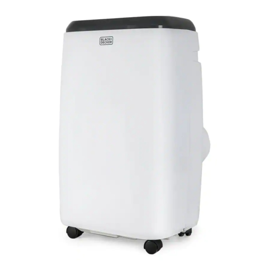
Product in this box may differ slightly from that pictured. Does not affect function. Not all accessories shown in photography are included in this package.
Imported by W Appliance, Inc., 1356 Broadway, New York, NY 10018
January 2021

Documents / ResourcesDownload manual
Here you can download full pdf version of manual, it may contain additional safety instructions, warranty information, FCC rules, etc.
Thank you! Your question has been received!


Need Assistance?
Do you have a question about the BPP05WTB that isn't answered in the manual? Leave your question here.