
Related Manuals for Kenwood CG-931


Summary of Contents for Kenwood CG-931
- Page 1 Color Pattern Generator CG-931 CG-932 INSTRUCTION MANUAL KENWOOD CORPORATION ©PRINTED IN JAPAN...
- Page 2 p r o d u c t K E N W O O D C O R P O R A T I O N 17-5, 2-chome, Shibuya, Shibuya-ku, Tokyo 150, Japan...
-
Page 3: Table Of Contents
CONTENTS 1 . OUTLINE 1. OUTLINE • The CG-931 [CG-932] is a portable color pattern 2. FEATURES • generator for use in the generation of color bar, dot, cross-hatch, and centercross patterns. It is used in the 3. SPECIFICATIONS •... -
Page 4: Features
2. F E A T U R E S • T h e product is a NTSC [PAL] standard format color synchronizing signals can be obtained. pattern generator which enables switching between • T h e device's synchronizing signal includes an equal- full-field and I.Q.W. -
Page 5: Specifications
(See diagram on page 16) V A R + / - 2 0 % + / - 2 0 % CG-931 EIA: RS-189A standard SMPTE: ECR-1-1978 standard CG-932 BARS 1: 2 minute increments BARS 2: 3 minute increments I.Q.W. OFF Full-field color bars [PAL: U . - Page 6 J a p a n U S A Output impedance 75 ohm (MHz) (MHz) (D Sub-carrier Wave CG-931: 3.579545 MHz Frequency C G - 9 3 2 : 4.433619MHz 97.25 C H 5 7 7 . 2 5 (D Sub-carrier Wave C H 3 1 0 3 .
- Page 7 ® Video Signal Output Level s y n c b l u e b u r s t b l a c k s i g n a l CG-931 (NTSC) l e v e l Brightness component 7 5 % 3 0 0...
-
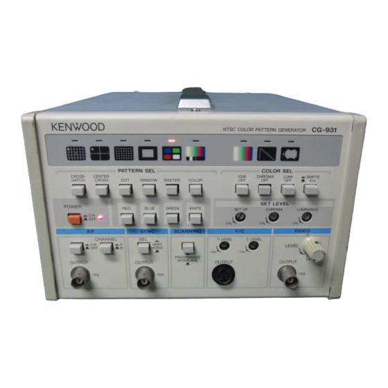
Page 8: Panel Explanation
4 . PANEL EXPLANATION FRONT P A N E L © Power Supply Supply Voltage AC 1 0 0 / 1 2 0 / 2 2 0 / 2 4 0 V, + / - 10% (max. 250 V ) / 5 0 / 6 0 Hz Power About 17 W... - Page 9 ® POWER (D Raster Select Switch The power ON/OFF push-switch-. When depressed, Switch for selecting the raster color. Moving from the LED lights up and the machine is in the operating left to right, this switch enables selection of red, state.
- Page 10 ® VIDEO LEVEL FRONT P A N E L Turn-knob for varying the video output level. This knob allows the video output level to be varied from 0 - 1.5 V p-p and, when turned all the way to the left (CAL), a signal of 1 V p-p can be obtained via the output terminal.
- Page 11 © S E T L E V E L ( C H R O M A ) © DOT When this semi-fixed turn-knob is turned clockwise, When this button is pushed, the screen displays a the chrominance level of the color signal can be 15x19, white-on-black dot pattern.
- Page 12 ® CHROMA OFF -.. - FRONT P A N E L When this button is pushed, the green lamp,on the upper portion lights up and the chrominance compo- nent is removed. If the button is pushed again, the screen returns to the previous state and the green lamp cuts off.
- Page 13 ® CHROMA • R E A R P A N E L The chrominance output of the S terminal on the front panel is output via the BNC terminal. ® REMOTE An Amphenol 24-pin connector utilized when the device is controlled remotely using the RT-62. This connector is installed only in models which are equipped for use with the RT-62.
-
Page 14: Precautions Use
P R E C A U T I O N S U S E D I R E C T I O N S F O R ODo not use the device in any place subjected to direct A C H I E V I N G O P E R A T I O N sunlight, as this may cause the internal temperature Plug the powercord into an AC socket AFTER you have to rise, resulting in unstable operation. - Page 15 PATTERN U S A G E OFF") Used when the Q, - I [ U , V ] and white signals 1) Cross-Hatch are not required for operations such as adjust- The center dot is used to adjust the static conver- ment of "...
- Page 16 COLOR BAR SIGNAL EIA COLOR BAR (BARS 1) SIGNAL < 7 5 % >- < 2 5 % BLA( WHITE SMPTE COLOR BAR (BARS 2) SIGNAL 6 7 % &y e> blu blk mg btk B L A C K 2 5 %...
- Page 17 R E M O T E O P E R A T I O N Control Signal RT-62 Pin RT-62 Pin Combinations of Combinations of (Remote Control Option Only) Number Number Pattern Signals Pattern Signals The pattern generator can be operated remotely using ®+©...
-
Page 18: Maintenance
7. MAINTENANCE .Caution: Read this page carefully to keep your safety. For Electric Shock Protection: Be sure to disconnect the power cable from the socket before conducting the following operation. P E P L A C I N G T H E F U S E In case the fuse has blown, locate the cause. -
Page 19: Adjustment
8. A D J U S T M E N T 2) Adjusting the sub-carrier frequency WARNING Connect a counter to the sub-carrier output on the THE FOLLOWING ADJUSTMENT INSTRUCTIONS rear panel and adjust C17 using the insulated ARE FOR USE BY QUALIFIED PERONNEL ONLY. TO adjustment rod. -
Page 20: Options
9. OPTIONS RT-62 Remote Controller 3) Adjusting the RF frequency OSet the PATTERN switch to "COLOR" and switch the A hand-held controller that allows remote operation of LUMI OFF and CHROMA OFF switches to "ON". the instrumentation. The controller contains two con- OSet the RF switch on the front panel to "ON"...