Table of Contents
- 1 Table of Contents
- 2 Limitation of Liability and Indemnity
- 3 Introduction of this Sterilizer
- 4 Warnings and Cautions
- 5 ( Parts Description and Functor)
- 6 Preparation for Use
- 7 Items to be Sterilized
- 8 Operating Instructions
- 9 Trouble Shooting Guide
- 10 In Case of Power Failure
- 11 ( Maintenance and Caret)
- 12 Specifications
INSTRUCTION MANUAL
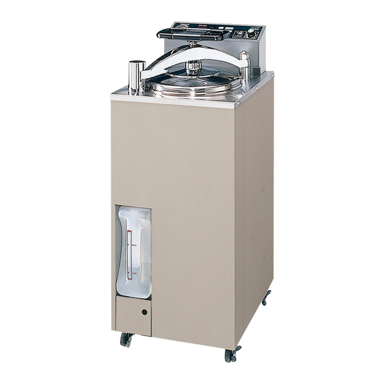
Labo Autoclave MLS-3020U
Thank you for purchasing a Sanyo Autoclave.
• Do not operate the unit until you have become familiar with this information.
• After reading this instruction manual, store it in a safe place for future reference.
MLS-2420U
CONTENTS
Page
1
2
3-8
9-14
15-16
17-18
19-25
26-27
27
28
29-30
Table of Contents

Related Manuals for Sanyo MLS-3020U


Summary of Contents for Sanyo MLS-3020U
-
Page 1: Table Of Contents
Labo Autoclave MLS-3020U MLS-2420U Thank you for purchasing a Sanyo Autoclave. • Do not operate the unit until you have become familiar with this information. • After reading this instruction manual, store it in a safe place for future reference. -
Page 2: Limitation Of Liability And Indemnity
SANYO and customer and to third parties and for property damage to the extent of the willful acts or the negligence of SANYO or the strict liability of SANYO caused by the acts or omissions of SANYO. Customer agrees defend, indemnify and... -
Page 3: Introduction Of This Sterilizer
INTRODUCTION OF THIS STERILIZER The unit must be operated as described in this manual, if procedure save not followed, equipment damage and personnel injury can occur. This manual contains important information on proper use and maintenance of this steri- lizer. All operators and supervisors are urged to carefully review and become familiar with the warnings, cautions and instructions contained herein. -
Page 4: Warnings And Cautions
WARNINGS AND CAUTIONS The following is a brief of safty precautions which must be observed when operating or servicing this sterilizer. WARNINGS indicate the possible dangerous accident to personnel and some hazards, and CAUTIONS indicate the possible damage to equipment. WARNING: 1 Always use the lifter when lifting the unit to prevent personnel injury or equipment damage. - Page 5 The unit should be plugged into a dedicated electrical line conforming to the following specifications. MLS-3020U : • 120Vunits : 120VAC(50/60Hz), 20A • 208Vunits I 208VAC(50/60Hz), 10Aor greater • 230Vunits : 230VAC(50/60Hz), 10Aor greater...
- Page 6 WARNINGS AND CAUTIONS 13 When you finished using the unit for the day, or if the unit will not be used for an extended period of time, be sure to turn off the unit's power switch(MAIN). Do not squeeze your finger or hand in the hinge of the door to reduce the risk of injury to persons.
- Page 7 WARNINGS AND CAUTIONS ,20 Do not load the flammable items or liquids such as Alcohol, Gasoline or any gasses, failure to take this precaution could result in explosion and malfunction of the sterilizer. Alcohol Use only vented closures do not use screw caps or rubber stoppers with crimped seals to reduce the risk of item's ex- plosions and malfunction of the sterilizer.
- Page 8 WARNINGS AND CAUTIONS ,27 Use only distilled water or tap water as the unit's water for evaporation. Never use chemicals such as alcohol, well wa- ter or salt water. They could cause the unit to explode or re- Well Water sult in corrosion.
- Page 9 WARNINGS AND CAUTIONS Open door slowly at the end of a liquid sterilization cycle. Do not allow hot bottles to be jolted. Failure to follow these pre- caution could result in bottle explosions! Do not move bot- tles, if any boiling or bubbling is present. ,35 Stand away from the sterilizer, when opening the door, the hot air and steam that escape can cause burns to hands, face and eyes.
-
Page 10: ( Parts Description And Functor)
PARTS DESCRIPTION AND FUNCTION Explanation of Action Label • Label,1 : This caution label explains burning hazard with touching the chamber, door or arm, if the unit is in operation or immediately afterward. • Label,2 : This caution label explains burning hazard with touching the chamber, door or arm, if the unit is in operation or immediately afterward. - Page 11 PARTS DESCRIPTION AND FUNCTION Label,4 (See P9) Label,3 (See P9) Label,2 (See P9) Label, 1 (See P9) Label,5 (See P9) Label,8 (See P9) Label,6 (See P9) Label,7 (See P9)
- Page 12 PARTS DESCRIPTION AND FUNCTION Wire-connector Main unit Magnet-holder and han- dle are connected by this connector. Chamber Items are placed in here to be sterilized. Magnet-holder Permanent magnet is equipped. Arm stopper It keeps the arm in the Magnet-plate correct position when the door is closed.
- Page 13 PARTS DESCRIPTION AND FUNCTION Gasket This gasket is fitted to the exhaust tank inlet opening, where the ex- haust hose is connected to the exhaust tank to keep airtight connection. Drain valve Exhaust hose This manual valve is Conveys steam and air used to drain sterilizing from the chamber to the water from the chamber.
- Page 14 PARTS DESCRIPTION AND FUNCTION (Control panel Pressure gauge Setting button (TEMP.TIM/UP.vDOWN) Power switch (MAIN) Indicates the pressure Used for setting and displaying the sterilization within the chamber. temperature and sterilization time, and for dis- playing the remaining sterilization time. (Refer to page 21 for detailed instructions.) PRESSURE GAUGE SAflYO...
- Page 15 PARTS DESCRIPTION AND FUNCTION Digital indicator lamp Time indicator lamp Heating process indicator lamp Displays the sterilization This lamp lights when the This lamp lights to display temperature in- temperature and steriliza- digital indicator lamp is formation and heating process of the tion time settings alter- displaying time informa- chamber.
-
Page 16: Preparation For Use
PREPARATION FOR USE Installation »Make sure to install the unit on a flat, sturdy surface floor. Lock all four casters. That the display indications will be difficult to read, if the unit is located under direct sunlight. •Avoid locations where the unit is exposed to air containing large amounts of moisture, salt or sulfur, as these could ad- versely affect the unit. - Page 17 PREPARATION FOR USE Electrical Connection • For 120 V units : MLS-3020U; The unit should be connected to an appropriate receptacle that is rated 20A or greater. MLS-2420U; The units should be connected to an appropriate receptacle that is rated 12.5A or greater.
-
Page 18: Items To Be Sterilized
ITEMS TO BE STERILIZED Precautions for sterilizing of liquids such as cultures and chemicals Mf large quantities of culture or other liquids are sterilized ,the de- lay of reaching time could be occurred between the chamber reaching time to setting temperature and the liquid in containers reaching time to setting temperature. - Page 19 ITEMS TO BE STERILIZED Sterilizing of items with using plastic containers >Only use heat resistance containers and do not overload the stainless baskets. Do not squeeze bottles against each other. Mf large quantities of culture or other liquids are sterilized with us- Made of ing plastic containers, set the sterilization time a little longer than plastic...
-
Page 20: Operating Instructions
OPERATING INSTRUCTIONS Starting Operation 1. Exhaust tank setup (1)Remove the exhaust tank from the main unit and, from the opening at the top, fill the tank with water up to the LOW level mark. (2) Insert the exhaust hose that is connected to the interior of the main unit into the opening at the top of the tank. - Page 21 OPERATING INSTRUCTIONS (—(Supplementary note)- Pour water for evaporation MLS-3020U units : 2 liters MLS-2420U units : 1.5 liters. Distilled water is ideal for using as water for evaporation. If distilled water is unavailable, tap water may be used. If these Never use well water, saltwater or hard water.
- Page 22 OPERATING INSTRUCTIONS 7. Close the door. # Turn the door gently clockwise with grasping the handle and until the arm comes to rest against the arm stopper. a s n e s # Even if the [ifcmmjyjfl f' > continue to turn the handle until it becomes tight.
- Page 23 OPERATING INSTRUCTIONS ^ - ( Supplementary note )- For120V, 280Vunits : Lowering the sterilization temperature setting by 2°C(3.6°F)or more after the chamber has been heated causes the temperature indication to flash on and off. For 230V units : Lowering the sterilization temperature setting by 4°C(7.2°F) or more after the chamber has been heated causes the temperature indication to flash on and off.
- Page 24 OPERATING INSTRUCTIONS 9. Start sterilization. # Press the H H s f l button. A short beep sounds and "°C"lamp lights to indicate that sterilization is in process. (RESET) START J^ Short beep The digital indicator begins to register, when the temper- ature inside the chamber reaches 80°C.
- Page 25 OPERATING INSTRUCTIONS 11. Finishing of sterilization # l f the sterilization finishes, the buzzer will sound a beep and the Heating Process Indicator lamp will flushes to indicate that sterilization is finished. The digital indicator lamp will display the temperature of °c 1—;...
- Page 26 OPERATING INSTRUCTIONS 13. Completion ive long beeps sound in succession and the indica- tor of completion on the digital indicator lamp lights I MIN I to show that it is safe to open the door and to re- ("Completion" indicator) move the contents of the unit.
-
Page 27: Trouble Shooting Guide
TROUBLE SHOOTING GUIDE Check the following points if the unit seems to be malfunctioning. Pape of Problem Cause Remedy Reference •Power won't turn on. • I s the power supply cord con- •Connect the power supply nected? cord. • I s the circuit breaker that con- •... -
Page 28: In Case Of Power Failure
TROUBLE SHOOTING GUIDE If an error indication appears If an error indication appears and the buzzer beeps intermittently while the unit is operating,the unit's safety device could be triggered, halting operation. And consult the table below for points to check and corrective actions. To cancel the error indication: Switch off the power to turn off the error indications and buzzer sound. -
Page 29: ( Maintenance And Caret)
Be careful not to rub too forcefully to avoid damaging the sensor sensor (MLS-3020U) element of the heat sensor mounted on the heater. Drain off the water used to rinse the chamber through the drain opening. -
Page 30: Specifications
SPECIFICATIONS Model Designation MLS-3020U 120Vunits : 120VAC(50/60Hz) Power supply (Dedicated 20A circuit required) CSA Approved. 208Vunits : 208VAC(50/60Hz ),9.6A CSA Approved. 230Vunits : 230VAC(50/60Hz ),8.7A CE Marked Powei* consumption 440 X 550 X 1050mm External dimensions 17-8/25" X 21-13/20" X 41-17/50"... - Page 31 SPECIFICATIONS Model Designation MLS-2420U 120Vunits : 120VAC(50/60Hz ),12.5A Power supply (Dedicated 20A circuit required) 208Vunits : 208VAC(50/60Hz ),7.2A 230Vunits : 230VAC(50/60Hz ),6.5A CE Marked Power consumption 1.5kW 380 X 490 X 840mm External dimensions 14-15/16" X 19-1/5" X 33-3/8" Mass(Approx.) 47kg(103.6lbs) 240 X 450mm Chamber dimensions(dia.x depth)
- Page 32 SANYO Electric Co., Ltd. 3RJ6P10101602 Printed in Japan...