Table of Contents
Table of Contents

Related Manuals for Honeywell MPA1


Summary of Contents for Honeywell MPA1
- Page 1 Access Control Unit MPA1 User Guide Document -800-26311_Rev-B – July 2020...
- Page 2 Revisions Date Revisions 02/2020 Document created. 07/2020 Document updated with ULC Features...
-
Page 3: Table Of Contents
Navigating through MPA ................10 The MPA1 Dashboard Accessing the Menu 2 Basic Settings . - Page 4 6 MPA1 Accounts ........
- Page 5 All product and brand names are the service marks, trademarks, registered trademarks, or registered service marks of their respective owners. Printed in the United States of America. Honeywell reserves the right to change any information in this document at any time without prior notice.
-
Page 6: Getting Started
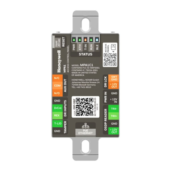
Getting Started Overview The MPA1 is a modular 1 Door access control system. An MPA1 access control site is configured with a host system and access control units that exceed existing NetAXS-123 specifications and approvals. These units also communicate with each other. Each access control unit, or panel, has one reader port, which can support up to two OSDP readers. -
Page 7: Setting Up An Ethernet Port
1) The panel that you are connecting to the computer is the Primary panel. The panel is set as Primary panel using the Device Utility App. 2) When creating a user in MPA1 -> Web server, the administrator should obtain and maintain the consent. - Page 8 Configure the computer’s network connection: Select Start > Settings > Control Panel. Click Network and Dial-up Connections. Identify your local Ethernet connection (commonly labeled Local Area Connection), and right-click the icon to display the Local Area Connection Properties screen. Highlight the Internet Protocol (TCP/IP) connection. Click Properties to display your system’s current Internet Protocol properties.
- Page 9 When connecting to the web using a browser, you must use https:// for a secure connection. The standard http:// that is the default in most browsers will not work. Press the Enter key to display the Honeywell MPA1 login screen. www.honeywell.com/security...
- Page 10 On initial signing in, you will be asked to change your password to a new password. For more information see Creating MPA1 Accounts on page 115. Click Sign In. By default, the MPA1 opens to the Dashboard. Document 800-26311_ A - April 2020...
-
Page 11: Navigating Through Mpa
10 | MPA1 User Guide Navigating through MPA The MPA1 Dashboard On the MPA1 Dashboard, you can see the following: • A list of all the panels in the loop. • Any offline panels. • The number of currently existing entries in the database. -
Page 12: Accessing The Menu
| 11 Accessing the Menu In the upper left corner is the Menu button, allows you access to all of the MPA functions. Figure 1-1 Main Menu Document 800-26311_ A - April 2020... - Page 13 (such as Inputs, Configuring Panel I/O and Groups Outputs, and Output on page 52 Groups) Specify that an account Creating MPA1 Accounts on page is Administrator, Service, or Operator. Select Lan- guage Preference. Sign out The current user www.honeywell.com/security...
- Page 14 | 13 This page is intentionally left blank Document 800-26311_ A - April 2020...
-
Page 15: Basic Settings
| 17 Basic Settings Overview This chapter explains the MPA1 configuration functions as accessed via the web server. These functions should be performed only by the system administrator or service personnel. CAUTION: The sequence of MPA1 configuration tasks is critical. If you do not follow the sequence described in... -
Page 16: Configuring The Evl (Ethernet Virtual Group)
Configuring the EVL (Ethernet Virtual Group) What is an EVL? An Ethernet Virtual Loop (EVL) allows a group of IP network connected MPA1 controllers to be managed as a group, through an embedded Web Server residing on one of the controllers. -
Page 17: Setting For Evl Mode
Setting for EVL mode There are no DIP Switches on an MPA1. When an MPA1 panel is used in EVL mode. The panel needs to be set up with the device Utility App. The panel is identified by its MAC address. - Page 18 20 | MPA1 User Guide Figure 2-2 Selecting Host/Loop Communication Tab Set up Communication attributes (see Figure 2-2): Select Web as Host Connection Type. Ethernet Virtual Loop is the only available option. Click Save. Setting Up an Ethernet Port on page...
- Page 19 | 21 Figure 2-3 Network Configuration for EVL Log into the Primary controller from a browser. Setting Up an Ethernet Port on page Register Secondary EVL controllers (see Figure 2-4): Note Only secondary panels can be Registered and Unregistered. Navigate to the EVL tab: Menu > Panel Configuration > Advanced > EVL Discovery.
- Page 20 22 | MPA1 User Guide Click REGISTER to register a panel. The REGISTER buttons changes to UNREGISTER when the registration is successful. Figure 2-5 Registered Secondary Controllers You have now finished creating an Ethernet Virtual Loop. www.honeywell.com/security...
-
Page 21: Managing Configuration Data
| 23 Managing Configuration Data Configuration data is managed on a system of panels interconnected in a loop. Configuration data is either common (shared and stored on all online panels when the data is entered) or panel specific (unique to each panel). Common data includes: •... -
Page 22: Configuring Host/Loop Communications
24 | MPA1 User Guide Configuring Host/Loop Communications To maintain your MPA1 system configuration or to monitor its status, you must connect to the panel using one of three modes: • Host mode (monitor only) – a host software system, such as WIN-PAK™ or MAXPRO Cloud, connects to the panel (through the primary panel, which has an on-board PCI communications adapter). - Page 23 Whenever this box is checked and the page is saved, the new key must be entered in WIN-PAK. Disable Encryption Select to disable encrypted communication between MPA1 Primary and WIN-PAK Host. Disabling encryption creates an insecure system and is not recommended.
- Page 24 26 | MPA1 User Guide Figure 2-7 Selecting WEB on the Host/Loop Communications Tab Configure the host settings. Table 2-3 Web Host Communication Mode Settings Host Setting Description Mode EVL - If Primary provides access to Ethernet Virtual Loop. Time Sync Synchronizes the primary’s time with the secondary...
-
Page 25: Initial Panel Setup
| 27 Figure 2-8 Selecting MAXPRO Cloud on the Host/Loop Communications Tab Enter the Server URL. Click Save. Initial Panel Setup You can access Panel configuration in two ways: • Click Panels in the Dashboard to access the Panels interface, or Figure 2-9 Navigating to the Panels Interface •... -
Page 26: Entering A Panel Name
28 | MPA1 User Guide Figure 2-10 Panels Interface Entering a Panel Name Note Panels can be configured only if the Host Communications is set to Web. Navigate to the Settings panel: Dashboard > Panels > Settings, or • •... -
Page 27: Configuring The Network Settings
| 29 Figure 2-11 Settings Panel Click the Panel Name field, and then enter a panel name. Click Save. Configuring the Network Settings In the Panel Configuration page, you can configure the following network-related settings: • View the panels MAC Address •... -
Page 28: Configuring Time Management
30 | MPA1 User Guide The General section allows the user to: • Configure the panel's name • View the active firmware version • Reset the panel • View the panel type • View the last boot time of the panel Other fields in the Panel Configuration >... - Page 29 Enable/Disable Time Sync. Enabling Time Sync Communications synchronizes the secondary panels with the main panel. Time (in mins) Enter a value for how often the MPA1 panels checks and synchronizes the panel times. Enter between 60 and 32,767 minutes. www.honeywell.com/security...
- Page 30 | 33 Configuring Behavior Settings In the Behavior Settings section of Panel Configuration, you can enable/disable the following: • Anti-Passback–When enabled, a valid card is required for entry and exit. The card holder must use the card in the proper IN/OUT sequence—that is, a card presented at an IN reader must then be presented at an OUT reader, or vice versa—a card presented at an OUT reader must then be presented at an IN reader.
- Page 31 (3-59) or hours (1-12). Configuring Schedules The MPA1 panel controls access by using schedules, or time schedules. Inputs, outputs, groups, readers, access groups, and cards through access groups are all configured with schedules by which they will be energized or de-energized, enabled or disabled.
- Page 32 | 35 Figure 2-13 Time Management - Schedules Creating a schedule Click in the Schedules interface to add a new schedule. Enter a schedule name. Click and drag to define the parameters of the schedule, including days of the week and hours.
- Page 33 36 | MPA1 User Guide Configuring Holidays Holidays are special days of a week. They are similar, but override standard weekdays. If a day programmed as a Holiday occurs in the panel, the panel treats that day as the Holiday type, regardless of the actual day of the week (Monday-Sunday).
- Page 34 | 37 Note Each Holiday added is considered a full day, extending from midnight to midnight. Modifying a Holiday Click to select the holiday in the Holidays list. Figure 2-15 Modifying a Holiday Modify the holiday. Click Save. A message appears to confirm that the charges were saved. Deleting a Holiday Click to select the holiday.
-
Page 35: Configuring Spaces
38 | MPA1 User Guide Figure 2-16 Deleting a Holiday A delete icon appears Click the delete icon. A Delete Confirmation message appears. Click OK. A Successfully Deleted message appears to indicate the deletion was successful. Configuring Spaces Configuring Spaces Before you can configure doors, you must assign doors to a space. - Page 36 | 39 Figure 2-17 Navigating to the Spaces Interface • Or click Configuration in the Menu. Click to create a new space. Figure 2-18 Creating a New Space The ASSIGN DOORS TO SPACE window opens. Note If all of your doors are already assigned to space, then you receive a message explaining that You don’t have any doors available.
- Page 37 40 | MPA1 User Guide Figure 2-19 ASSIGN DOORS TO A SPACE window Enter a space name in the Name your Space field. Click in the AVAILABLE DOORS pane to select the door. The door appears in the ADDED DOORS pane.
- Page 38 | 41 Figure 2-20 Access Groups Interface Click to select an Access Group, then click EDIT. Figure 2-21 Selecting an Access Group Click + under Entity to expand a space and reveal the doors that belong to that space. Click to select a door, then select No schedule assigned from the Schedules drop-down menu.
-
Page 39: Configuring Doors
42 | MPA1 User Guide Figure 2-22 Selecting a Door Click Save. Configuring Doors Each panel supports from 1- door. For each door, you must configure the readers, inputs, and outputs. Note You must assign doors to a Space before you can configure the doors. See... - Page 40 | 43 Figure 2-23 Configure your Spaces Tab Click Configure your Spaces to expand the configured spaces, then click a Space to open it, then click on a door in that space to select it. Figure 2-24 Door Configurations Configuring Door Reader Settings The Reader settings tab allows you to configure the following settings for both Readers A(IN) and B(OUT) for each door: •...
- Page 41 44 | MPA1 User Guide Figure 2-25 Door Configurations Enter a Door Name. Select a schedule for the following settings: • Disable Reader • Lockdown Reader • Card and PIN • Card or PIN • PIN only • Card Only Note The order of the above list is the priority order.
- Page 42 | 45 About Supervisor Mode Supervisor mode enables a supervisor to enter without allowing general access. When this mode is enabled, the reader LED changes color four times per second (usually red then green). Table 2-5 Supervisor Mode LED Color Cycle Action LED Cycle Reaction...
- Page 43 46 | MPA1 User Guide Note You must enable Anti-Passback in Panel Configuration before you can enable it here. See the Behaviour Settings section in Figure 2-10 page Anti-Passback: When enabled, a valid card is required for entry and exit. The card holder must use the card in the proper IN/OUT sequence—that is, a card presented at...
- Page 44 | 47 Note The duress output feature requires the following configurations: • Duress must be enabled on the Panel Configuration > Settings > Behaviour Settings tab. See Figure 2-10 page • A schedule/schedule must be selected for Card and PIN in the Doors configuration.
- Page 45 48 | MPA1 User Guide Four inputs are associated with each of the doors on a MPA1 panel: • Status – Provides door status information (DrCnt). Egress – Allows the door to open or close normally without generating an alarm (REX).
- Page 46 | 49 Select Input Modes. Configuration Description Normally Closed means that the input’s normal state is closed. (Default setting). Open means that the input’s normal state is open. State Unsupervised means that the input’s electrical circuit is wired in one path without alternative paths supervised by resistors. (Default setting) Supervised means that the input’s electrical circuit is wired in one path with alternative paths supervised by resistors.
-
Page 47: Configuring Door Outputs
Lock operation definition Scheduling Two outputs are associated with the door on a MPA1 panel Lock- Controls the lock in an electronic state to open or close the door (Default SWITCHED GND) Reader LED-Controls the LED of the Reader(s) in Green state (via OSDP command) - Page 48 (default) Fail Secure mode output in normal state is not active. A lock that needs to be powered to unlock a door will use the Fail Secure mode. If the MPA1 is not powered the output and lock remains in it normal state.
-
Page 49: Configuring Panel I/O And Groups
52 | MPA1 User Guide Click Save. Configuring Panel I/O and Groups To view a configuration of a group of outputs, click Group and select the group number from the drop-down list. The group configuration screen appears. Note that you can only view the group configuration from this screen. - Page 50 | 53 Figure 2-29 Configuring Panel Inputs Click to select an input. Select Input Modes. Configuration Description Normally Closed means that the input’s normal state is closed. (Default setting). Open means that the input’s normal state is open. State Unsupervised means that the input’s electrical circuit is wired in one path without alternative paths supervised by resistors.
- Page 51 54 | MPA1 User Guide Configure Shunt and Debounce times. Configuration Description Shunt Time Specifies the amount of time for which the inputs are shunted, or (h:m:s) de-activated. The maximum length of time is 1 hour, 45 minutes, 59 seconds.
- Page 52 (default) Fail Secure mode output in normal state is not active. A lock that needs to be powered to unlock a door will use the Fail Secure mode. If the MPA1 is not powered the output and lock remains in it normal state. In Fail Safe mode the output in the normal state is activated.
- Page 53 56 | MPA1 User Guide Setting Description Energized Specifies the period during which the output relay is automatically energized. Select a schedule (that you created in Entering a Panel Name on page 28) from the drop-down list. Disable Interlocks Specifies the period during which the interlocks that control the output will be disabled.
-
Page 54: Configuring Card Formats
| 57 Figure 2-31 Configuring Output Groups Click to add a new group. Configure the following for each output group: Setting Description Name Enter a unique name for the group Pulse Time Configure how long a device assumes abnormal status, such as a horn sounding or a released door strike. - Page 55 58 | MPA1 User Guide Navigate to Card Formats: • Dashboard > Panels > Card Formats • Menu > Panel Configuration > Card Formats Table 2-7 Card Format Settings Settings Description Available Formats Lists all the formats in the panel. All formats, new ones as well as the eight default formats, are listed under Available Formats.
- Page 56 Selected Formats setting in Table 2-7. Click Save. If you want to create a new card format, click Circled Add icon to display an empty Card Format data layout screen. MPA1 Document 800-26311_ A - April 2020...
- Page 57 60 | MPA1 User Guide Use the field descriptions in Table 2-8 to define the layout and click Save. Table 2-8 Panel Configuration > Card Formats Settings Description Card Format Name Displays the name by which the format will be listed in the Card Formats tab.
-
Page 58: Managing Site Codes
| 61 Table 2-8 Panel Configuration > Card Formats (continued) Settings Description Odd Parity Lists where on the card that odd parity is being observed. Start - First bit in the card where odd parity begins. Num - Number of bits to the right of the start bit, including the start bit, to include in the odd parity check. - Page 59 62 | MPA1 User Guide The Site Codes panel enables you to: • Create one or more site codes. • View existing site codes. • Modify an existing site code. • Delete a selected site code. Navigate to the Settings panel: •...
-
Page 60: Configuring Interlocks
| 63 The Name and Code fields become active. Make your modifications, then click the green check mark to save. A message appears confirming that the new site has been Successfully Updated. Deleting a Site Code Click to delete a site code. Configuring Interlocks An interlock is a programmed connection between two points. - Page 61 64 | MPA1 User Guide Creating Interlocks Click to open the Create Interlock window. Figure 2-34 Create Interlocks Interface Enter a name for the new Interlock. Select configurations for the Triggers (Input, Output, or Group), Reaction (Input, Output, or Group), Alarm Action, and Normalcy (the state to which the trigger returns).
- Page 62 | 65 Configuration Description Interlock Then Execute (Alarm Action) – Specifies the reacting Actions component’s action when the trigger’s change of state occurs. Select the action from the available options. Upon Resuming (Normalcy) – Specifies the reacting component’s action when the trigger returns to the normal state. Select the action from the available options.
-
Page 63: Configuring People And Cards
66 | MPA1 User Guide Deleting Interlocks Click to select an Interlock. Figure 2-35 Deleting an Interlock Click the Delete button . A message appears asking for confirmation. Click OK. Enabling/Disabling Interlocks Click the Enable/Disable button • . A confirmation appears if successful. - Page 64 | 67 Figure 2-36 People & Cards Configuration Interface Creating a Person on the People tab to create a new user. Click to Figure 2-37 Creating a New Person Enter a first and last name. Enter a card Number. Or click Add near the bottom of the window to assign a card from an available set of cards.
- Page 65 68 | MPA1 User Guide Optional: Enter a note, such as Department number, phone extension, or a birthday, for example. Notes can be up to 20 characters. Turn Trace on or off. Trace provides a record of the card holder’s path through the facility by sending an alarm message to the alarm monitor whenever a card with trace enabled is presented at a reader.
-
Page 66: Configuring Cards
| 69 Figure 2-39 Deleting a Person Click the delete icon . A confirmation message appears. Click OK to confirm the deletion. Configuring Cards A card is encoded with a unique number and the person’s access group grants rights to access system resources. - Page 67 70 | MPA1 User Guide Figure 2-40 Cards Configuration Interface Adding a New Card Click in the Cards tab of the People & Cards window to open the configuration options. Figure 2-41 Adding New Cards Enter either a card number (if adding a single card) or a range (if adding multiple cards).
- Page 68 | 71 Note A PIN is optional; however, if the door reader is configured to require PIN identification (see Configuring Door Reader Settings on page 43), then you must create a PIN for the card holder here. The PIN has a maximum of six digits.
- Page 69 72 | MPA1 User Guide Figure 2-42 Modifying a Card Make the changes to the card, then click Save. Deleting Cards Click the box next to the card. A delete icon appears Figure 2-43 Deleting a Card Click the delete icon .
-
Page 70: Configuring Access Groups
| 73 Configuring Access Groups Every card is assigned an access group, which specifies the schedule, or time schedule, during which the card holder can be granted access at a specific door. For example, an access group embedded in an employee’s card might allow the employee to enter the facility only through door 2 from 6:00 AM to 6:00 PM, Monday through Friday. -
Page 71: Creating A New Access Group
74 | MPA1 User Guide Creating a New Access Group Click to open the new access group configuration panel. Figure 2-45 Access Group Configuration Page Enter a name in the Access Group name field. Click to select People for this access group. - Page 72 | 75 This page is intentionally left blank Document 800-26311_ A - April 2020...
-
Page 73: Monitoring And Reporting
MPA1 has been evaluated for standalone use only. Monitoring features are supplementary only and have not been evaluated by UL. Monitoring Monitoring Alarms and Events Note MPA1 is listed for access control only. No burglary applications have been investigated. Document 800-26311_ A - February 2020... - Page 74 78 | MPA1 User Guide Alarms Alarms are system-generated messages that might indicate the need for user attention. To view alarms and events, you have to navigate to the Alarms & Events window. Events Events are both panel- and web-generated events. Panel events include the recording of a card read by a reader.
- Page 75 | 79 Table 3-1 Alarms & Events Fields Field Description Space Displays the name of the space where the alarm occurred. Filter by Space: You can filter alarms and events by the space by clicking the filter icon next to Space in the header.
-
Page 76: Monitoring/Managing Doors
80 | MPA1 User Guide Table 3-1 Alarms & Events Fields Field Description Card Holder Name Reports a Card Holder name on events where the Card Number is an actual card in the system. Filter by Card Holder Name: You can filter alarms and... -
Page 77: Monitoring Inputs
| 81 Figure 3-2 Device Management Window Monitoring Inputs The panel supports door, panel, and auxiliary inputs. The door inputs provide egress, status, and tamper monitoring. The auxiliary inputs support any monitoring devices connected. The Input Status screen enables you to: •... -
Page 78: Monitoring Outputs
82 | MPA1 User Guide Restoring the Schedule Click Restore to Schedule to restore the input to its shunt state based on its current schedule. A window appears to confirm the action. Click OK. Monitoring Outputs An output is a device that changes state when it is energized, pulsed, or time-zone controlled. -
Page 79: Monitoring Output Group
| 83 Figure 3-4 Device Management Window - Auxiliary Connections - Outputs Note The Output Status screen dynamically refreshes when the output status changes. Table 3-2 Output Management Settings Field Description Energized Click to energize an output for an indefinite period of time. De-energized Click to de-energize an output for an indefinite period of time Pulse... - Page 80 84 | MPA1 User Guide Figure 3-5 Device Management - Auxiliary Connections - Output Groups Table 3-3 Output Groups Management Settings Field Description Energized Click to energize an output for an indefinite period of time. De-energized Click to de-energize an output for an indefinite period of time Pulse Click to pulse an output for the configured period of time.
- Page 81 | 85 Click Outputs on the Doors configuration window to open the Outputs configuration pane. Figure 3-6 Door Outputs Configuration Interface Enter an Output Name. Configure the following general settings. Configuration Description Pulse Specifies the duration for which the device will assume abnormal status.
-
Page 82: Reporting
86 | MPA1 User Guide Configuration Description Interlocks Enables you to disable the interlock, or programmed interaction between two points. When enabled, this point ignores all interlock actions to it, effectively disabling it from being a Reacting Component. TZ Card Toggle... -
Page 83: Generating Diagnostic Reports
| 87 Figure 3-7 Alarms & Events Window When you click on one of the download events buttons, a dialog box pops up to advise that the file you are downloading is not secure, and that you save that file in a secure location. -
Page 84: Generating People/Card Reports
It then asks for you to confirm that you want to upload the report. Click OK to confirm. A. Bin file is generated which can be saved and sent to Honeywell technical support for diagnosis. Click to save the file in a secure location of your choice. -
Page 85: Maintenance
| 89 Maintenance Overview This chapter contains: • System-wide backup • Panel Resets and Restorations • Firmware Upgrades • Primary / Secondary Panel Replacement Use Case Scenarios • Primary / Secondary Panel Hard Default Use Case Scenarios Backing Up Navigate to the File Management interface: Select a panel from the Panel Configuration interface. -
Page 86: Upload (From Panel)
Diagnostic Report Troubleshooting information can be retrieved from the panel using this function. The report is not readable to the customer and is useful only as a tool to help Honeywell technical support troubleshoot certain unusual problems. To generate a diagnostic report, Select “Diagnostic Report”... - Page 87 | 91 Note The Diagnostic Reports saves as a bin file. System-wide Backup Uploads Card, Common and Panel configuration data in a proprietary internal format. Common data includes: • Schedules • Cards • Card Formats • Holidays • Access Group Name (access group details are panel-specific) •...
- Page 88 92 | MPA1 User Guide Taking System-wide Backup for panel(s) is only allowed from Primary (gateway) panel's file management page. • Upon selecting system wide backup, UI will show a field to enter password • Password Must follow rules for valid password checks - need not be same as current user/admin password: •...
- Page 89 | 93 Downloading a Card Database Report (.CVS file) from the Host System to the Panel Click Browse to locate the .CSV file. This .CSV file is usually the Card Report that was previously uploaded from the panel as a backup. Click Download to download the file.
- Page 90 94 | MPA1 User Guide Note Restoring any panel whose back-up info is not available in the .bkp file will not be restored. Note During the restore process, the system will prompt for a password that must match the password that was used when the backup file was created.
-
Page 91: Synchronizing A New Panel With Information On An Existing Panel
Replace a Primary Panel in an Existing Loop (Web Mode) Overview Details the steps to replace a MPA1 "Primary" panel with existing "Secondary" panels which is connected to the Ethernet Virtual Loop (EVL). The System Wide Restore in the Primary is required with an existing backup. -
Page 92: Replace A Secondary Panel (Web Mode)
MPA1 User Guide Replace a Secondary Panel (Web Mode) Overview Details the steps to replace a MPA1 "Secondary" panel in an existing loop of Ethernet Virtual Loop (EVL) in Web Mode. Secondary Panel Replacement and Synchronization Step # 1. Un-register the original Secondary panel in the Primary panel. Navigate to: •... -
Page 93: Hard Default An Existing Secondary Panel (Web Mode)
Hard Default an Existing Secondary Panel (Web Mode) Overview This section details the synchronization process of a MPA1 "Primary | Secondary" panel after hard defaulting an existing "Secondary" Panel in a loop of Ethernet Virtual Loop (EVL) in Web Mode. -
Page 94: Synchronization Detail Chart
98 | MPA1 User Guide Synchronization Detail Chart Synchronization Primary panel to the Secondary panel synchronization occurs at the time the Secondary panels are "Registered" with the Primary. The Synchronization only occurs at the time of panel registration and will include Common Data. -
Page 95: Restore Entire Loop Detail Chart
| 99 Restore Entire Loop Detail Chart System Wide Backup Restore: Primary panel to the Secondary panel downloads the following: • Common Data • Panel-specific data Example: System Restore in the following order with (3) Secondary Panels: The 1st Secondary panel will receive the backup and reboot. The 2nd Secondary panel will receive the backup and reboot The 3rd Secondary panel will receive the backup and reboot. -
Page 96: Restoring The Panel To Factory Default Settings
100 | MPA1 User Guide If the Secondary panel comes back on line the panel will not be serviced at the time of the restore. The "Panel Only" restore will only restore "Panel-specific data" to the particular panel. Restoring the Panel to Factory Default Settings Press the Reset button continuously for 30seconds. -
Page 97: Firmware Upgrades
Click Reset. Click OK to reboot the panel. Firmware Upgrades Panel Requirements MPA1 panels must first be upgraded to latest firmware. See the release notes for more information. Note The secondary (downstream) EVL panels should be upgraded first, and then the primary (MASTER). -
Page 98: Planning For The Firmware Upgrade
Remember to return their configuration back to a downstream panel once the upgrade has been successfully completed. The firmware and Operating System (OS) can be downloaded from the Honeywell Download Center at the following site: https://mywebtech.honeywell.com/. Updating the MPA1 Panel Using the Web Interface Step 1: Installing the new File Navigate to the web server Panel Configuration >... - Page 99 After upgrading a MPA1 panel, you must clear your browser’s cache. See Clearing the Cache and Cookies in the Internet Browsers Used by the MPA1 Web Server for details. Document 800-26311_ A - February 2020...
- Page 100 104 | MPA1 User Guide This page is intentionally left blank www.honeywell.com/security...
-
Page 101: Caches And Certificates
Caches Clearing the Cache and Cookies in the Internet Browsers Used by the MPA1 Web Server The MPA1 supports Google Chrome. It is recommended that the cache be cleared following a successful upgrade. Note After upgrading a MPA1 panel, you must clear your browser’s cache. -
Page 102: Generating And Installing Certificates
106 | MPA1 User Guide Select Settings to display the settings screen. • Click the Advanced link at the bottom of the Settings screen to display the Clear Browsing Data screen: • Ensure that the selections pictured in the above image are chosen. - Page 103 | 107 Go to Advanced Menu > Security Certificate tab. Create Request will be selected at the top of the pane. Fill in the fields as shown above. Make sure that the panel IP address is in the common name field. Select Create TLS Certificate Signing Request.
- Page 104 108 | MPA1 User Guide You will then note that there is text in the Certificate Signing Request field. Copy all of the text out of this field and send it to the signing authority of your choice. You will receive a signed certificate (also in text format).
-
Page 105: Section 2 - Installing The Master Certificate Into The Browser
| 109 Navigate to the Update Certificate pane and paste the certificate into the designated field. Select Save Certificate. When the save is complete you will notice that the text at the bottom of the page reports "Currently using: User Certificate." Section 2 - Installing the master certificate into the browser When using a self-signed certificate it is necessary to install the matching master certificate into all computer’s browsers that access the MPA panels. - Page 106 110 | MPA1 User Guide After you have installed the certificate file onto the panel but before you install the master certificate, the browser will still display the broken lock. Open Internet Explorer and select Tools (gear icon) > Internet options.
- Page 107 | 111 Select the Trusted Root Certificate Authorities tab, then select Import: The Certificate Import Wizard will appear. Document 800-26311_ A - February 2020...
- Page 108 112 | MPA1 User Guide Select Next and Browse. Change the file type to All Files. Then select the master signed certificate from its location on your machine. www.honeywell.com/security...
- Page 109 | 113 Click Open to load the file. Confirm Yes when this warning comes up: Success! Document 800-26311_ A - February 2020...
- Page 110 114 | MPA1 User Guide Now if you scroll down the list of Trusted Root Certificate Authorities you should see the signed certificate in the list: Close any Chrome windows that were open. Navigate to the URL MPA Address and the login screen will appear.
-
Page 111: Mpa1 Accounts
| 115 MPA1 Accounts Creating MPA1 Accounts A User is someone who will be using the MPA1 software in one or more functional roles. The Manage Accounts configuration window allows you to configure the following: • Add, modify, delete user accounts •... - Page 112 116 | MPA1 User Guide Note User name is free from text field, if personal identifications details are used for the User name, then it is the responsibility of system administrator to make sure appropriate consent is obtained from the user and maintained to meet GDPR compliance.
-
Page 113: Modifying A User Account
| 117 Figure 6-2 Accounts Configuration Interface Click to create a new account. Enter a name. 10. Enter a Password. 11. Select an Account Type, either Administrator, Service, or Operator. See Table 6-1 page 115 for more about these accounts. 12. -
Page 114: Deleting A User Account
118 | MPA1 User Guide Figure 6-3 Modifying a User Account Make the changes, and then click Save. Deleting a User Account Click to select an account in the Manage Accounts interface. A delete icon appears. Click , then click OK to confirm the deletion. -
Page 115: Technical Support
+31108080688 Technical Support, Option 2 (Access Control) Hours of Operation | Monday through Friday, 9:00 am - 7:00 pm EST Following are the tech support E-mail IDs of different countries. EMEA ITALY [email protected] [email protected] SPAIN [email protected] FRANCE [email protected] THE NETHERLANDS [email protected]... - Page 116 120 | MPA1 User Guide Web Support Technical Assistance: https://honeywellaccess.com MyWebTech Customer https://mywebtech.honeywell.com Support Schedule Support: https://honeywellsystems.com/ss/ schedulesupport/index.html Online Training: https://honeywelldiscovertraining. www.honeywell.com/security...
-
Page 117: Appendix
| 121 Appendix This product is compliant with ULC 60839 -11-1 Grade 1. Below tables lists the evaluated mandatory requirements. Optional ULC 60839-11-1 requirements has not been evaluated by UL. Note Table 7-1 Access Point Interface requirements Yes/No Grade 1 OP/M When the release time is system-defined, the permitted value shall not be less than 3 s Provide access control for entry into a protected (controlled) area... - Page 118 122 | MPA1 User Guide Table 7-4 Overriding requirements Yes/No Grade 1 OP/M The electronic access control system shall not prohibit the free exit granted by other emergency systems (e.g. fire, environmental) Table 7-5 System self-protection requirements Yes/No Grade 1 OP/M...
- Page 119 | 125 Document -800-26311_Rev-B – July 2020...
- Page 120 © 2020 Honeywell International Inc. All rights reserved. No part of this publication may be reproduced by any means without written permission from Honeywell. The information in this publication is believed to be accurate in all respects. However, Honeywell cannot assume responsibility for any consequences resulting from the use thereof.