
Related Manuals for Sony HMI-3000MT


Summary of Contents for Sony HMI-3000MT
- Page 1 4-468-269-15 (1) 2017-10 Head Mounted Image Processor Unit Instructions for Use Before operating the unit, please read this manual thoroughly and retain it for future reference. HMI-3000MT © 2013 Sony Corporation...
- Page 2 Indications for Use/Intended Use This symbol indicates the date of manufacture. The Sony HMS-3000MT is intended to provide 3D and 2D color video displays of images from surgical endoscopic/ This symbol indicates the serial number. laparoscopic camera systems and other compatible medical imaging systems.
- Page 3 If you have any questions about this product, you may call; – Connect the unit and the affected devices to different Sony Customer Information Service Center branch circuits. 1-800-222-7669 or http://www.sony.com/ For more information, consult qualified Sony service personnel. (Applicable standard: IEC 60601-1-2) Declaration of Conformity Trade Name...
- Page 4 Important EMC notices for use in medical environments • The HMI-3000MT needs special precautions regarding EMC and needs to be installed and put into service according to the EMC information provided in the instructions for use. • Portable and mobile RF communications equipment, such as cellular phones, can affect the HMI-3000MT.
- Page 5 Guidance and manufacturer’s declaration – electromagnetic immunity The HMI-3000MT is intended for use in the electromagnetic environment specified below. The customer or the user of the HMI-3000MT should assure that it is used in such an environment. IEC 60601 Compliance Immunity test Electromagnetic environment –...
- Page 6 Guidance and manufacturer’s declaration – electromagnetic immunity The HMI-3000MT is intended for use in the electromagnetic environment specified below. The customer or the user of the HMI-3000MT should assure that it is used in such an environment. IEC 60601 Compliance Immunity test Electromagnetic environment –...
- Page 7 Recommended separation distances between portable and mobile RF communications equipment and the HMI-3000MT The HMI-3000MT is intended for use in an electromagnetic environment in which radiated RF disturbances are controlled. The customer or the user of the HMI-3000MT can help prevent electromagnetic interference...
- Page 8 For the customers in the U.S.A. SONY LIMITED WARRANTY - Please visit http://www.sony.com/psa/warranty for important information and complete terms and conditions of Sony’s limited warranty applicable to this product. For the customers in Canada SONY LIMITED WARRANTY - Please visit http://www.sonybiz.ca/pro/lang/en/ca/article/resources-warranty for important information and complete terms and...
-
Page 9: Table Of Contents
Table of Contents Precautions .............10 Overview Features ...............14 Device Components ..........15 Parts Identification ..........16 Image Processor Unit ..........16 Head Mounted Monitor ........19 Operation Connections ............21 Mounting the Head Mounted Monitor ....21 Mount Points ............21 Mounting .............22 Adjusting for Comfort ........24 Correcting Displacement ........25 Removing the Head Mounted Monitor ....25 Configuring Initial Settings ........26... -
Page 10: Precautions
“Mounting the Head Mounted Monitor” (page 21) when Sony recommends that all viewers take regular breaks attaching the unit. If you experience any discomfort that while watching video images. The length and frequency interferes with the medical procedure, do not use the of necessary breaks will vary from person to person. - Page 11 Hold the unit firmly when moving around with the head – Confirm that there is no position offset between the left mounted monitor or HMI-3000MT head mounted image and right displays as described in step 3 of processor unit (hereinafter called the image processor unit) “Configuring Initial Settings”...
- Page 12 • Wipe the surfaces of the unit with 50% to 70% v/v peel off, cease using the unit in medical procedures and concentration isopropyl alcohol or 76.9% to 81.4% v/v contact your local Sony distributor or service ethanol. representative. • To remove stubborn dirt, wipe with a soft cleaning cloth using mild detergent diluted in water, and then clean using the chemical solutions above.
- Page 13 Cleaning the rear pad If dirt is difficult to remove from the surface of the rear pad, remove the rear pad and wash separately. After washing, wipe off any moisture with a dry cloth and then reattach to the head mounted monitor. •...
-
Page 14: Overview
• Designed to allow wide 45-degree horizontal viewing simultaneously display two signals. angle. • Left/right flip and 180-degree rotation functions for • Equipped with Sony HD OLED panels. videos that allow opposing users to view the same • Left-eye and right-eye videos are displayed on separate video. -
Page 15: Device Components
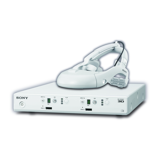
Device Components The HMI-3000MT Head Mounted Image Processor Unit is supplied with the HMS-3000MT Head Mounted Display System. In addition to the HMI-3000MT, the HMS-3000MT system also includes the HMM-3000MT Head Mounted Monitor and the HMO-CA50M Head Mounted Display Cable. -
Page 16: Parts Identification
In such cases, Use only the dedicated HMO-CA50M connection cable to connect the HMI-3000MT and HMM-3000MT. the dot (SUB) at the bottom right does not light. For details, see “Selecting the Input Signal” (page 27). - Page 17 Rear Equipotential grounding terminal • DVI-D 1(2D) output connector Equalizes potential for all devices connected to the unit. Connects to a monitor or another image processor unit, and outputs DVI signals for 2D or 3D video. When B t INPUT connectors outputting the left and right eye videos of a 3D video via •...
- Page 18 Do not touch the patient and the pin of the DC connector at the same time. The pin of the DC connector applies a voltage of 24 V, which may harm the patient. Connect the 24 V DC power cable here. Use a Hosiden–manufactured connector to connect.
-
Page 19: Head Mounted Monitor
If the unit is dropped and becomes damaged or operates abnormally, cease operating the unit and request repair Caution from your Sony service representative. For details on menu operations, see “Modifying Settings” A Front pad (page 28). - Page 20 Front pad angle adjustment switch Front pad lock lever P Display cable connector Q Cable relay box Connects to the image processor unit via the display cable. Caution Use only the dedicated HMO-CA50M connection cable to connect the HMI-3000MT and HMM-3000MT. Parts Identification...
-
Page 21: Operation
Operation Mounting the Head Mounted Monitor Connections Note You will not be able to see your surroundings when the Connect the DC power cable of the AC adaptor to the unit is mounted. We recommend reading the “Mounting DC IN connector on the image processor unit. the Head Mounted Monitor”, “Configuring Initial Settings”, and “Operating the Image Processor Unit”... -
Page 22: Mounting
Mounting Release the headband lock switches on the left and right sides of the headband, and extend the headband. Tilt the head mounted monitor forward so that the display is directly in front of your eyes. Make sure that rear band does not shift away from the position at the back of your neck. - Page 23 Tighten the rear band while holding the head • If the rear band is not positioned properly at the mounted monitor with your other hand. back of your neck, displacement may occur. Repeat the procedure from step 2. Note Tips Excessive tightening of the rear band can result in discomfort and head pain during prolonged use.
-
Page 24: Adjusting For Comfort
To adjust the angle of the front pad Notes • Attach the clip so that there is sufficient slack in the connection cable. Providing slack will prevent your neck from being pulled backward should your foot get caught in the display cable, for example. •... -
Page 25: Correcting Displacement
Correcting Displacement Removing the Head Mounted Monitor If the head mounted monitor shifts during a medical procedure, use one of the following methods to reposition Loosen the rear band, and then remove the head mounted it without contaminating your hands. monitor. -
Page 26: Configuring Initial Settings
Read the instructions that appear on the screen. Configuring Initial After confirming its content, press the MENU or B button. Settings Check the “I” mark and horizontal line displays. Configure settings for the head mounted monitor’s Confirm that the horizontal line intersects each of the display. -
Page 27: Operating The Image Processor Unit
When a remote controller is connected, control signal Operating the Image inputs perform the same function as the INPUT button and allow you to switch the input signal. Processor Unit Holding down the INPUT button resets the input mode to “1.”... -
Page 28: Modifying Settings
Press the MENU button on the head mounted Modifying Settings monitor. Use the v/V buttons to select a setting category, and then press the MENU button. Menu Operations Use the v/V buttons to select a setting menu, and then press the MENU button. You can access the setup menu at any time to change or adjust the unit’s various settings. - Page 29 Display Back Returns to the previous menu. Picture Mode Vivid: Produces vivid colors and sharp contrast. The [Picture Mode] you select Standard: Emphasizes a natural picture to produce a standard quality for a variety of video here can be adjusted in detail sources.
- Page 30 Language setting Selects the language used for menus and other interface elements. Prolonged viewing warning On: Displays a warning after the unit is left on continuously for 6 hours. Off: Disables this function. Startup viewer warning On: Displays a startup warning when the unit is turned on. Off: Disables this function.
-
Page 31: Miscellaneous
Miscellaneous Reattaching the Pads If the front pad detaches Push in the pad while paying attention to its orientation. Insert the rails on the top pad attachment board into the grooves in the top pad. If the side pads detach Push in the pads while paying attention to their orientation. -
Page 32: Troubleshooting
• If the external device is connected to this unit via a signal switcher, connect the device directly to this unit. For details, refer to the instructions for use supplied with the device. • Always use the dedicated HMO-CA50M display cable. For details, contact your Sony service representative. - Page 33 • If the indicator blinks twice every 3 seconds, the head mounted monitor, image processor image processor unit blinks unit, or cables may be damaged. For details, contact your Sony service representative. (orange) continuously. • If the indicator blinks three times every 3 seconds, the image processor unit is overheated.
-
Page 34: Error Messages
A fan error has occurred. If an object is caught in the fan, remove the object. Press the on/standby button to turn off the unit, and then turn it on again. If this error persists, contact your Sony service representative. Error Messages... -
Page 35: Specifications
Output signal Input signal is output as-is. Note that the Specifications following signals are not supported. DVI signals: • Signals with HDCP (also not output to the HMM-3000MT) General • Signals with HDMI functions Power requirement • Signals with resolution higher than 24 V DC (supplied from AC adaptor) Full HD Input current... -
Page 36: License And Trademark Notice
OR AFTER EXPIRATION OF THE WARRANTY, OR FOR ANY OTHER REASON WHATSOEVER. • SONY WILL NOT BE LIABLE FOR CLAIMS OF ANY KIND MADE BY USERS OF THIS UNIT OR MADE BY THIRD PARTIES. • SONY WILL NOT BE LIABLE FOR THE... - Page 37 REF. 176...