Table of Contents
Quick Links
Table of Contents
Troubleshooting

Related Manuals for HP 5305 B


Summary of Contents for HP 5305 B
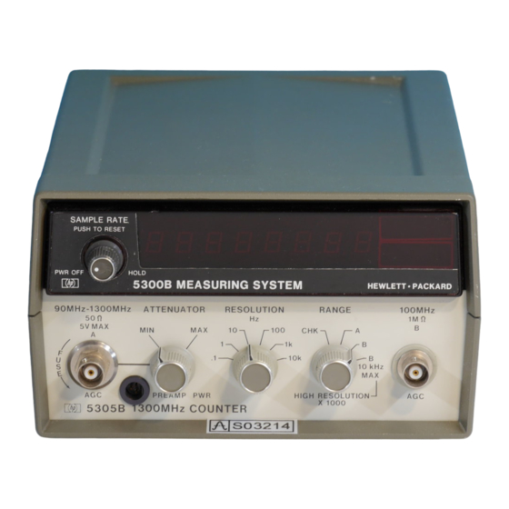
- Page 1 O P E R A T I N G A N D S E R V I C E M A N U A L 1300 MHz COUNTER 5305 B...
- Page 2 CERTIFICATION Hewlett-Packard Company certifies that this instrument met its published specifications at the time of shipment from the factory. Hewlett-Packard Company further certifies that its calibration measurements are traceable to the United States National Bureau of Standards, to the extent allowed by the Bureau's calibration facility, and to the calibration facilities of other International Standards Organization members WARRANTY AND ASSISTANCE This Hewlett-Packard product is warranted against defects in materials and workmanship for...
- Page 3 Measurement System Manual. 5305A instruments are documented in a separate manual. NEWER INSTRUMENTS This section with enclosed "Manual Changes" sheet applies directly to HP Model 5305B 1300 MHz Counters having Serial Prefix numbers above 1616A. OLDER INSTRUMENTS Subsection VII of this document contains information pertinent to all older instruments.
-
Page 4: Table Of Contents
Model 5305B Table of Contents TABLE OF CONTENTS Section Page I X E 5305B 1300 MHz Counter Subsection GENERAL INFORMATION ..................9E-1-1 9E-1-1. Scope of Manual..................9E-1-1 9E-1-3. Description .................... 9E-1-1 9E-1-6. Instrument Identification ............... 9E-1-2 9E-1-8. Equipment Supplied ................9E-1-2 9E-1-10. - Page 5 Model 5305B Table of Contents List of Tables and Figures TABLE OF CONTENTS (Cont'd) Subsection Page MANUAL CHANGES .……..................9E-7-1 9E-7-1. ManualChanges ...................9E-7-1 9E-7-3. NewerInstruments ................9E-7-1 VIII CIRCUIT DIAGRAMS....................9E-8-1 9E-8-1. Introduction..................9E-8-1 LIST OF TABLES Table Page 9E-1-1. Specifications ......................9E-1-3 9E-1-2. Recommended Test Equipment..................9E-1-4 9E-3-1.
-
Page 6: General Information
Model 5305B General Information SECTION I XE 5305B 1300 MHz COUNTER SUBSECTION I GENERAL INFORMATION 9E-1-1. SCOPE OF MANUAL SECTION VI REPLACEABLE PARTS provides a complete list of the counter's replaceable parts and information for ordering parts. 9E-1-2. This manual provides operating and service information for the Hewlett-Packard Model 5305B 1300 MHz Counter. -
Page 7: Instrument Identification
Model 5305B General Information 9E-1-10. ACCESSORIES AVAILABLE The 5305B is applicable to mobile communication bands in addition to VHF and UHF TV transmissions plus TACAN/DME and ATC radar transponders. 9E-1-11. For high-sensitivity UHF applications, the 10855A Preamplifier can be used with the 5305B. The 10855A covers the 2 MHz to 1.3 GHz range with a gain of 9E-1-5. - Page 8 Model 5305B General Table 9E-1-1. Specifications FREQUENCY MEASUREMENT INPUT CHANNEL A (CW OR BURST) Range: 90 MHz to 1300 MHz, prescaled by 16 RESOLUTION (SELECTABLE): Normal Mode (50 Hz to 1300 MHz): 0.1 Hz to Sensitivity: 20 mV rms 10000 Hz in decade steps corresponding to gate times of 10 sec to 0.0001 sec in decade steps on channel B Impedance: 50Ω...
- Page 9 Model 5305B General Information Table 9E-1-2. Recommended Test Equipment Instrument Required Characteristics Recommended Type Oscilloscope 50 MHz Bandwidth HP 180A Vertical Plug-In 50 mV/div Sensitivity HP 1801A Time Base Plug-In 50 MHz Bandwidth HP 1821A Sampling Plug-In 1000 MHz HP 1810A...
-
Page 10: Installation
The 5310A Battery Pack typically provides 5 dependable custom packaging on short notice. Here is one hours of portable operating time before recharging. Tables recommended packaging method: 1-2 and 1-4 in 5300 portion of the manual lists the HP 5310A Battery Pack available accessory. -
Page 11: Operation
Model 5305B Operation SECTION IX E 5305B 1300 MHz COUNTER SUBSECTION III OPERATION 9E-3-8. The frequency range of Channel B depends on the 9E-3-1. INTRODUCTION mode of operation - normal or high resolution. In the normal mode, Channel B covers 50 Hz to 100 MHz. With 9E-3-2. -
Page 12: 3-11. 1300 Mhz Channel Input Levels
5V rms. Fuse is located inside jack. Use a shunted by less than 40 pF. Channel is ac coupled. BNC connector as a wrench to remove and tighten the fuse jack. Replacement HP part number for fuse is 2110-0301. RANGE switch. Allows selection of either of the two input channels or the self-check mode. - Page 13 Model 5305B Operation Figure 9E-3-3. Self-Check Measurements 1. Apply input power to 5300 ac receptacle. 2. Turn counter on with 5300 SAMPLE RATE control. Adjust SAMPLE RATE for minimum display time (full ccw). 3. Set RANGE switch to CHK position. Display is a function of RESOLUTION switch.
- Page 14 Model 5305B Operation Figure 9E-3-4. 100 MHz Channel Frequency Measurements 1. Apply power to 5300 ac receptacle. 2. Turn counter on with 5300 SAMPLE RATE control. 3. Set RANGE switch to B position. 4. Connect input signal to 100 MHz jack. 5.
- Page 15 Model 5305B Operation Figure 9E-3-5. 90 MHz -1300 MHz Channel Frequency Measurements 1. Apply input power to ac receptacle. 2. Turn counter on with 5300 SAMPLE RATE control. 3. Set RANGE switch to A position. 4. Set RESOLUTION switch to 10K. 5.
-
Page 16: Theory Of Operation
Model 5305B Theory of Operation SECTION IX E 5305B 1300 MHz COUNTER SUBSECTION IV THEORY OF OPERATION 9E-4-1 INTRODUCTION. The low source-to-drain impedance (50Ω) shunts resistor R12. The signal passes unattenuated through Q3 to amplifier U6C. The output at U6B(6) feeds the signal through R33 and 9E-4-2. -
Page 17: 4-16. Frequency Multiplier
Model 5305B Theory of Operation This occurs for each scan of the display. When the 9E-4-14. In the Channel B mode, for example, the measurement ends, the XFER line enables U4 and new data operation is as follows. Once the sample rate runs down enters the latch with the next clock pulse from U11(4). - Page 18 Model 5305B Theory of Operation 9E-4-20. Assume, however, the channel B frequency It is important to remember that the frequency/tuning increases. This causes the negative pulses at U22(1) to voltage (U23 pin 6) is a negative relationship. That is, the arrive a little earlier than before, arriving ahead of the lower the tuning voltage, the higher the frequency.
-
Page 19: 4-30. 1300 Mhz ÷ Circuit
Model 5305B Theory of Operation 9E-4-30. 1300 MHz ÷ Circuit 9E-4-27. This puts a step in the loop bandwidth at about 300 Hz input, increasing loop bandwidth drastically above 300 Hz. (Higher loop bandwidth is allowable at higher input 9E-4-31. The A2 board amplifies the Channel A signal and frequencies.) This greatly reduces acquisition time for a 10 then divides it by four before sending it to A1 via J2(9). -
Page 20: Maintenance
Model 5305B Maintenance SECTION IX E 5305B 1300 MHz COUNTER SUBSECTION V MAINTENANCE c. When latches are fully extended rearward, the 5300 9E-5-1 INTRODUCTION and 5305B cast housings should be separated by about 1/8-inch. 9E-5-2. This subsection contains maintenance information for Model 5300/5305B 1300 MHz Counter. - Page 21 Model 5305B Maintenance Figure 9E-5-1. Separation Procedure STEP A STEP B 9E-5-2...
- Page 22 Perform Self-Check procedure, Figure 9E-3-3. 2. CHANNEL A Obtain the following test equipment: HP 8660B/86602A Synthesized Signal Generator a. On 5305B, set RANGE to A, RESOLUTION to 1K, and ATTENUATOR to MIN. b. Set signal generator to 90 MHz at 20 mV.
- Page 23 Model 5305B Maintenance PERFORMANCE CHECK TEST CARD Hewlett-Packard Model 5305B Test Performed by: 1300 MHz COUNTER Serial No. Date: Description Check ٱ SELF CHECK ٱ CHANNEL A ٱ Sensitivity (20 m V) ٱ Frequency Range (90-1300 MHz) ٱ Attenuator ٱ CHANNEL B ٱ...
-
Page 24: 5-15. Adjustments
Model 5305B Maintenance 9E-5-14. INTEGRATED CIRCUIT REPLACEMENT. Two b. Set A2R13 and A1R71 to full ccw. Set A2R22 to mid- methods are recommended for removing integrated circuits: range. c. Connect 5300B/5306A voltmeter positive lead to J2 pin 5 and negative lead to rear panel. a. -
Page 25: 5-19. Channel B Adjustments
HP 651B Test Oscillator c. Set 651B Test Oscillator to 50 Hz at 3V rms and d. HP 8660B/86602A Synthesized Signal Generator connect directly to 100 MHz input on 5305B. d. Measure AGC voltage at TP A with 5300B/5306A 9E-5-25. -
Page 26: 5-27. 1300 Mhz Channel Troubleshooting
Model 5305B Maintenance 9E-5-32. The following table shows the display results 9E-5-27. 1300 MHz Channel Troubleshooting when one of U4's outputs is stuck in one logic state. 9E-5-28. Set the RESOLUTION switch to 1 kHz and Important: set RESOLUTION switch to 10 kHz and use the RANGE switch to A. - Page 27 Model 5305B Maintenance 9E-5-37. If there is no indication at U21(9), connect the c. Check Loop Amplifier U23. For a 1 kHz input U23(6) scope to U24(9) and check for the following sawtooth should be about +9V to + 10V. If it is + 11 V or voltage at the output frequency.
- Page 28 Model 5305B Maintenance 9E-5-40. If the reserve is true, i.e., the frequency at U22(3) is All 8's should show in the display (5300B) for 1/10 second, greater than U22(1), then U22(2) should pulse low (or stay then 0's until new measurement displayed at end of gate time. low if nothing at pin 1).
-
Page 29: Replaceable Parts
Model 5305B Replaceable Parts SECTION IX E 5305B 1300 MHz COUNTER SUBSECTION VI REPLACEABLE PARTS 9E-6-1. INTRODUCTION 9E-6-3. ORDERING INFORMATION 9E-6-4. To obtain replacement parts, address order to 9E-6-2. This subsection contains information for ordering your local Hewlett - Packard Sales and Service Office (see replacement parts. - Page 30 Model 5305B Replaceable Parts ABBREVIATIONS (CONTINUED) ENCAP = encapsulated = minute (time) = peak inverse voltage = thin-film transistor = external …’ = minute (plane angle) = peak = toggle = farad MINAT = miniature = phase lock = thread = field-effect transistor = millimeter = phase lock oscillator...
- Page 31 Model 5305B Replaceable Parts Table 9E-6-1. Replaceable Parts Reference HP Part Description Mfr Part Number Designation Number Code 05305-60005 BOARD ASSY, LOGIC 28480 05305-60005 A1C1 0160-4084 CAPACITOR-FXD .1UF +-20% 50WVDC CER 28480 0160-4084 A1C2 0160-4084 CAPACITOR-FXD .1UF +-20% 50WVDC CER...
- Page 32 Model 5305B Replaceable Parts Table 9E-6-1. Replaceable Parts (Cont'd) Reference HP Part Description Mfr Part Number Designation Number Code A1CR21 1901-0535 DIODE-SCHOTTKY 28480 1901-0535 A1CR22 1910-0016 DIODE-GE 60V 60NA 1US DO-7 28480 1910-0016 A1CR23 1901-0028 DIODE-PWR RECT 400V 750MA DO-29...
- Page 33 Model 5305B Replaceable Parts Table 9E-6-1. Replaceable Parts (Cont'd) Reference HP Part Description Mfr Part Number Designation Number Code A1R47 1810-0041 NETWORK-RES 9-PIN-SIP .15-PIN-SPCG 28480 1810-0041 A1R48 0683-5115 RESISTOR 510 5% .25W FC TC=-400/+600 01121 C85115 A1R49 0683-1025 RESISTOR 1K 5% .25W FC TC=-400/+600...
- Page 34 Model 5305B Replaceable Parts Table 9E-6-1. Replaceable Parts (Cont'd) Reference HP Part Description Mfr Part Number Designation Number Code A1U16 1826-0174 IC MC 3302 COMPARATOR 28480 1826-0174 A1U17 1820-0817 IC-DIGITAL MC10131P ECL DUAL D-M/S 04713 MC10131P A1U18 1820-0584 IC-DIGITAL DM74L02N TTL L QUAD 2 NOR...
- Page 35 Model 5305B Replaceable Parts Table 9E-6-1. Replaceable Parts (Cont'd) Reference HP Part Description Mfr Part Number DesignatIon Number Code A2R21 0698-4132 RESISTOR 62 5% .125W CC TC=-270/+540 01121 886205 A2R22 2100-1986 RESISTOR-TRMR 1K 10% C TOP-ADJ 1-TURN 30983 ET50W102 A2R23 0698-3442 RESISTOR 237 1% .125W F TC-0+-100...
- Page 36 Model 5305B Replaceable Parts Figure 6-1. Details of Input Connector J1 and Fuse Mounting Table 9E-6-2. Manufacturers Code List Mfr No. Manufacturer Name Address Zip Code 01121 Allen-Bradley Co Milwaukee, WI 53212 01295 Texas Instr Inc Semicond Cmpnt Div Dallas, TX 75231 04713 Motorola Semiconductor Products...
- Page 37 Model 5305B Manual Changes and Options SECTION IX E 5305B 1300 MHz COUNTER SUBSECTION VII MANUAL CHANGES 9E-7-3. NEWER INSTRUMENTS 9E-7-1. MANUAL CHANGES 9E-7-4. As changes are made, newer instruments may 9E-7-2. Section IX E applies directly to model 5305B have serial number prefixes not listed in Section IX E.
- Page 38 Model 5305B Circuit Diagrams SECTION IX E 5305B 1100 MHz COUNTER SUBSECTION VIII CIRCUIT DIAGRAMS 9E-8-1. INTRODUCTION c. Component location views of the printed-circuit boards. 9E-8-2. This subsection of the manual contains the d. Schematic diagrams of the counter following information: 9E-8-3.
- Page 39 Model 5305B Circuit Diagrams Table 9E-8-1. Counter Signal List (Continued) PIN NO. SIGNAL NAME DESCRIPTION PRINT Low signal provides print command to rear panel connector on mainframe. Low signal transfers data to display. High signal stores data. TRANSFER 1 MHz TIME BASE INPUT TIME BASE SELECT A Time base select code A, B, and C determines the time base TIME BASE SELECT B...
- Page 40 Model 5305B Schematic Diagrams Part of Figure 8-1. Channel B and Frequency Multiplier Circuits, Schematic Diagram Input Signal: 9 kHz at 1V rms Oscilloscope: HP 180A/1801A/1821A with 10:1 probe Oscilloscope Settings: DISPLAY: ALT (Unless otherwise stated) POLARITY: + Coupling: A.C.
- Page 41 Model 5305B Schematic Diagrams Part of Figure 8-1. Channel B and Frequency Multiplier Circuits, Schematic Diagram (Cont'd) 9E-8-4...
- Page 42 CAPACITANCE IN PICOFARADS INDUCTANCE IN MICROHENRIES 3. +17VB -5VA AND +5VB IS SWITCHED FROM A1S1 A1 TABLE OF ACTIVE ELEMENTS Ref. Desig. HP Part No. Mfr or Industry Part No. CR1, 10, 16, 20, 22 1910-0016 CR2, 4, 5, 7 1901-0179...
- Page 44 Model 5305B Schematic Diagrams Part of Figure 8-2. Channel A and Logic Board Circuits, Schematic Diagram .05V/DIV, 2 µS/DIV, AC/ALT .2V/DIV, .5 ms/DIV, DC/ALT Note: Waveforms 1 thru 10 taken with 1 MHz input and RESOLUTION switch set to .1 Hz. Waveforms 11 thru 16 taken with 100 MHz input. .05V/DIV, 5 µs/DIV, AC/ALT .2V/DIV, .5 ms/DIV, DC/ALT .05V/DIV, .1 µs/DIV, DC/ALT MAG-X10...
- Page 45 Model 5305B Schematic Part of Figure 8-2. Channel A and Logic Board Circuits, Schematic Diagram (Cont'd) .05V/DIV, .1 µs/DIV, DC/ALT .05V/DIV, .1 µs/DIV, AC/ALT A2 1.3 GHz AMPLIFIER DC VOLTAGE MEASUREMENTS WITH NO INPUT SIGNAL ATTN: MIN RANGE: 1300 MHz ATTN: MAX CR5 Anode 10.5V...
- Page 46 Model 5305B Schematic Diagrams Part of Figure 8-2. Channel A and Logic Board Circuits, Schematic Diagram (Cont'd) A2 TABLE OF ACTIVE ELEMENTS Ref. Desig. HP Part No. Mfr or Industry Part Nc. CR1, 7 1902-0032 SZ-10939-107 CR2, 4 1901-0050 1902-3171...