Quick Links
This manual contains text, diagrams and explanations which will guide the reader in the correct installation
and operation of the FX
attempting to install or use the unit. Further information can be found in the FX series PLC hardware man-
uals.
If in doubt at any stage during the installation of the FX
professional electrical engineer who is qualified and trained to the local and national standards.
Note's on the symbology used in this manual
At various times through out this manual certain symbols will be used to highlight points of infor-
mation which are intended to ensure the users personal safety and protect the integrity of the
equipment. Whenever any of the following symbols are encountered, its associated note must be
read and understood. Each of the symbols used will now be listed with a brief description of its
meaning.
Hardware warnings
1) Indicates that the identified danger WILL cause physical and property damage.
2) Indicates that the identified danger could POSSIBLY cause physical and property damage.
Guidelines for the safety of the user and protection of the FX
POWER SUPPLY UNIT
•
This manual has been written to be used by trained and competent personnel. This is defined
by the European directives for machinery, low voltage and EMC.
•
If in doubt at any stage during the installation of the FX
sional electrical engineer who is qualified and trained to the local and national standards. If in
doubt about the operation or use of the FX
Electric distributor.
•
Under no circumstances will Mitsubishi Electric be liable or responsible for any consequential
damage that may arise as a result of the installation or use of this equipment.
•
All examples and diagrams shown in this manual are intended only as an aid to understand-
ing the text, not to guarantee operation. Mitsubishi Electric will accept no responsibility for
actual use of the product based on these illustrative examples.
•
Owing to the very great variety in possible application of this equipment, you must satisfy
yourself as to its suitability for your specific application.
1. INTRODUCTION
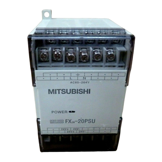
The DC power supply unit FX
•
Power supply of 24V DC power type PLC
•
Power supply of special extension block of PLC
•
Power supply of sensor connected to input of PLC
•
Power supply of DC load connected to output of PLC
•
Power supply of display unit such as graphic operation terminal (GOT)
-20PSU DC power supply unit. It should be read and understood before
2N
-20PSU is available as the following applications.
2N
FX
-20PSU DC POWER SUPPLY UNIT
2N
USER'S MANUAL
-20PSU DC power supply unit always consult a
2N
2N
-20PSU please consult the nearest Mitsubishi
2N
JY992D85101A
-20PSU DC
2N
-20PSU always consult a profes-

Related Manuals for Mitsubishi Electric JY992D85101A


Summary of Contents for Mitsubishi Electric JY992D85101A
- Page 1 All examples and diagrams shown in this manual are intended only as an aid to understand- ing the text, not to guarantee operation. Mitsubishi Electric will accept no responsibility for actual use of the product based on these illustrative examples.
-
Page 2: External Dimension
2. EXTERNAL DIMENSION 2-φ4.5 (0.18) 52(2.05) Unit:mm(inches) AC85 to 264V DIN rail:35mm(1.38) POWER 24V+ 24V- 24V+ 24V- 75(2.95) 60(2.36) Mass: Approximately 0.3 kg 24V+ 24V- Outer color: Munsell 0.08GY/7.64/0.81 24V+ 24V- 3. GENERAL SPECIFICATIONS Item Description Operating Tempera- 0 to 55 °C (32 to 131 °F) ture Storage Temperature -20 to 70 °C (-4 to 158 °F) - Page 3 4. PERFORMANCE SPECOFOCATIONS Input voltage 85 to 264V AC Frequency 50/60Hz Input Fuse rating 3.15A (built in) Rush current 60A/200V AC maximum Output voltage 24V DC ± 10% 2A (maximum), 0.2A (minimum) Output current (Derating is performed if ambient temperature exceeds 40 °C.)*1 Output Ripple noise 500mVp-p or less...
-
Page 4: Cautions On Installation
5. INSTALLATION Cautions on installation • Use the unit in the environment for the general specifications described in Section 3 in the manual. Never use the unit in a place with dust, soot, conductive dusts, corrosive gas or flammable gas, place exposed to high temperature, dew condensation, rain and wind, or in a place exposed to vibration or impact. - Page 5 6.1 When FX -20PSU is connected to 24V DC power type PLC Source inputs (-ve S/S) Sensor 1 Sensor 2 85 to 264V AC Class 3 grounding 24V 0V -20PSU 24+ 24- Sink inputs (+ve S/S) Sensor 1 Sensor 2 85 to 264V AC Class 3 grounding...
-
Page 6: Troubleshooting
Manual revision : A Date : FEB. 2000 HEAD OFFICE : MITSUBISHI DENKI BLDG MARUNOUTI TOKYO 100-8310 TELEX : J24532 CABLE MELCO TOKYO HIMEJI WORKS : 840, CHIYODA CHO, HIMEJI, JAPAN Effective FEB. 2000 JY992D85101A Specifications are subject to change without notice...