Table of Contents
Quick Links
Table of Contents
Troubleshooting

Related Manuals for GE Dash Port 2

Summary of Contents for GE Dash Port 2
- Page 1 ® Dash Port 2 Docking Station Service Manual 2000966-138 Revision A...
- Page 2 Listed below are GE Medical Systems Information Technologies’ trademarks used in this document. All other trademarks contained herein are the property of their respective owners. DASH, SAM, and UNITY NETWORK are trademarks of GE Medical Systems Information Technologies registered in the United States Patent and Trademark Office.
-
Page 3: Table Of Contents
Compatible Remote Displays ........2-12 Revision A Dash Port 2 Docking Station 2000966-138... - Page 4 Remote Display (Option) Test ........4-16 Dash Port 2 Docking Station...
- Page 5 Remote Display ...........A-3 Revision A Dash Port 2 Docking Station 2000966-138...
- Page 6 Computer-Grade Displays ......... . .B-3 Required Specifications for Computer/Flat Panel Displays ....B-4 Dash Port 2 Docking Station Revision A...
-
Page 7: Introduction
Introduction Revision A Dash Port 2 Docking Station 2000966-138... - Page 8 For your notes Dash Port 2 Docking Station Revision A 2000966-138...
-
Page 9: Manual Information
See the operation instructions for the instructions necessary to operate the equipment safely in accordance with its function and intended use. Manual Conventions The Dash Port 2 docking station will be referred to as the docking station in this manual. Intended Audience This manual is intended for service representatives and technical personnel who maintain, troubleshoot, or repair this equipment. -
Page 10: Safety Information
Introduction: Safety Information Safety Information Responsibility of the Manufacturer GE is responsible for the effects of safety, reliability, and performance only if: Assembly operations, extensions, readjustments, modifications, or repairs are carried out by persons authorized by GE. The electrical installation of the relevant room complies with the requirements of the appropriate regulations. -
Page 11: Hazard Definitions
Indicates a potential hazard or unsafe practice which, if not avoided, could result in minor personal injury or product/property damage. NOTE Provides application tips or other useful information to assure that you get the most from your equipment. Revision A Dash Port 2 Docking Station 2000966-138... -
Page 12: Equipment Symbols
Alternating Current (AC) Medical Equipment With respect to electric shock, fire and mechanical hazards only in accordance with UL 2601-1, and CAN/CSA C22.2 NO. 601.1. 001A, 002A, 003A, 030A 4P41 Dash Port 2 Docking Station Revision A 2000966-138... -
Page 13: Service Requirements
Any unauthorized attempt to repair equipment under warranty voids that warranty. It is the user’s responsibility to report the need for service to GE or to one of their authorized agents. Failure on the part of the responsible individual, hospital, or... -
Page 14: Equipment Identification
### ## ## #### # # Description product code year manufactured fiscal week manufactured production sequence number manufacturing site miscellaneous characteristic 1. The product code for the Dash Port 2 docking station is AAA. Dash Port 2 Docking Station Revision A 2000966-138... -
Page 15: Equipment Overview
Equipment Overview Revision A Dash Port 2 Docking Station 2000966-138... - Page 16 For your notes Dash Port 2 Docking Station Revision A 2000966-138...
-
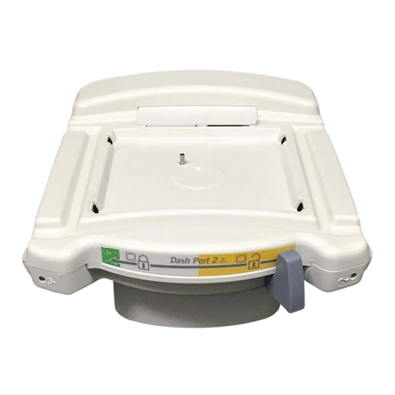
Page 17: Equipment Description
A steady green color indicates the docking station has established communication with the monitor. amber LED A flashing amber color indicates that the docking station and the Dash monitor are not compatible. See Chapter 5, “Troubleshooting” Revision A Dash Port 2 Docking Station 2000966-138... - Page 18 See “Compatible Auxiliary Devices” on page 2- AC power connector Insert AC power cable. See “Power Requirements” page A-3. equipotential lug Provides a means of maintaining equipotential ground reference between connected devices. Dash Port 2 Docking Station Revision A 2000966-138...
-
Page 19: Optional Components
“Other Components” on page 6-14 for video cables and video cable extenders. GCX Pedestal Mount The GCX pedestal mount allows you to mount the docking station on a flat table-top surface. 031A Revision A Dash Port 2 Docking Station 2000966-138... -
Page 20: Theory Of Operation
Equipment Overview: Theory of Operation Theory of Operation Overview The Dash Port 2 docking station provides an external remote (640x480 VGA) video capability, two additional AUX ports, Ethernet connection (10BaseT), and AC power to a compatible Dash monitor. The mechanical hardware is intended to be used in conjunction with the Dash Port Interface/Isolation PCB to provide a means to quickly and reliably attach/detach the Dash family of transport monitors. -
Page 21: Block Diagram
Regulator Limit Switched +9-18V Fault Power AC Power Regulator Indicator LED AC Power Power AC Power Power AC Power Power Fuse Fuse Connector AC Power Connector Supply 2A @ 110V (male) (female) Revision A Dash Port 2 Docking Station 2000966-138... -
Page 22: Controls And Indicators
A steady green color indicates the docking station has established communication with the monitor. Amber LED A flashing amber color indicates that the docking station and the Dash monitor are not compatible. See Chapter 5, “Troubleshooting” Dash Port 2 Docking Station Revision A 2000966-138... -
Page 23: Equipment Compatibility
Dash 2000 (version 3 or later software) Dash 3000 (version 1 software) Dash 3000/4000 (version 2 software) Dash 3000/4000 (version 3 and version 4 software) Dash 3000/4000 (version 5 or later software) Revision A Dash Port 2 Docking Station 2000966-138... -
Page 24: Compatible Auxiliary Devices
Please contact your local GE Medical Systems Information Technologies Sales Representative for product availability. Supported GE Auxiliary Devices The following GE devices are supported by the both the monitor and by the docking station’s AUX connectors. DT-7000 Transceiver Patient Data Management System. - Page 25 See the documentation provided with Remote Alarm Box to properly configure the Remote Alarm Box for use with a docking station. Remote control Nellcor N-395 pulse oximeter Unity Network ID (auto- association cable) Revision A Dash Port 2 Docking Station 2-11 2000966-138...
-
Page 26: Compatible Remote Displays
Equipment Overview: Equipment Compatibility Compatible Remote Displays The Dash Port 2 docking station is currently available with the following GE remote displays: 15-inch, medical-grade, flat panel, color LCD display 18-inch, medical-grade, flat panel, color LCD display Off-the-shelf (computer-grade) displays are also compatible. See “Appendix B –... -
Page 27: Installation
Installation Revision A Dash Port 2 Docking Station 2000966-138... - Page 28 For your notes Dash Port 2 Docking Station Revision A 2000966-138...
-
Page 29: Requirements
DROP HAZARD — Verify the equipment mount used to hold both the docking station and the patient monitor will support a minimum of 30 pounds (13.60 kg). Otherwise, serious injury or death could result. Revision A Dash Port 2 Docking Station 2000966-138... -
Page 30: Tools
The video cable should NOT exceed 45.72 meters (150 feet) in length. The remote display does NOT provide audible patient or system alarms. Therefore, GE recommends that you mount the remote display in a location that allows the clinician to see and hear the patient and system alarms that originate from the patient monitor. -
Page 31: Equipment Mounts
Equipment Mounts Mounting Options 127( GE strongly recommends not using a non-locking variable height wall mount arm with this product. The weight of the monitor keeps the mounting arm in position. Removing the monitor from the mount could cause the mounting arm to unexpectedly spring upwards. - Page 32 2. Mount, pn 2007059-001, includes triangular Pedestal base[~30.5cm (12in)], Tilt/Swivel head w/3.2cm (1.25in) pipe, 12.7cm (5in) Mounting plate and combination Counter Mt/Slide Plate Adapter. 7.6 cm (3.0 in) Dash Port 2 Docking Station Revision A 2000966-138...
- Page 33 (4.0 in) (5.0 in) 5. Maximum allowable supported weight: 31.1 cm 132.1 TO 152.4 cm (12.25 in) 43.8 cm (52.0 TO 60.0 in) 13.6 kilograms (30 pounds) (17.25 in) FROM FLOOR 2002746-002 Revision A Dash Port 2 Docking Station 2000966-138...
-
Page 34: Gcx Mounting Procedure
2. Pull down and hold onto the locking pin and continue to slide the docking station onto the GCX mount. Then let go of the locking pin. 033A 3. Verify the locking pin clicks into position to secure the docking station to the GCX mount. Dash Port 2 Docking Station Revision A 2000966-138... -
Page 35: Connections
When connecting an auxiliary device, see the documentation that was provided with the device and the Dash Patient Monitor Operator’s Manual for cable and configuration requirements. Revision A Dash Port 2 Docking Station 2000966-138... -
Page 36: Mount The Dash Monitor
The security lever should move automatically to the central position and lock the monitor into place. 4. Try to pivot the monitor from front to back to verify it is secure. 3-10 Dash Port 2 Docking Station Revision A 2000966-138... - Page 37 3. Verify a green-colored communication indicator is illuminated on the docking station Some Dash 2000 monitors do not support the docking station’s Ethernet or auxiliary communication links. See “Compatible Dash Monitors” on page 2-9. Revision A Dash Port 2 Docking Station 3-11 2000966-138...
-
Page 38: Setup/Configure
If the remote display image is good, no manual adjustments are required. Good Remote Display Image - No Adjustement Required 040A b. If the remote display image is very blurry or cut-off, complete a on page 3-13 “Manual Adjustment” 3-12 Dash Port 2 Docking Station Revision A 2000966-138... - Page 39 Display the Vital Signs NRT on the monitor and on the remote display. b. Complete an auto-adjust (auto-tune) procedure as described in the documentation provided with the remote display. Revision A Dash Port 2 Docking Station 3-13 2000966-138...
-
Page 40: Pm/Install Checkout
Installation: PM/Install Checkout PM/Install Checkout Complete the Electrical Safety Tests and Checkout Procedures identified in Chapter 4, “Maintenance” 3-14 Dash Port 2 Docking Station Revision A 2000966-138... -
Page 41: Maintenance
Maintenance Revision A Dash Port 2 Docking Station 2000966-138... - Page 42 For your notes Dash Port 2 Docking Station Revision A 2000966-138...
-
Page 43: Maintenance Schedule
12 months thereafter, and each time the unit is serviced. Checkout Procedures: Perform the checkout upon receipt of the equipment, every 12 months thereafter, and each time the unit is serviced. Revision A Dash Port 2 Docking Station 2000966-138... -
Page 44: Visual Inspection
Inspect all external connections for loose connectors or frayed cables. Have any damaged connectors or cables replaced by qualified service personnel. Safety labels and inscription on the device are clearly legible. Dash Port 2 Docking Station Revision A 2000966-138... -
Page 45: Cleaning
Wring the excess solution from the cloth. Do not drip any liquid into open vents, switches, plugs, or connectors. Dry the surfaces with a clean lint-free cloth. Revision A Dash Port 2 Docking Station 2000966-138... -
Page 46: Electrical Safety Tests
The sole responsibility rests with the individual or institution using the equipment. GE service personnel may, at their discretion, follow the procedures provided in this manual as a guide during visits to the equipment site. -
Page 47: Power Outlet Test
If other than normal polarity and ground is indicated, corrective action must be taken before proceeding. The results of the following tests will be meaningless unless a properly wired power outlet is used. Revision A Dash Port 2 Docking Station 2000966-138... -
Page 48: Ground (Earth) Integrity
This test normally is only required as a manufacturing production test to receive safety agency compliance (i.e. IEC601-1). Some country agency's do require this test after field equipment repairs (i.e. Germany's DIN VDE 0751 standards). Consult your country/local safety agency if in question. Dash Port 2 Docking Station Revision A 2000966-138... - Page 49 0.2 ohms. When taking this measurement, move the unit’s power cord around. There should be no fluctuations in resistance. Revision A Dash Port 2 Docking Station 2000966-138...
-
Page 50: Ground (Earth) Wire Leakage Current Tests
6. Read the current leakage indicated on DMM. 127( If either reading is greater than the appropriate specification below, the device under test fails. Contact GE Medical Systems Information Technologies Technical Support. 300 µA (0.3 volts on the DMM), and the device under test is powered from 100-120 V/50-60 Hz ... -
Page 51: Enclosure Leakage Current Test
5. Read the current leakage indicated on DMM. 127( If either reading is greater than the appropriate specification below, the device under test fails. Contact GE Medical Systems Information Technologies Technical Support. • 300 µA (0.3 volts on the DMM), and the device under test is powered from 100-120 V/50-60 Hz •... -
Page 52: Test Completion
127( If the reading is greater than the specification below, and the device under test is powered from 100-240 V/50-60 Hz, the device under test fails. Contact GE Medical Systems Information Technologies Technical Support. 100 microamperes (0.1 volts on the DMM), and the device under... -
Page 53: Checkout Procedures
The checkout procedures are written for the test equipment in the following table. If you use test equipment other than those GE recommends, you may need to slightly modify some test steps. -
Page 54: Docking Station Power-Up Tests
7. Verify the AC indicator on the monitor stays illuminated. 127( If the AC LED stays on, but the screen is blank, the monitor is likely in “standby mode” (battery charging). Press the Power button to turn on the monitor. 4-14 Dash Port 2 Docking Station Revision A 2000966-138... -
Page 55: Network Test
4. Verify the REMOTE CONTROL label appears after the appropriate port and the software version for the remote control is 1A. 5. Press each remote control key and verify a beep tone sounds at the monitor. Revision A Dash Port 2 Docking Station 4-15 2000966-138... -
Page 56: Remote Display (Option) Test
3. From the monitor, select MORE MENUS > PATIENT DATA > VITAL SIGNS. 4. Verify the Vital Signs NRT displays correctly on the remote display. “Adjust the Remote Display (Option) Video Signal” on page 3-12. 4-16 Dash Port 2 Docking Station Revision A 2000966-138... - Page 57 Maintenance: Checkout Procedures PM/Repair Log Unit Serial Number: Institution Name: Date Maintenance/Repair Technician Revision A Dash Port 2 Docking Station 4-17 2000966-138...
- Page 58 Maintenance: Checkout Procedures Unit Serial Number: Institution Name: Date Maintenance/Repair Technician 4-18 Dash Port 2 Docking Station Revision A 2000966-138...
-
Page 59: Troubleshooting
Troubleshooting Revision A Dash Port 2 Docking Station 2000966-138... - Page 60 For your notes Dash Port 2 Docking Station Revision A 2000966-138...
-
Page 61: General Fault Isolation
3-12 if the remote display image shows any of the following symptoms: The image on the remote display appears to flicker. Part of the image on the remote display cut-off. Revision A Dash Port 2 Docking Station 2000966-138... -
Page 62: Ac Line Voltage Test
The voltage measurements should be as follows: 1. 120 VAC (± 10 VAC) between either “hot” contact and ground. 2. 210 to 230 VAC between the two “hot” contacts. ❷ ❶ ❶ GROUND Dash Port 2 Docking Station Revision A 2000966-138... -
Page 63: Troubleshooting Procedures
Use a Dash 2000 monitor that has the indicator is NOT illuminated. communication PCB required to interface communication PCB installed. See with the docking station. “Compatible Dash Monitors” on page 2-9. 006A communication PCB Revision A Dash Port 2 Docking Station 2000966-138... - Page 64 The network cable is connected to the Disconnect the network cable from the the Unity Network. monitor instead of the docking station. monitor and reconnect it to the docking The docking station’s illuminated station. communication indicator is green. Dash Port 2 Docking Station Revision A 2000966-138...
- Page 65 The auxiliary device may need to be See the Dash Patient Monitor Operator’s configured to function with a docking Manual and the operator’s manual station. provided with the auxiliary device for configuration recommendations. Revision A Dash Port 2 Docking Station 2000966-138...
- Page 66 If AC power is NOT present at the J2 PCB connection, verify the J2 connector is securely seated. If it is securely seated, then “Replace the Connector Assembly FRU or PCB FRU” on page 6-19. Dash Port 2 Docking Station Revision A 2000966-138...
- Page 67 6-10. Adjust the spring plunger if necessary. 3. If adjusting the spring plunger does not resolve the problem, then “Replace the Connector Assembly FRU or PCB FRU” on page 6-19. Revision A Dash Port 2 Docking Station 2000966-138...
- Page 68 If a mechanism is defective, “Replace the Top Housing FRU” on page 6-18. The locking lever pin or spring are either “Join the Top and Bottom Housings” missing or not installed correctly. on page 6-25. 5-10 Dash Port 2 Docking Station Revision A 2000966-138...
- Page 69 PCB The docking station’s illuminated must be replaced. See, “Replace the communication indicator is amber. Connector Assembly FRU or PCB FRU” on page 6-19. Revision A Dash Port 2 Docking Station 5-11 2000966-138...
- Page 70 The monitor might not be positioned Remove and re-position the monitor. correctly on the docking station to activate the locking mechanism. The Top Assembly FRU has failed. “Replace the Top Housing FRU” page 6-18. 5-12 Dash Port 2 Docking Station Revision A 2000966-138...
- Page 71 1. Remove foreign objects blocking the monitor’s expansion PCB. expansion PCB. 2. Reposition the monitor. The Connector Assembly FRU has failed. See, “Replace the Connector Assembly FRU or PCB FRU” on page 6-19. Revision A Dash Port 2 Docking Station 5-13 2000966-138...
- Page 72 Troubleshooting: Troubleshooting Procedures For your notes 5-14 Dash Port 2 Docking Station Revision A 2000966-138...
-
Page 73: Part Lists, Drawings, And Replacement
Part Lists, Drawings, and Replacement Revision A Dash Port 2 Docking Station 2000966-138... - Page 74 For your notes Dash Port 2 Docking Station Revision A 2000966-138...
-
Page 75: Ordering Parts
If you require additional information or troubleshooting assistance, contact Technical Support. To order parts, contact Service Parts at the address or telephone number listed on the “How to Reach Us...” page found in the front of this manual. Revision A Dash Port 2 Docking Station 2000966-138... -
Page 76: Field Replaceable Units (Frus)
“PCB Board — PN 2013500-004, Rev. A” on page 6-7. 036A, 037A “Hardware and Fasteners” on page 6-8. 127( The hardware and fasteners are included with the 037A top assembly, connector assembly, and the PCB FRUs. Dash Port 2 Docking Station Revision A 2000966-138... -
Page 77: Top Assembly - Pn 2013500-002, Rev. A
Item Description Number ENCL TOP DOCKING STATION DOOR CONNECTOR ASSY LEVERS DOCKING STATION LABEL DASH PORT 2 FRONT PANEL SPACER ACETAL .25 LG SCR MACH PNHD M4X6LG SST W/THD LOCK WASHER M3 PLAIN S/S SCR TAPPING TF M3 X 6 LG PKG BAG CUSHION ZIP 15 X 15 STATIC SHLD BOX MAILER 11.75L 11.00W 2.88H... -
Page 78: Connector Assembly - Pn 2013500-003, Rev. A
Item Description Number ASSY CONNECTOR DOCKING STATION PKG BAG BUBBLE ZIP 8 X 12 ANTI-STATIC BOX MAILER 9.75L 2.88H 7.38W LABEL CARTON FRU - DASHPORT 2 Hardware FRU (See“Hardware and Fasteners” page 6-8. Dash Port 2 Docking Station Revision A 2000966-138... -
Page 79: Pcb Board - Pn 2013500-004, Rev. A
037A Find Item Description Number LED VERT LIGHT PIPE ASSY 235MM PCB ACCESSORY INTERFACE DASH PORT 2 PKG BAG BUBBLE ZIP 6 X 10 ANTI-STATIC BOX MAILER 7.00L 6.00W 2.50H LABEL CARTON FRU - DASHPORT 2 Hardware FRU (See“Hardware and Fasteners”... -
Page 80: Hardware And Fasteners
WASHER LOCK SERRATED F/M-6 SCR MACH PNHD M4X6LG SST W/THD LOCK SCR MACH PNHD M4X10LG SST THD LOCK SCR PH M4X .7X6.0LG SEMS BAG ZIPLOCK CLR 2MIL POLY 5X7 LABEL CARTON FRU - DASHPORT 2 Dash Port 2 Docking Station Revision A 2000966-138... -
Page 81: Interconnection Diagram
Part Lists, Drawings, and Replacement: Interconnection Diagram Interconnection Diagram Revision A Dash Port 2 Docking Station 2000966-138... -
Page 82: Exploded View
Part Lists, Drawings, and Replacement: Exploded View PN 2004740-002, Revision A Exploded View PN 2004740-002, Revision A Page 1 of 2 6-10 Dash Port 2 Docking Station Revision A 2000966-138... - Page 83 Part Lists, Drawings, and Replacement: Exploded View PN 2004740-002, Revision A Page 2 of 2 Revision A Dash Port 2 Docking Station 6-11 2000966-138...
- Page 84 LED VERT LIGHT PIPE ASSY 235MM ASSY LEVERS DOCKING STATION ASSY CONNECTOR DOCKING STATION SPRING CPRSN 7.6 OD X 14.2 LG LABEL DASH PORT 2 FRONT PANEL SCR MACH PNHD M3X6LG SST W/THD LOCK PCB ACCESSORY INTERFACE DASH PORT 2 LABEL DASH PORT RATINGS...
- Page 85 Part Lists, Drawings, and Replacement: Parts List PN 2004740-002, Revision A Find Reference Item Description Number Designator SCR PH M4X .7X6.0LG SEMS LED RT-ANG GREEN LIGHT PIPE ASSY 292MM Revision A Dash Port 2 Docking Station 6-13 2000966-138...
-
Page 86: Other Components
Video Cable, HD15M-HD15F, 4’ (male to female video extender cable) 415301-402 Video Cable, HD15M-HD15F, 10’ (male to female video extender cable) 415301-403 Video Cable, HD15M-HD15F, 25’ (male to female video extender cable) 6-14 Dash Port 2 Docking Station Revision A 2000966-138... - Page 87 2002215-003 Analog Video Cable, 15’ (male to male 15 pin D connector video replacement cable) 2002215-004 Analog Video Cable, 25’ (male to male 15 pin D connector video replacement cable) Revision A Dash Port 2 Docking Station 6-15 2000966-138...
-
Page 88: Disassembly/Assembly Of Frus
127( GE recommends that you assemble the docking station using the NEW fasteners (screws, washers, etc.) provided in the Field Replaceable Unit kit. Some fasteners, like the screws with a thread locking coating, are NOT intended to be re-used more than three times. -
Page 89: Dissassembly Procedures
4. Continue to hold onto the security lever and gently let it slide back into its resting position. 016A 5. Remove the locking lever spring and pin. 044A Revision A Dash Port 2 Docking Station 6-17 2000966-138... - Page 90 Replace the Top Housing FRU “Separate the Top and Bottom Housings” page 6-17. 2. Discard the defective top housing and install the replacement Top Housing FRU. “Join the Top and Bottom Housings” on page 6- 6-18 Dash Port 2 Docking Station Revision A 2000966-138...
- Page 91 Push the light pipes out from the bottom assembly housing. b. Discard the defective light pipes. 049A 6. Use a 10 mm wrench or nut driver to remove the equipotential lug. 046A Revision A Dash Port 2 Docking Station 6-19 2000966-138...
- Page 92 7. Remove the three connector assembly bracket screws from the bottom housing. 025A 8. Lift out the connector assembly. 051A 9. Unclip the two power connectors from the PCB. 056A 10. Remove the five PCB screws. 058A 6-20 Dash Port 2 Docking Station Revision A 2000966-138...
- Page 93 If the connector assembly is defective, dispose of it and install the PCB FRU. a. If the connector assembly is not defective, reinstall the connector assembly. 13. Insert the PCB ribbon cable friction connector. 055A Revision A Dash Port 2 Docking Station 6-21 2000966-138...
- Page 94 16. Start with the center screw and install the three connector assembly bracket screws. 025A 17. If the light pipes are to be replaced, route the light pipes through the bottom housing’s LED opening. 049A 6-22 Dash Port 2 Docking Station Revision A 2000966-138...
- Page 95 19. Gently push the light pipe lens into the lens opening until it is seated. 052A 20. Stabilize the PCB LED connector and gently insert the AC power indicator light pipe. 048A Revision A Dash Port 2 Docking Station 6-23 2000966-138...
- Page 96 Insert the lug into the threaded hole and tighten the lug “Join the Top and Bottom Housings” on page 6- star washer 046A 24. Insert the PCB ribbon cable friction connector. 055A 6-24 Dash Port 2 Docking Station Revision A 2000966-138...
-
Page 97: After Reassembly
“Ground (Earth) Wire Leakage Current “Network Test” on page 4-15. PCB FRU Tests” on page 4-10. “Auxiliary Port Test” on page 4-15. “Enclosure Leakage Current Test” “Remote Display (Option) Test” page 4-11. page 4-16. Revision A Dash Port 2 Docking Station 6-25 2000966-138... - Page 98 Part Lists, Drawings, and Replacement: Disassembly/Assembly of FRUs For your notes 6-26 Dash Port 2 Docking Station Revision A 2000966-138...
-
Page 99: Appendix A - Technical Specifications
Appendix A – Technical Specifications 127( Due to continual product innovation, specifications are subject to change without notice. The following specifications are accurate as of the date of this publication, and pertain to the monitor. Revision A Dash Port 2 Docking Station 2012659-002... - Page 100 For your notes Dash Port 2 Docking Station Revision A 2012659-002...
-
Page 101: Docking Station
UL classified for CAN/CSA C22.2 No. 601.1 IEC 60601-1 and EN 60601-1 certified CE Marking for 93/42/EEC concerning medical devices Remote Display “Appendix B – Remote Display” for the required and recommended remote display specifications. Revision A Dash Port 2 Docking Station 2012659-002... - Page 102 Appendix A – Technical Specifications: Technical Specifications For your notes Dash Port 2 Docking Station Revision A 2012659-002...
-
Page 103: Appendix B - Remote Display
Appendix B – Remote Display Revision A Dash Port 2 Docking Station 2012659-002... - Page 104 For your notes Dash Port 2 Docking Station Revision A 2012659-002...
-
Page 105: Purchaser's Responsibility
Appendix B – Remote Display: The Dash Port 2 docking station is currently available with the following GE remote displays: 15-inch, medical-grade, flat panel, color LCD display 18-inch, medical-grade, flat panel, color LCD display Off-the-shelf (computer-grade) displays are also compatible (see the required and recommended specifications in this appendix). -
Page 106: Required Specifications For Computer/Flat Panel Displays
Powervar has designed an isolation transformer specifically for this application. Powervar headquarters (listed below) will process orders and drop-ship to any destination requested. When calling Powervar, identify yourself as a GE representative/customer to receive the GE partnership discount. Powervar 28457 North Ballard Drive, Suite C... - Page 108 0459 gemedical.com Asia Headquarters European Representative World Headquarters GE Medical Systems GE Medical Systems GE Medical Systems Information Technologies Asia Information Technologies GmbH Information Technologies, Inc. 24th Floor, Shanghai MAXDO Center, Munzinger Str. 3-5 8200 West Tower Avenue 8 Xing Yi Road, Hong Qiao Development Zone...