
Related Manuals for Honeywell 1602-B


Summary of Contents for Honeywell 1602-B
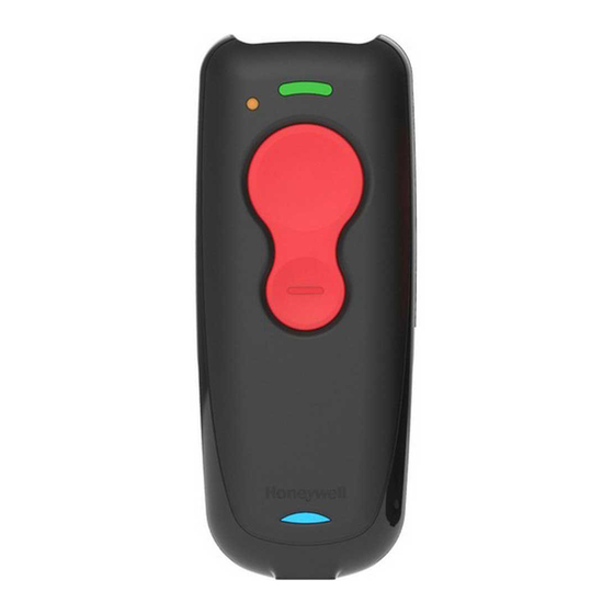
- Page 1 Voyager 1602g Wireless Area-Imaging Pocket Scanner User’s Guide The HEC and TEC codes identified in this watermark supersede any conflicting HEC or TEC codes displayed in the drawing.
- Page 2 Disclaimer Honeywell International Inc. (“HII”) reserves the right to make changes in specifications and other information contained in this document without prior notice, and the reader should in all cases consult HII to determine whether any such changes have been made.
-
Page 3: Table Of Contents
USB HID........................2-15 USB Serial........................2-15 Remote MasterMind™ for USB..................2-15 ® Gilbarco Terminal Default Settings ................2-16 Honeywell Bioptic Aux Port Configuration..............2-16 ® Datalogic™ Magellan Aux Port Configuration............2-16 NCR Bioptic Aux Port Configuration ................2-17 Wincor Nixdorf Terminal Default Settings ..............2-17 Wincor Nixdorf Beetle™ Terminal Default Settings .............2-17 Wincor Nixdorf RS232 Mode A ..................2-18... - Page 4 Programming the VG1602 Corded Interface ..............2-23 Setting the VG1602 Corded Interface................2-23 Corded USB PC or Macintosh Keyboard..............2-23 Corded USB HID POS....................2-23 Corded USB Serial ...................... 2-24 Chapter 3 - Wireless System Operation Bluetooth Settings ....................... 3-1 Bluetooth HID Keyboard Disconnect ................
- Page 5 Resetting the Factory Defaults: All Application Work Groups ........... 3-13 Resetting the Custom Defaults: All Application Work Groups ........... 3-13 Access Point Operations ....................3-13 Linking the Scanner to an Access Point ..............3-13 Disconnect from Host and Connect to an Access Point ..........3-14 Replacing a Linked Scanner..................
- Page 6 Poor Quality Codes ......................4-8 Poor Quality 1D Codes ....................4-8 Poor Quality PDF Codes ....................4-9 ® CodeGate .......................... 4-9 Mobile Phone Read Mode ....................4-9 Character Activation Mode ....................4-10 Activation Character ....................4-10 End Character Activation After Good Read ..............4-10 Character Activation Timeout ..................
- Page 7 Chapter 6 - Data Formatting Data Format Editor Introduction ..................6-1 Add a Data Format ......................6-1 Other Programming Selections..................6-2 Terminal ID Table ........................ 6-3 Data Format Editor Commands................... 6-3 Move Commands......................6-5 Search Commands ......................6-6 Miscellaneous Commands..................... 6-7 Data Formatter ........................
- Page 8 GS1 DataBar Limited......................7-31 GS1 DataBar Expanded ....................7-32 Trioptic Code ........................7-32 Codablock A ........................7-33 Codablock F ........................7-34 Label Code ........................7-34 PDF417 ..........................7-35 MacroPDF417 ........................7-35 MicroPDF417........................7-36 GS1 Composite Codes...................... 7-36 UPC/EAN Version......................7-37 GS1 Emulation ........................
- Page 9 Resetting the Custom Defaults.................... 9-3 Menu Commands ........................ 9-4 Chapter 10 - Product Specifications Voyager 1602g Wireless Pocket Scanner Product Specifications ........10-1 Standard Connector Pinout ....................10-3 Micro-B USB ........................ 10-3 Chapter 11 - Maintenance and Troubleshooting Repairs ..........................11-1 Maintenance ........................
- Page 10 viii The HEC and TEC codes identified in this watermark supersede any conflicting HEC or TEC codes displayed in the drawing.
-
Page 11: Customer Support
For our latest contact information, see www.honeywellaidc.com/locations. Product Service and Repair Honeywell International Inc. provides service for all of its products through service centers throughout the world. To obtain warranty or non-warranty service, please visit www.honeywellaidc.com and select Support > Contact Service and Repair to see your region's instructions on how to obtain a Return Material Authorization number (RMA #). - Page 12 The HEC and TEC codes identified in this watermark supersede any conflicting HEC or TEC codes displayed in the drawing.
-
Page 13: Chapter 1 - Getting Started
1602g2D and cannot be read by model 1602g1D. Honeywell bar code scanners are factory programmed for the most common terminal and communications settings. If you need to change these settings, programming is accomplished by scanning the bar codes in this guide. -
Page 14: Charging With A Pc
Scan LED Sequences and Meaning (page 3-6) and Low Battery Indicator (page 3-6) for the complete list of LED indications. To use your scanner with a Honeywell Access Point (AP01-XXXBT), refer to Host ACK Responses, page 3-22 or Linking the Scanner to an Access Point, page 3-13. -
Page 15: Pairing The Scanner With Bluetooth ® Devices
Pairing the Scanner with Bluetooth Devices ® The scanner can be paired with Bluetooth devices such as personal computers, laptops, tablets, and Apple® devices. 1. Scan the appropriate Bluetooth Connect bar code below to establish one-way communication with the Voyager 1602g. Bluetooth HID Keyboard Connect Bluetooth HID Japanese... -
Page 16: Pairing The Scanner With An Apple Device Using Spp
Save Your personal computer, laptop, tablet, or Apple device should now be paired with the scanner. Once the scanner battery is charged and you have paired it, you may begin scanning bar codes. Verify the scanner operation by scanning a bar code from the Sample Symbols in the back of this manual. -
Page 17: Reading Techniques
Menu Bar Code Security Settings Honeywell scanners are programmed by scanning menu bar codes or by sending serial commands to the scanner. If you want to restrict the ability to scan menu codes, you can use the Menu Bar Code Security settings. Contact the nearest technical sup-... -
Page 18: Setting Custom Defaults
Setting Custom Defaults You have the ability to create a set of menu commands as your own, custom defaults. To do so, scan the Set Custom Defaults bar code below before scanning the menu commands for your custom defaults. If a menu command requires scanning numeric codes from the back cover, then a Save code, that entire sequence will be saved to your custom defaults. -
Page 19: Chapter 2 - Programming The Interface
Programming the Interface Introduction This chapter describes how to program your scanner for different keyboards and settings, and for an interface when using an Access Point (see Programming an Interface for an Access Point, beginning on page 2-12). The VG1602g is primarily designed as a cordless scanner. - Page 20 Keyboard Countries (Continued) Brazil (MS) Bulgaria (Cyrillic) Bulgaria (Latin) Canada (French legacy) Canada (French) Canada (Multilingual) Croatia Czech Czech (Programmers) Czech (QWERTY) Czech (QWERTZ) 2 - 2 The HEC and TEC codes identified in this watermark supersede any conflicting HEC or TEC codes displayed in the drawing.
- Page 21 Keyboard Countries (Continued) Denmark Dutch (Netherlands) Estonia Faroese Finland France Gaelic Germany Greek Greek (220 Latin) Greek (220) 2 - 3 The HEC and TEC codes identified in this watermark supersede any conflicting HEC or TEC codes displayed in the drawing.
- Page 22 Keyboard Countries (Continued) Greek (319 Latin) Greek (319) Greek (Latin) Greek (MS) Greek (Polytonic) Hebrew Hungarian (101 key) Hungary Iceland Irish Italian (142) 2 - 4 The HEC and TEC codes identified in this watermark supersede any conflicting HEC or TEC codes displayed in the drawing.
- Page 23 Keyboard Countries (Continued) Italy Japan ASCII Kazakh Kyrgyz (Cyrillic) Latin America Latvia Latvia (QWERTY) Lithuania Lithuania (IBM) Macedonia Malta 2 - 5 The HEC and TEC codes identified in this watermark supersede any conflicting HEC or TEC codes displayed in the drawing.
- Page 24 Keyboard Countries (Continued) Mongolian (Cyrillic) Norway Poland Polish (214) Polish (Programmers) Portugal Romania Russia Russian (MS) Russian (Typewriter) 2 - 6 The HEC and TEC codes identified in this watermark supersede any conflicting HEC or TEC codes displayed in the drawing.
- Page 25 Keyboard Countries (Continued) Serbia (Cyrillic) Serbia (Latin) Slovakia Slovakia (QWERTY) Slovakia (QWERTZ) Slovenia Spain Spanish variation Sweden Switzerland (French) Switzerland (German) 2 - 7 The HEC and TEC codes identified in this watermark supersede any conflicting HEC or TEC codes displayed in the drawing.
-
Page 26: Keyboard Style
Keyboard Countries (Continued) Tatar Turkey F Turkey Q Ukrainian United Kingdom United States (Dvorak) United States (Dvorak left) United Stated (Dvorak right) United States (International) Uzbek (Cyrillic) Keyboard Style This programs keyboard styles, such as Caps Lock and Shift Lock. If you have used Keyboard Conversion settings, they will override any of the following Keyboard Style settings. -
Page 27: Keyboard Conversion
Regular is used when you normally have the Caps Lock key off. * Regular Caps Lock is used when you normally have the Caps Lock key on. Caps Lock Shift Lock is used when you normally have the Shift Lock key on (not common to U.S. keyboards). Shift Lock Automatic Caps Lock is used if you change the Caps Lock key on and off. -
Page 28: Control Character Output
Default = Keyboard Conversion Off. * Keyboard Conversion Off Convert All Characters to Upper Case Convert All Characters to Lower Case Control Character Output This selection sends a text string instead of a control character. For example, when the control character for a carriage return is expected, the output would display [CR] instead of the ASCII code of 0D. - Page 29 * Control + X Mode Off DOS Mode Control + X Mode On Windows Mode Prefix/Suffix Off Turbo Mode: The scanner sends characters to a terminal faster. If the terminal drops characters, do not use Turbo Mode. Default = Off. Turbo Mode On * Turbo Mode Off Numeric Keypad Mode: Sends numeric characters as if entered from a numeric keypad.
-
Page 30: Programming An Interface For An Access Point
Programming an Interface for an Access Point If you are using a Honeywell Access Point (AP01-XXXBT) to communicate with the VG1602, you can use the following bar codes to program the Access Point interface. These bar codes set the Access Point for commonly used interfaces. -
Page 31: Rs485
RS485 Scan one of the following “Plug and Play” codes to program the scanner for an IBM POS terminal interface. This interface is only appropriate for an Access Point. Note: After scanning one of these codes, you must power cycle the cash register. IBM Port 5B Interface IBM Port 9B HHBCR-1 Interface... -
Page 32: Usb Ibm Surepos
RS485 Packet Length If you are using Packet mode, you can specify the size of the data “packet” that is sent to the host. Scan the Packet Length bar code, then then the packet size (from 20 - 256) from the Programming Chart inside the back cover of this manual, then Save. -
Page 33: Usb Hid
RS232-based COM Port, then power cycle the host. If you are using a Microsoft® Windows® PC, you will need to down- load a driver from the Honeywell website (www.honeywellaidc.com). The driver will use the next available COM Port num- ber. Apple® Macintosh computers recognize the scanner as a USB CDC class device and automatically use a class driver. -
Page 34: Gilbarco ® Terminal Default Settings
This interface is only appropriate for an Access Point. Scan the following Plug and Play code to program the scanner for a Honeywell bioptic scanner auxiliary port configuration, then power cycle the host. This bar code sets the baud rate to 38400 bps and the data format to 8 data bits, no parity, 1 stop bit. -
Page 35: Ncr Bioptic Aux Port Configuration
NCR Bioptic Aux Port Configuration This interface is only appropriate for an Access Point. Scan the following Plug and Play code to program the scanner for an NCR bioptic scanner auxiliary port configuration, then power cycle the host. The following prefixes are programmed for each symbology: Symbology Prefix... -
Page 36: Wincor Nixdorf Rs232 Mode A
Wincor Nixdorf RS232 Mode A This interface is only appropriate for an Access Point. Scan the following Plug and Play code to program the scanner for a Wincor Nixdorf RS232 Mode A terminal, then power cycle the host. This bar code sets the baud rate to 9600 bps and the data format to 8 data bits, odd parity, 1 stop bit. - Page 37 38400 57,600 * 115,200 RS232 Word Length: Data Bits, Stop Bits, and Parity Data Bits sets the word length at 7 or 8 bits of data per character. If an application requires only ASCII Hex characters 0 through 7F decimal (text, digits, and punctuation), select 7 data bits. For applications that require use of the full ASCII set, select 8 data bits per character.
- Page 38 * 8 Data, 1 Stop, Parity None 8 Data, 1 Stop, Parity Odd 8 Data, 1 Stop, Parity Mark RS232 Receiver Time-Out The unit stays awake to receive data until the RS232 Receiver Time-Out expires. A scan button push or serial trigger command resets the time-out.
- Page 39 * RTS/CTS Off RS232 Timeout When using Flow Control with Timeout, you must program the length of the delay you want to wait for CTS from the host. Set the length (in milliseconds) for a timeout by scanning the bar code below, then setting the timeout (from 1- 5100 milliseconds) by scanning digits from the inside back cover, then scanning Save.
-
Page 40: Scanner To Bioptic Communication
The following Scanner to Bioptic Communication settings should only be used when connecting through an Access Point. They are used to set up communication between Honeywell scanners and bioptic scanners. Note: The scanner’s baud rate must be set to 38400 and the RS232 timeout must be set to 3000 in order to communicate with a bioptic scanner. -
Page 41: Programming The Vg1602 Corded Interface
Programming the VG1602 Corded Interface You may convert a VG1602 scanner to a corded scanner using a USB interface cable. Use the following bar codes to program the VG1602g as a corded scanner. Setting the VG1602 Corded Interface Scan one of the following codes to set the scanner’s communication as either Bluetooth, for a cordless scanner, to USB, for a corded scanner. -
Page 42: Corded Usb Serial
Scan the following code to program the corded scanner to emulate a regular RS232-based COM Port, then power cycle the host. If you are using a Microsoft® Windows® PC, you will need to download a driver from the Honeywell website (www.honeywellaidc.com). -
Page 43: Chapter 3 - Wireless System Operation
Non-Base BT Connection PDAs/Mobility Systems Devices You may also use the scanner with a PDA or a Honeywell Mobility Systems device. Scan the bar code below and follow the instructions supplied with your Bluetooth device to locate and pair with the scanner. -
Page 44: Minimizing Bluetooth/Ism Band Network Activity
Minimizing Bluetooth/ISM Band Network Activity The settings described below can help you customize the relinking behavior of the wireless area-imaging system to obtain the best compromise between convenience and low interference. Note: ISM band refers to the 2.4 to 2.48 GHz frequency band used by wireless networks, cordless phones, and Bluetooth. Auto Reconnect Mode Auto Reconnect controls whether or not the scanner automatically begins the relink process when a loss of connection is detected. -
Page 45: Relink Time-Out
Scan the Maximum Link Attempts bar code, then scan the number of attempts for the setting (from 0-100) from the inside back cover. Scan Save to save the setting. Default = 0. Maximum Link Attempts Note: When Auto Reconnect Mode is On, setting Maximum Link Attempts to zero will cause the scanner to try to link until the Power Time-Out Timer setting (see page 3-9) expires. -
Page 46: Communication Between The Scanner And The Host
The scanner attempts to connect to the host every 15 seconds, measured from one attempt start to the next attempt start. After one half hour, the scanner powers off. Communication Between the Scanner and the Host When data is scanned, the data is sent to the host system. The wireless scanner provides immediate feedback in the form of a “good read”... -
Page 47: Charging Information
• Although your battery can be recharged many times, it will eventually be depleted. Replace it after the battery is unable to hold an adequate charge. • If you are not sure if the battery or charger is working properly, send it to Honeywell International Inc. or an authorized service center for inspection. Refer to Customer Support on page -ix for additional information. -
Page 48: Scan Led Sequences And Meaning
Scan LED Sequences and Meaning LED Indication Beeper Indication Cause Normal Operation Red flash None Battery low Green flash 1 beep Successful scan Red, blinking Razz or error tone Failed communication Blue, off None Bluetooth connection has not been established Blue flash None Scanner is attempting to pair with... -
Page 49: Scanner Address
Scanner Address Scan the bar code below to determine the address of the scanner you are using. Scanner Address Linked Modes Locked Link Mode and Open Link Mode are the link modes that accommodate different applications. Scan the appropriate bar codes included in the Open Link and Locked Link Mode explanations that follow to switch from one mode to another. -
Page 50: Override Locked Scanner
Override Locked Scanner (Single Scanner) Out-of-Range Alarm Note: This feature is only supported by a Honeywell Access Point (AP). See Access Point Operations, beginning on page 3-13 for further information. -
Page 51: Scanner Idle Alarm
Scanner Idle Alarm When the scanner is idle for over 1 hour, you can set it to beep every minute until the trigger is pressed. Default = Scanner Idle Alarm Off. Scanner Idle Alarm On * Scanner Idle Alarm Off Scanner Power Time-Out Timer When there is no activity within a specified time period, the scanner enters low power mode. -
Page 52: Flexible Power Management
Note: When the scanner is in power down mode, press the scan button to power the unit back up. There will be a set of power up beeps and a delay of up to a few seconds for the radio to join. The scanner will then be ready to use. Flexible Power Management If you are experiencing network performance issues, and suspect the scanner is interfering with other devices, you can turn down the power output of the scanner. - Page 53 The default name is in the format “ScannerName_Model_SN_XXXXXXXXXX” If you have more than one scanner linked to a host and they all have the same name, the first scanner linked to the host receives commands. When renaming a series of scanners with identical names, unlink all except one of the scanners from the host.
-
Page 54: Application Work Groups
You could assign all the scanners in the retail area to one work group and those in the warehouse to another. Consequently, any desired changes to either the retail or warehouse area would apply to all scanners in that particular work group. Honeywell’s online configuration tool, EZConfig-Scanning (page 8-2), makes it easy for you to program your system for use with multiple scanners and multiple work groups. -
Page 55: Resetting The Factory Defaults: All Application Work Groups
Access Point Operations The Voyager 1602g can pair with a Honeywell Access Point (AP01-010BT or AP01-100BT), which provides 2-way communica- tion between the scanner and host. Linking the Scanner to an Access Point Turn on the host computer (laptop/desktop). -
Page 56: Disconnect From Host And Connect To An Access Point
Scan the linking bar code on the top of the Access Point to establish a connection between the Access Point and the scan- ner. The scanner emits a short beep and flashes the green LED to confirm a connection with the Access Point. The Access Point’s Page button remains blue. -
Page 57: Access Point Led Sequences And Meaning
Access Point LED Sequences and Meaning The Access Point has a blue LED on the top of the unit that indicates its power up and communication condition. Blue LED - Host Communication Blue LED Communication Condition USB suspend On continuously Power on, system idle Short blinks in multiple pulses. -
Page 58: Batch Mode
High (4200 Hz) Batch Mode Batch mode is used to store bar code data when a scanner is out of range of its host, or when performing inventory. The scan- ner may store a number of symbols (approximately 500 U.P.C. symbols; others may vary) when it is out of range and then send them to the host when back in range or when the records are manually transmitted. -
Page 59: Batch Mode Beep
Batch Mode Beep When scanning in Inventory Batch Mode (page 3-16), the scanner beeps every time a bar code is scanned. When Batch Mode Beep is On, you will also hear a click when each bar code is sent to the host. If you do not want to hear these clicks, scan Batch Mode Beep Off. - Page 60 Batch Mode Quantity On Entering Quantities Quantity Codes (page 3-19) allow you to enter a quantity for the last item scanned, up to 9999 (default = 1). Quantity digits are shifted from right to left, so if a 5th digit is scanned, the 1st digit scanned is discarded and the 2nd, 3rd and 4th digits are moved to the left to accommodate the new digit.
-
Page 61: Batch Mode Output Order
Batch Mode Output Order When batch data is transmitted, select whether you want that data sent as FIFO (first-in first-out), or LIFO (last-in first-out). Default = Batch Mode FIFO. * Batch Mode FIFO Batch Mode LIFO Total Records If you wish to output the total number of bar codes scanned when in Batch Mode, scan Total Records. Total Records 3 - 19 The HEC and TEC codes identified in this watermark supersede any conflicting HEC or TEC codes displayed in the drawing. -
Page 62: Delete Last Code
Delete Last Code If you want to delete the last bar code scanned when in Batch Mode, scan Delete Last Code. Delete Last Code Clear All Codes If you want to clear the scanner’s buffer of all data accumulated in Batch Mode, scan Clear All Codes. Clear All Codes Transmit Records to Host If you are operating in Inventory Batch Mode (see... -
Page 63: Host Acknowledgment
The following criteria must be met for the Host ACK to work correctly: • The scanner must be paired with a Honeywell Access Point (AP01-010BT or AP01-100BT). • The wireless system must be configured for Host Port RS232 (terminal ID = 000) or USB COM Emulation (terminal ID = 130). -
Page 64: Host Ack Timeout
Host ACK On/Off Host ACK On * Host ACK Off Host ACK Timeout You can set a timeout for the length of time the scanner waits for a valid escape command when using Host Acknowledg- ment Mode. Set the length (in seconds) for a timeout by scanning the following bar code, then setting the timeout (from 1- 90 seconds) by scanning digits from the Programming Chart inside the back cover of this manual, then scanning Save. -
Page 65: Chapter 4 - Input/Output Settings
Input/Output Settings Programmable Button The second, smaller button on the scanner can be programmed so that pressing the button displays a virtual keyboard on the host, displays the battery charge status, puts the scanner into flashlight mode, or pairs and unpairs the Bluetooth connection between the scanner and the host. -
Page 66: Battery Charge Status
Battery Charge Status If you want the battery indicator LED to flash in a pattern that indicates the battery charge level, scan one of the following bar codes. Battery Charge Status On - Short Press Battery Charge Status On - Long Press The battery LED flashes in the following patterns after a short or long press of the programmable button: Battery LED... -
Page 67: Bluetooth Pair/Unpair
Bluetooth Pair/Unpair The programmable button can be used to toggle between pairing and unpairing from the host. Scan one of the following bar codes to set the Bluetooth Pair/Unpair with a short or long press of the programmable button: Bluetooth Pair/Unpair On - Short Press Bluetooth Pair/Unpair On - Long Press... -
Page 68: Power Up Beeper
Power Up Beeper The scanner can be programmed to beep when it’s powered up. Scan the Off bar code(s) if you don’t want a power up beep. Default = Power Up Beeper On. Power Up Beeper Off * Power Up Beeper On Beep on BEL Character You may wish to force the scanner to beep upon a command sent from the host. -
Page 69: Good Read And Error Indicators
Good Read and Error Indicators Beeper – Good Read The beeper may be programmed On or Off in response to a good read. Turning this option off only turns off the beeper response to a good read indication. All error and menu beeps are still audible. Default = Beeper - Good Read On. Beeper - Good Read Off * Beeper - Good Read On Beeper Volume –... -
Page 70: Beeper Pitch - Error
High (4200 Hz) Beeper Pitch – Error The beeper pitch codes modify the pitch (frequency) of the sound the scanner emits when there is a bad read or error. Default = Razz. * Razz (250 Hz) Medium (3250 Hz) High (4200 Hz) Beeper Duration –... -
Page 71: Number Of Beeps - Good Read
Number of Beeps – Good Read The number of beeps of a good read can be programmed from 1 - 9. The same number of beeps will be applied to the beeper and LED in response to a good read. For example, if you program this option to have five beeps, there will be five beeps and five LED flashes in response to a good read. -
Page 72: Manual Trigger Modes
Manual Trigger Modes When in manual trigger mode, the scanner scans until a bar code is read or until the scan button is released. Two modes are available, Normal and Enhanced. Normal mode offers good scan speed and the longest working ranges (depth of field). Enhanced mode will give you the highest possible scan speed but slightly less range than Normal mode. -
Page 73: Poor Quality Pdf Codes
Poor Quality PDF Codes This setting improves the scanner’s ability to read damaged or badly printed PDF codes by combining information from mul- tiple images. When Poor Quality PDF On is scanned, poor quality PDF code reading is improved, but the scanner’s snap- piness is decreased, making it less aggressive when reading good quality bar codes. -
Page 74: Character Activation Mode
Character Activation Mode You may use a character sent from the host to trigger the scanner to begin scanning. When the activation character is received, the scanner continues scanning until either the Character Activation Timeout (page 4-11), the deactivation character is received (see Deactivation Character on page 4-11), or a bar code is transmitted. -
Page 75: Character Activation Timeout
Character Activation Timeout You can set a timeout for the length of time the illumination remains on and attempting to decode bar codes when using Character Activation Mode. Set the length (in milliseconds) for a timeout by scanning the following bar code, then setting the timeout (from 1-300,000 milliseconds) by scanning digits from the Programming Chart inside the back cover of this... -
Page 76: Aimer Delay
Aimer Delay The aimer delay allows a delay time for the operator to aim the scanner before the bar code is read. Use these codes to set the time between when the button is pressed and when the bar code is read. During the delay time, the aiming light will appear, but the LEDs won’t turn on until the delay time is over. - Page 77 In the example below, the white box is the centering window. The centering window has been set to 20% left, 30% right, 8% top, and 25% bottom. Since Bar Code 1 passes through the centering window, it will be read. Bar Code 2 does not pass through the centering window, so it will not be read.
-
Page 78: Preferred Symbology
Right of Centering Window Preferred Symbology The scanner can be programmed to specify one symbology as a higher priority over other symbologies in situations where both bar code symbologies appear on the same label, but the lower priority symbology cannot be disabled. For example, you may be using the scanner in a retail setting to read U.P.C. -
Page 79: Preferred Symbology Time-Out
If you want to set additional low priority symbologies, scan FF, then scan the 2 digit hex value from the Programming Chart for the next symbology. You can program up to 5 low priority symbologies. Scan Save to save your selection. Default = None. -
Page 80: Other Programming Selections
5. End Output Sequence Editor Scan F F to enter an Output Sequence for an additional symbology, or Save to save your entries. Other Programming Selections • Discard This exits without saving any Output Sequence changes. Output Sequence Example In this example, you are scanning Code 93, Code 128, and Code 39 bar codes, but you want the scanner to output Code 39 1st, Code 128 2nd, and Code 93 3rd, as shown below. -
Page 81: Output Sequence Editor
start character match for Code 39, 41h = “A” termination string for first code code identifier for Code 128 0013 B - Code 128 sample length (12) plus CR suffix (1) = 13 start character match for Code 128, 42h = “B” termination string for second code code identifier for Code 93 0012... -
Page 82: Multiple Symbols
When the output sequence is Off, the bar code data is output to the host as the scanner decodes it. Default = Off. Note: This selection is unavailable when the Multiple Symbols Selection is turned on. Required On/Not Required *Off Multiple Symbols When this programming selection is turned On, it allows you to read multiple symbols with a single press of the scanner’s but- ton. -
Page 83: Video Reverse
Video Reverse Video Reverse is used to allow the scanner to read bar codes that are inverted. The Video Reverse Off bar code below is an example of this type of bar code. Scan Video Reverse Only to read only inverted bar codes. Scan Video Reverse and Stan- dard Bar Codes to read both types of codes. - Page 84 * Upright Vertical, Bottom to Top Upside Down Vertical, Top to Bottom 4 - 20 The HEC and TEC codes identified in this watermark supersede any conflicting HEC or TEC codes displayed in the drawing.
-
Page 85: Chapter 5 - Data Editing
Data Editing Prefix/Suffix Overview When a bar code is scanned, additional information is sent to the host computer along with the bar code data. This group of bar code data and additional, user-defined data is called a “message string.” The selections in this section are used to build the user-defined data into the message string. -
Page 86: To Clear One Or All Prefixes Or Suffixes
Example: Add a Tab Suffix to All Symbologies Step 1. Scan Add Suffix. Step 2. Scan 9, 9 from the Programming Chart inside the back cover of this manual to apply this suffix to all symbologies. Step 3. Scan 0, 9 from the Programming Chart inside the back cover of this manual. -
Page 87: Function Code Transmit
Clear One Suffix Clear All Suffixes Function Code Transmit When this selection is enabled and function codes are contained within the scanned data, the scanner transmits the function code to the terminal. Charts of these function codes are provided in ASCII Conversion Chart (Code Page 1252) starting on page... -
Page 88: Interfunction Delay
Next, scan the Character to Trigger Delay bar code, tthen the 2-digit hex value for a printable character to trigger the delay (see Lower ASCII Reference Table on page A-4). Delay Length Character to Trigger Delay To remove this delay, scan the Delay Length bar code, and set the number of delays to 0. Scan the Save bar code using Programming Chart inside the back cover of this manual. -
Page 89: Data Format Editor Introduction
Data Formatting Data Format Editor Introduction You may use the Data Format Editor to change the scanner’s output. For example, you can use the Data Format Editor to insert characters at certain points in bar code data as it is scanned. The selections in the following pages are used only if you wish to alter the output. -
Page 90: Other Programming Selections
Step 5. Length Specify what length (up to 9999 characters) of data will be acceptable for this symbology. Scan the four digit data length from the Programming Chart inside the back cover of this manual. For example, 50 characters is entered as 0050. Note: 9999 indicates all lengths. -
Page 91: Terminal Id Table
Terminal ID Table Terminal Model(s) Terminal ID PC keyboard (HID) Mac Keyboard PC Keyboard (Japanese) Serial (COM driver required) HID POS USB SurePOS Handheld USB SurePOS Tabletop Serial RS232 TTL RS232 True RS485 (IBM-HHBCR 1+2, 46xx) Keyboard PS2 compatibles AT compatibles Data Format Editor Commands When working with the Data Format Editor, a virtual cursor is moved along your input data string. -
Page 92
F1 is the “Send all characters” command 0D is the hex value for a CR The data is output as: 1234567890 ABCDEFGHIJ
Send all characters up to a particular character F3 Include in the output message all characters from the input message, starting with the character at the current cursor position and continuing to, but not including, the search character “ss,”... -
Page 93: Move Commands
Move Commands Move the cursor forward a number of characters F5 Move the cursor ahead “nn” characters from current cursor position. Syntax = F5nn where nn is the numeric value (00-99) for the number of characters the cursor should be moved ahead. F5 Example: Move the cursor forward and send the data Move the cursor forward 3 characters, then send the rest of the bar code data from the bar code above. -
Page 94: Search Commands
Search Commands Search forward for a character F8 Search the input message forward for “xx” character from the current cursor position, leaving the cursor pointing to the “xx” character. Syntax = F8xx where xx stands for the search character’s hex value for its ASCII code. Refer to the ASCII Conversion Chart (Code Page 1252), beginning on page A-3 for decimal, hex and character codes. -
Page 95: Miscellaneous Commands
Miscellaneous Commands Suppress characters FB Suppress all occurrences of up to 15 different characters, starting at the current cursor position, as the cursor is advanced by other commands. When the FC command is encountered, the suppress function is terminated. The cursor is not moved by the FB command. -
Page 96
The data is output as: 1234 5678
Stop replacing characters E5 Terminates character replacement. Syntax = E5. Compare characters FE Compare the character in the current cursor position to the character “xx.” If characters are equal, move the cursor forward one position. -
Page 97: Data Formatter
Insert a delay EF Inserts a delay of up to 49,995 milliseconds (in multiples of 5), starting from the current cursor position. Syntax = EFnnnn where nnnn stands for the delay in 5ms increments, up to 9999. This command can only be used with keyboard emulation. -
Page 98: Data Format Non-Match Error Tone
Data Format Non-Match Error Tone When a bar code is encountered that doesn’t match your required data format, the scanner normally generates an error tone. However, you may want to continue scanning bar codes without hearing the error tone. If you scan the Data Format Non-Match Error Tone Off bar code, data that doesn’t conform to your data format is not transmitted, and no error tone will sound. - Page 99 For example, you may have set your device to the data format you saved as Data Format 3. You can switch to Data Format 1 for a single button press by scanning the Single Scan-Data Format 1 bar code below. The next bar code that is scanned uses Data Format 1, then reverts back to Data Format 3.
- Page 100 6 - 12 The HEC and TEC codes identified in this watermark supersede any conflicting HEC or TEC codes displayed in the drawing.
-
Page 101: All Symbologies
Symbologies This programming section contains the following menu selections. Refer to Chapter 9 for settings and defaults. • All Symbologies • Interleaved 2 of 5 • Aztec Code • Korea Post • China Post (Hong Kong 2 of 5) • Matrix 2 of 5 •... -
Page 102: Message Length Description
Message Length Description You are able to set the valid reading length of some of the bar code symbologies. You may wish to set the same value for min- imum and maximum length to force the scanner to read fixed length bar code data. This helps reduce the chances of a misread. EXAMPLE: Decode only those bar codes with a count of 9-20 characters. -
Page 103: Codabar Concatenation
When Check Character is set to Validate, but Don’t Transmit, the unit will only read Codabar bar codes printed with a check character, but will not transmit the check character with the scanned data. * No Check Character Validate Modulo 16, but Don’t Transmit Validate Modulo 16 and Transmit... -
Page 104: Code 39
Maximum Message Length Code 39 < Default All Code 39 Settings > Code 39 On/Off * On Code 39 Start/Stop Characters Start/Stop characters identify the leading and trailing ends of the bar code. You may either transmit, or not transmit Start/ Stop characters. -
Page 105: Code 32 Pharmaceutical (Paraf)
Validate, but Don’t Transmit Validate and Transmit Code 39 Message Length Scan the bar codes below to change the message length. Refer to Message Length Description (page 7-2) for additional information. Minimum and Maximum lengths = 0-48. Minimum Default = 0, Maximum Default = 48. Minimum Message Length Maximum Message Length Code 39 Append... -
Page 106: Full Ascii
Full ASCII If Full ASCII Code 39 decoding is enabled, certain character pairs within the bar code symbol will be interpreted as a single character. For example: $V will be decoded as the ASCII character SYN, and /C will be decoded as the ASCII character #. Default = Off. -
Page 107: Interleaved 2 Of 5
Interleaved 2 of 5 < Default All Interleaved 2 of 5 Settings > Interleaved 2 of 5 On/Off * On Check Digit No Check Digit indicates that the scanner reads and transmits bar code data with or without a check digit. When Check Digit is set to Validate, but Don’t Transmit, the unit only reads Interleaved 2 of 5 bar codes printed with a check digit, but will not transmit the check digit with the scanned data. -
Page 108: Nec 2 Of 5
Maximum Message Length NEC 2 of 5 < Default All NEC 2 of 5 Settings > NEC 2 of 5 On/Off * On Check Digit No Check Digit indicates that the scanner reads and transmits bar code data with or without a check digit. When Check Digit is set to Validate, but Don’t Transmit, the unit only reads NEC 2 of 5 bar codes printed with a check digit, but will not transmit the check digit with the scanned data. -
Page 109: Code 93
NEC 2 of 5 Message Length Scan the bar codes below to change the message length. Refer to Message Length Description (page 7-2) for additional information. Minimum and Maximum lengths = 2-80. Minimum Default = 4, Maximum Default = 80. Minimum Message Length Maximum Message Length Code 93... -
Page 110: Code 93 Code Page
Code 93 Append This function allows the scanner to append the data from several Code 93 bar codes together before transmitting them to the host computer. When this function is enabled, the scanner stores those Code 93 bar codes that start with a space (excluding the start and stop symbols), and does not immediately transmit the data. -
Page 111: Straight 2 Of 5 Industrial (Three-Bar Start/Stop)
Straight 2 of 5 Industrial (three-bar start/stop)Straight 2 of 5 Industrial On/Off * Off Straight 2 of 5 Industrial Message Length Scan the bar codes below to change the message length. Refer to Message Length Description (page 7-2) for additional information. -
Page 112: Straight 2 Of 5 Iata (Two-Bar Start/Stop)
Straight 2 of 5 IATA (two-bar start/stop)Straight 2 of 5 IATA On/Off * Off Straight 2 of 5 IATA Message Length Scan the bar codes below to change the message length. Refer to Message Length Description (page 7-2) for additional information. -
Page 113: Matrix 2 Of 5
Matrix 2 of 5Matrix 2 of 5 On/Off * Off Matrix 2 of 5 Message Length Scan the bar codes below to change the message length. Refer to Message Length Description (page 7-2) for additional information. -
Page 114: Code 11
Code 11Code 11 On/Off * Off Check Digits Required This option sets whether 1 or 2 check digits are required with Code 11 bar codes. Default = Two Check Digits. One Check Digit * Two Check Digits Code 11 Message Length Scan the bar codes below to change the message length. -
Page 115: Code 128
Code 128Code 128 On/Off * On ISBT 128 Concatenation In 1994 the International Society of Blood Transfusion (ISBT) ratified a standard for communicating critical blood informa- tion in a uniform manner. The use of ISBT formats requires a paid license. The ISBT 128 Application Specification describes 1) the critical data elements for labeling blood products, 2) the current recommendation to use Code 128 due to its high degree of security and its space-efficient design, 3) a variation of Code 128 that supports concatenation of neigh- boring symbols, and 4) the standard layout for bar codes on a blood product label. -
Page 116: Code 128 Code Page
Code 128 Append This function allows the scanner to append the data from several Code 128 bar codes together before transmitting them to the host computer. When the scanner encounters a Code 128 bar code with the append trigger character(s), it buffers Code 128 bar codes until it reads a Code 128 bar code that does not have the append trigger. -
Page 117: Gs1-128
GS1-128GS1-128 On/Off * On GS1-128 Message Length Scan the bar codes below to change the message length. Refer to Message Length Description (page 7-2) for additional information. Minimum and Maximum lengths = 1-80. Minimum Default = 1, Maximum Default = 80. Minimum Message Length Maximum Message Length 7 - 17... -
Page 118: Telepen
TelepenTelepen On/Off * Off Telepen Output Using AIM Telepen Output, the scanner reads symbols with start/stop pattern 1 and decodes them as standard full ASCII (start/stop pattern 1). When Original Telepen Output is selected, the scanner reads symbols with start/stop pattern 1 and decodes them as compressed numeric with optional full ASCII (start/stop pattern 2). -
Page 119: Upc-A
UPC-AUPC-A On/Off * On Note: To convert UPC-A bar codes to EAN-13, see Convert UPC-A to EAN-13 on page 7-24. UPC-A Check Digit This selection allows you to specify whether the check digit should be transmitted at the end of the scanned data or not. Default = On. - Page 120 UPC-A Addenda This selection adds 2 or 5 digits to the end of all scanned UPC-A data. Default = Off for both 2 Digit and 5 Digit Addenda. 2 Digit Addenda On * 2 Digit Addenda Off 5 Digit Addenda On * 5 Digit Addenda Off UPC-A Addenda Required When Required is scanned, the scanner will only read UPC-A bar codes that have addenda.
-
Page 121: Upc-A/Ean-13 With Extended Coupon Code
UPC-A/EAN-13 with Extended Coupon Code Use the following codes to enable or disable UPC-A and EAN-13 with Extended Coupon Code. When left on the default setting (Off), the scanner treats Coupon Codes and Extended Coupon Codes as single bar codes. If you scan the Allow Concatenation code, when the scanner sees the coupon code and the extended coupon code in a single scan, it transmits both as one symbology. -
Page 122: Upc-E0
UPC-E0UPC-E0 On/Off Most U.P.C. bar codes lead with the 0 number system. To read these codes, use the UPC-E0 On selection. If you need to read codes that lead with the 1 number system, use UPC-E1 (page 7-24). - Page 123 UPC-E0 Addenda Separator When this feature is On, there is a space between the data from the bar code and the data from the addenda. When turned Off, there is no space. Default = On. * On UPC-E0 Check Digit Check Digit specifies whether the check digit should be transmitted at the end of the scanned data or not.
-
Page 124: Upc-E1
5 Digit Addenda On * 5 Digit Addenda Off UPC-E1 Most U.P.C. bar codes lead with the 0 number system. For these codes, use UPC-E0 (page 7-22). If you need to read codes that lead with the 1 number system, use the UPC-E1 On selection. Default = Off. UPC-E1 On * UPC-E1 Off EAN/JAN-13... - Page 125 * Do not Convert UPC-A EAN/JAN-13 Check Digit This selection allows you to specify whether the check digit should be transmitted at the end of the scanned data or not. Default = On. * On EAN/JAN-13 Addenda This selection adds 2 or 5 digits to the end of all scanned EAN/JAN-13 data. Default = Off for both 2 Digit and 5 Digit Addenda.
-
Page 126: Isbn Translate
* Not Required EAN/JAN-13 Addenda Separator When this feature is On, there is a space between the data from the bar code and the data from the addenda. When turned Off, there is no space. Default = On. * On Note: If you want to enable or disable EAN13 with Extended Coupon Code, refer to UPC-A/EAN-13 with Extended Coupon Code... -
Page 127: Ean/Jan-8
EAN/JAN-8EAN/JAN-8 On/Off * On EAN/JAN-8 Check Digit This selection allows you to specify whether the check digit should be transmitted at the end of the scanned data or not. Default = On. * On EAN/JAN-8 Addenda This selection adds 2 or 5 digits to the end of all scanned EAN/JAN-8 data. - Page 128 * 5 Digit Addenda Off EAN/JAN-8 Addenda Required When Required is scanned, the scanner will only read EAN/JAN-8 bar codes that have addenda. Default = Not Required. Required * Not Required EAN/JAN-8 Addenda Separator When this feature is On, there is a space between the data from the bar code and the data from the addenda. When turned Off, there is no space.
-
Page 129: Msi
MSI On/Off * Off MSI Check Character Different types of check characters are used with MSI bar codes. You can program the scanner to read MSI bar codes with Type 10 check characters. Default = Validate Type 10, but Don’t Transmit. When Check Character is set to Validate Type 10/11 and Transmit, the scanner will only read MSI bar codes printed with the specified type check character(s), and will transmit the character(s) at the end of the scanned data. - Page 130 Validate Type 11 then Type 10 Character and Transmit Disable MSI Check Characters MSI Message Length Scan the bar codes below to change the message length. Refer to Message Length Description (page 7-2) for additional information. Minimum and Maximum lengths = 4-48. Minimum Default = 4, Maximum Default = 48. Minimum Message Length Maximum Message Length 7 - 30...
-
Page 131: Gs1 Databar Omnidirectional
GS1 DataBar Omnidirectional < Default All GS1 DataBar Omnidirectional Settings > GS1 DataBar Omnidirectional On/Off * On GS1 DataBar Limited < Default All GS1 DataBar Limited Settings > GS1 DataBar Limited On/Off * On 7 - 31 The HEC and TEC codes identified in this watermark supersede any conflicting HEC or TEC codes displayed in the drawing. -
Page 132: Gs1 Databar Expanded
GS1 DataBar Expanded < Default All GS1 DataBar Expanded Settings > GS1 DataBar Expanded On/Off * On GS1 DataBar Expanded Message Length Scan the bar codes below to change the message length. Refer to Message Length Description (page 7-2) for additional information. -
Page 133: Codablock A
Codablock ACodablock A On/Off * Off Codablock A Message Length Scan the bar codes below to change the message length. Refer to Message Length Description (page 7-2) for additional information. Minimum and Maximum lengths = 1-600. Minimum Default = 1, Maximum Default = 600. Minimum Message Length Maximum Message Length 7 - 33... -
Page 134: Codablock F
Codablock FCodablock F On/Off * Off Codablock F Message Length Scan the bar codes below to change the message length. Refer to Message Length Description (page 7-2) for additional information. Minimum and Maximum lengths = 1-2048. Minimum Default = 1, Maximum Default = 2048. Minimum Message Length Maximum Message Length Label Code... -
Page 135: Pdf417
PDF417 < Default All PDF417 Settings > PDF417 On/Off * On PDF417 Message Length Scan the bar codes below to change the message length. Refer to Message Length Description (page 7-2) for additional information. Minimum and Maximum lengths = 1-2750. Minimum Default = 1, Maximum Default = 2750. Minimum Message Length Maximum Message Length MacroPDF417... -
Page 136: Micropdf417
MicroPDF417 < Default All MicroPDF417 Settings > MicroPDF417 On/Off * Off MicroPDF417 Message Length Scan the bar codes below to change the message length. Refer to Message Length Description (page 7-2) for additional information. Minimum and Maximum lengths = 1-366. Minimum Default = 1, Maximum Default = 366. Minimum Message Length Maximum Message Length GS1 Composite Codes... -
Page 137: Upc/Ean Version
UPC/EAN Version Scan the UPC/EAN Version On bar code to decode GS1 Composite symbols that have a U.P.C. or an EAN linear compo- nent. (This does not affect GS1 Composite symbols with a GS1-128 or GS1 linear component.) Default = UPC/EAN Ver- sion Off. -
Page 138: Tcif Linked Code 39 (Tlc39)
GS1 DataBar Emulation GS1 Code Expansion Off EAN8 to EAN13 Conversion * GS1 Emulation Off TCIF Linked Code 39 (TLC39) This code is a composite code since it has a Code 39 linear component and a MicroPDF417 stacked code component. All bar code readers are capable of reading the Code 39 linear component. -
Page 139: Qr Code Page
QR Code Message Length Scan the bar codes below to change the message length. Refer to Message Length Description (page 7-2) for additional information. Minimum and Maximum lengths = 1-7089. Minimum Default = 1, Maximum Default = 7089. Minimum Message Length Maximum Message Length QR Code Append This function allows the scanner to append the data from several QR Code bar codes together before transmitting them to... -
Page 140: Data Matrix
Data Matrix < Default All Data Matrix Settings > Data Matrix On/Off * On Data Matrix Message Length Scan the bar codes below to change the message length. Refer to Message Length Description (page 7-2) for additional information. Minimum and Maximum lengths = 1-3116. Minimum Default = 1, Maximum Default = 3116. Minimum Message Length Maximum Message Length Data Matrix Append... -
Page 141: Maxicode
codes were created (see ISO 2022/ISO 646 Character Replacements on page A-7), and scan the value and the Save bar code from the Programming Chart on the inside the back cover of this manual. The data characters should then appear properly. -
Page 142: Aztec Code
Aztec Code < Default All Aztec Code Settings > Aztec Code On/Off * On Aztec Code Message Length Scan the bar codes below to change the message length. Refer to Message Length Description (page 7-2) for additional information. Minimum and Maximum lengths = 1-3832. Minimum Default = 1, Maximum Default = 3832. Minimum Message Length Maximum Message Length Aztec Append... -
Page 143: Chinese Sensible (Han Xin) Code
codes were created (see ISO 2022/ISO 646 Character Replacements on page A-7), and scan the value and the Save bar code from the Programming Chart on the inside the back cover of this manual. The data characters should then appear properly. -
Page 144: Postal Codes - 2D
Postal Codes - 2D The following lists the possible 2D postal codes, and 2D postal code combinations that are allowed. Only one 2D postal code selection can be active at a time. If you scan a second 2D postal code selection, the first selection is overwritten. Default = 2D Postal Codes Off. -
Page 145: Combination 2D Postal Codes
Postnet On Also see Postnet Check Digit, page 7-47. Postnet with B and B’ Fields On InfoMail On Combination 2D Postal Codes: InfoMail and British Post On Intelligent Mail Bar Code and Postnet with B and B’ Fields On Postnet and Postal-4i On Postnet and Intelligent Mail Bar Code On... - Page 146 Planet Code and Postnet with B and B’ Fields On Planet Code and Postal-4i On Planet Code and Intelligent Mail Bar Code On Planet Code, Postnet, and Postal-4i On Planet Code, Postnet, and Intelligent Mail Bar Code On Planet Code, Postal-4i, and Intelligent Mail Bar Code On Postnet,...
- Page 147 Planet Code, Postal-4i, Intelligent Mail Bar Code, and Postnet On Planet Code, Postal-4i, Intelligent Mail Bar Code, and Postnet with B and B’ Fields On Planet Code Check Digit This selection allows you to specify whether the check digit should be transmitted at the end of Planet Code data. Default = Don’t Transmit.
-
Page 148: Postal Codes - Linear
Combination C and N Tables causes the field to be interpreted using either the C or N Tables. * Bar Output Numeric N Table Alphanumeric C Table Combination C and N Tables Postal Codes - Linear The following lists linear postal codes. Any combination of linear postal code selections can be active at a time. China Post (Hong Kong 2 of 5)... -
Page 149: Korea Post
Maximum Message Length Korea PostKorea Post * Off Korea Post Message Length Scan the bar codes below to change the message length. Refer to Message Length Description (page 7-2) for addi- tional information. Minimum and Maximum lengths = 2-80. Minimum Default = 4, Maximum Default = 48. Minimum Message Length Maximum Message Length Korea Post Check Digit... - Page 150 7 - 50 The HEC and TEC codes identified in this watermark supersede any conflicting HEC or TEC codes displayed in the drawing.
-
Page 151: Chapter 8 - Utilities
Utilities To Add a Test Code I.D. Prefix to All Symbologies This selection allows you to turn on transmission of a Code I.D. before the decoded symbology. (See the Symbology Charts, beginning on page A-1) for the single character code that identifies each symbology.) This action first clears all current prefixes, then programs a Code I.D. -
Page 152: Test Menu
Test Menu When you scan the Test Menu On code, then scan a programming code in this manual, the scanner displays the content of a programming code. The programming function will still occur, but in addition, the content of that programming code is output to the terminal. -
Page 153: Ezconfig-Scanning Introduction
7. Using Explorer, go to the c:\windows\temp file. 8. Double click on the Setup.exe file. Follow the screen prompts to install the EZConfig-Scanning program. 9. If you’ve selected the defaults during installation, you can click on Start Menu-All Programs-Honeywell-EZConfig- Scanning and select EZConfig for your browser. -
Page 154: Resetting The Factory Defaults
Resetting the Factory Defaults This selection erases all your settings and resets the scanner to the original factory defaults. It also disables all plugins. If you aren’t sure what programming options are in your scanner, or you’ve changed some options and want to restore the scan- ner to factory default settings, first scan the Remove Custom Defaults bar code, then scan Activate Defaults. -
Page 155: Chapter 9 - Serial Programming Commands
Serial Programming Commands The serial programming commands can be used in place of the programming bar codes. Both the serial commands and the programming bar codes will program the scanner. For complete descriptions and examples of each serial programming com- mand, refer to the corresponding programming bar code in this manual. -
Page 156: Responses
SubTag Field Usage When a query is used in place of a SubTag field, the query applies only to the subset of commands available that match the Tag field. In this case, the Data field should not be used because it is ignored by the device. Data Field Usage When a query is used in place of the Data field, the query applies only to the specific command identified by the Tag and SubTag fields. -
Page 157: Trigger Commands
This response indicates that the device’s Codabar Coding Enable (CBRENA) is set to 1, or on; the Start/Stop Character (SSX) is set to 0, or Don’t Transmit; the Check Character (CK2) is set to 0, or Not Required; concatenation (CCT) is set to 1, or Enabled; the Minimum Message Length (MIN) is set to 2 characters;... -
Page 158: Menu Commands
Menu Commands Setting Serial Command Selection Page * Indicates default # Indicates a numeric entry Product Default Settings Pairing the Scanner with Bluetooth Bluetooth HID Keyboard Connect PAPBTH Devices Bluetooth HID Japanese Keyboard PAPJKB Connect Pairing the Scanner with an Apple PAPMFI Device Using SPP Setting Custom Defaults... - Page 159 Setting Serial Command Selection Page * Indicates default # Indicates a numeric entry Greek (319 Latin) KBDCTY65 Greek (319) KBDCTY62 Greek (Latin) KBDCTY63 Greek (MS) KBDCTY66 Greek (Polytonic) KBDCTY60 Hebrew KBDCTY12 Hungarian (101 key) KBDCTY50 Hungary KBDCTY19 Iceland KBDCTY75 Irish KBDCTY73 Italian (142) KBDCTY56...
- Page 160 Setting Serial Command Selection Page * Indicates default # Indicates a numeric entry Switzerland (German) KBDCTY6 Tatar KBDCTY85 Turkey F KBDCTY27 Turkey Q KBDCTY24 Ukrainian KBDCTY76 United Kingdom KBDCTY7 United Stated (Dvorak right) KBDCTY89 United States (Dvorak left) KBDCTY88 United States (Dvorak) KBDCTY87 United States (International) KBDCTY30...
- Page 161 Remote MasterMind for USB ReM Off REMIFC0 2-15 ReM On REMIFC1 2-15 Plug and Play Codes Gilbarco Terminal PAPGLB 2-16 Honeywell Bioptic Aux Port PAPBIO 2-16 Datalogic Magellan Aux Port PAPMAG 2-16 NCR Bioptic Aux Port PAPNCR 2-17 Wincor Nixdorf Terminal PAPWNX...
- Page 162 Setting Serial Command Selection Page * Indicates default # Indicates a numeric entry 7 Data, 2 Stop, Parity Odd 232WRD7 2-19 8 Data, 1 Stop, Parity Even 232WRD5 2-19 *8 Data, 1 Stop, Parity None 232WRD2 2-20 8 Data, 1 Stop, Parity Odd 232WRD8 2-20 8 Data, 1 Stop, Parity Mark...
- Page 163 Setting Serial Command Selection Page * Indicates default # Indicates a numeric entry Maximum Link Attempts Maximum Link Attempts BT_MLA Relink Time-Out Relink Time-Out BT_RLT Reset Scanner Reset Scanner RESET_ Scanner Report Scanner Report RPTSCN Scanner Address Scanner Address BT_LDA Linked Modes Locked Link Mode BASCON0,DNG1...
- Page 164 Setting Serial Command Selection Page * Indicates default # Indicates a numeric entry Batch Mode Automatic Batch Mode BATENA1 3-16 *Batch Mode Off BATENA0 3-16 Inventory Batch Mode BATENA2 3-16 Persistent Batch Mode BATENA3 3-16 Batch Mode Beep BATBEP0 3-17 BATBEP1 3-17 Batch Mode Storage...
- Page 165 Setting Serial Command Selection Page * Indicates default # Indicates a numeric entry Bluetooth Pair/Unpair On - Short BTNSEC4 Press Bluetooth Pair/Unpair On - Long BTNSCL4 Press *Disable Short Press BTNSEC0 *Disable Long Press BTNSCL0 Power Up Beeper Power Up Beeper Off BEPPWR0 *Power Up Beeper On BEPPWR1...
- Page 166 Setting Serial Command Selection Page * Indicates default # Indicates a numeric entry Poor Quality Codes Poor Quality 1D Reading On DECLDI1 *Poor Quality 1D Reading Off DECLDI0 Poor Quality PDF Reading On PDFXPR1 *Poor Quality PDF Reading Off PDFXPR0 CodeGate *CodeGate Off Out-of-Stand AOSCGD0.
- Page 167 Setting Serial Command Selection Page * Indicates default # Indicates a numeric entry Output Sequence Editor Enter Sequence SEQBLK 4-17 Default Sequence SEQDFT 4-17 Partial Sequence Transmit Partial Sequence SEQTTS1 4-17 *Discard Partial Sequence SEQTTS0 4-17 Require Output Sequence Required SEQ_EN2 4-18 On/Not Required...
- Page 168 Setting Serial Command Selection Page * Indicates default # Indicates a numeric entry Data Formatter Data Formatter Off DFM_EN0 *Data Formatter On, DFM_EN1 Not Required, Keep Prefix/Suffix Data Format Required, DFM_EN2 Keep Prefix/Suffix Data Formatter On, DFM_EN3 Not Required, Drop Prefix/Suffix Data Format Required, DFM_EN4 Drop Prefix/Suffix...
- Page 169 Setting Serial Command Selection Page * Indicates default # Indicates a numeric entry Code 39 Start/Stop Char. *Don’t Transmit C39SSX0 Transmit C39SSX1 Code 39 Check Char. *No Check Char. C39CK20 Validate, But Don’t C39CK21 Transmit Validate, C39CK22 and Transmit Code 39 Message Length Minimum (0 - 48) *0 C39MIN## Maximum (0 - 48) *48...
- Page 170 Setting Serial Command Selection Page * Indicates default # Indicates a numeric entry Code 93 Code Page Code 93 Code Page C93DCP 7-10 Straight 2 of 5 Industrial Default All Straight 2 of 5 Industrial R25DFT 7-11 Settings *Off R25ENA0 7-11 R25ENA1 7-11...
- Page 171 Setting Serial Command Selection Page * Indicates default # Indicates a numeric entry Telepen Default All Telepen TELDFT 7-18 Settings *Off TELENA0 7-18 TELENA1 7-18 Telepen Output *AIM Telepen Output TELOLD0 7-18 Original Telepen Output TELOLD1 7-18 Telepen Message Length Minimum (1 - 60) *1 TELMIN## 7-18...
- Page 172 Setting Serial Command Selection Page * Indicates default # Indicates a numeric entry UPC-E0 Addenda 2 Digit Addenda On UPEAD21 7-23 *2 Digit Addenda Off UPEAD20 7-23 5 Digit Addenda On UPEAD51 7-23 *5 Digit Addenda Off UPEAD50 7-23 UPC-E1 *Off UPEEN10 7-24...
- Page 173 Setting Serial Command Selection Page * Indicates default # Indicates a numeric entry MSI Check Character *Validate Type 10, but Don’t MSICHK0 7-29 Transmit Validate Type 10 and MSICHK1 7-29 Transmit Validate 2 Type 10 Chars, but Don’t MSICHK2 7-29 Transmit Validate 2 Type 10 Chars and MSICHK3...
- Page 174 Setting Serial Command Selection Page * Indicates default # Indicates a numeric entry PDF417 Default All PDF417 Settings PDFDFT 7-35 PDFENA1 7-35 PDFENA0 7-35 PDF417 Msg. Length Minimum (1-2750) *1 PDFMIN#### 7-35 Maximum (1-2750) *2750 PDFMAX#### 7-35 MacroPDF417 PDFMAC1 7-36 PDFMAC0 7-36 MicroPDF417...
- Page 175 Setting Serial Command Selection Page * Indicates default # Indicates a numeric entry MaxiCode Default All MaxiCode Settings MAXDFT 7-41 MAXENA1 7-41 *Off MAXENA0 7-41 MaxiCode Msg. Length Minimum (1-150) *1 MAXMIN### 7-41 Maximum (1-150) *150 MAXMAX### 7-41 Aztec Code Default All Aztec Code Settings AZTDFT 7-42...
- Page 176 Setting Serial Command Selection Page * Indicates default # Indicates a numeric entry Combination 2D Postal Codes InfoMail and British Post On POSTAL8 7-45 Intelligent Mail Bar Code and POSTAL20 7-45 Postnet with B and B’ Fields On Postnet and Postal-4i On POSTAL14 7-45 Postnet and Intelligent Mail Bar...
- Page 177 Setting Serial Command Selection Page * Indicates default # Indicates a numeric entry Postal Codes - Linear China Post (Hong Kong 2 of 5) Default All China Post (Hong Kong CPCDFT 7-48 2 of 5) Settings *Off CPCENA0 7-48 CPCENA1 7-48 China Post (Hong Kong 2 of 5) Msg.
- Page 178 9 - 24 The HEC and TEC codes identified in this watermark supersede any conflicting HEC or TEC codes displayed in the drawing.
-
Page 179: Chapter 10 - Product Specifications
Product Specifications Voyager 1602g Wireless Pocket Scanner Product Specifications Parameter Specification Mechanical Height .9 in. (22mm) Length 4.7 in. (120mm) Width 1.9 in. (48mm) Weight 3.5 oz. (100g) Electrical Battery: Lithium Ion 3.7v 750mAh Number of Scans up to 2250 from full charge Expected Hours of Operation 12 from full charge Expected Charge Time... - Page 180 Parameter Specification 20 mil Code 39 66 - 425mm (2.6 - 16.73 in.) 6.7 mil PDF417 62 - 108mm (2.44 - 4.25 in.) 10mil Data Matrix 54 - 108mm (2.13 - 4.25 in.) 20mil QR Code 41 - 230mm (1.61 - 9.05 in.) *Storage outside of this temperature range could be detrimental to battery life.
-
Page 181: Standard Connector Pinout
Standard Connector Pinout Note: Use of a cable with improper pin assignments may lead to damage to the unit. Use of any cables not provided by the manufacturer may result in damage not covered by your warranty. Micro-B USB 1 2 3 4 5 Data - Data + Ground... - Page 182 10 - 4 The HEC and TEC codes identified in this watermark supersede any conflicting HEC or TEC codes displayed in the drawing.
-
Page 183: Chapter 11 - Maintenance And Troubleshooting
Maintenance and Troubleshooting Repairs Repairs and/or upgrades are not to be performed on this product. These services are to be performed only by an authorized service center Customer Support on page -ix. Maintenance Your device provides reliable and efficient operation with a minimum of care. Although specific maintenance is not required, the following periodic checks ensure dependable operation: Cleaning the Scanner The scanner’s housing may be cleaned with a soft cloth or tissue dampened with water (or a mild detergent-water solution.) -
Page 184: Replacing A Battery
Replacing a Battery Step 1. Use a Phillips head screwdriver to remove the back cover of the scanner. Step 2. Lift the back cover up and out to expose the battery. Step 3. Lift out the battery and replace, making sure the contacts on the battery line up with the contacts in the scanner. Step 4. -
Page 185: Troubleshooting
Troubleshooting Note: Make sure that your scanner’s battery is charged. Visit the Services and Support section of our website (www.honeywellaidc.com) to check for the latest software for both the scanner and the host. Is the scanner having trouble reading your symbols? If the scanner isn’t reading symbols well, check that the symbols: •... - Page 186 11 - 4 The HEC and TEC codes identified in this watermark supersede any conflicting HEC or TEC codes displayed in the drawing.
-
Page 187: Symbology Charts
Refer to Data Editing beginning on page 5-1 and Data Formatting beginning on page 6-1 for information about using Code ID and AIM ID. Linear Symbologies Honeywell Possible modifiers Symbology All Symbologies Codabar Code 11 Code 128 0, 1, 2, 4 Code 32 Pharmaceutical (PARAF) <... -
Page 188: 2D Symbologies
Honeywell Possible modifiers Symbology UPC-A UPC-A with Add-On UPC-A with Extended Coupon Code UPC-E UPC-E with Add-On UPC-E1 Add Honeywell Code ID 5C80 Add AIM Code ID 5C81 Add Backslash 5C5C Batch mode quantity 2D Symbologies Honeywell Possible modifiers Symbology... -
Page 189: Ascii Conversion Chart (Code Page 1252
Honeywell Possible modifiers Symbology British Post Canadian Post China Post InfoMail Intelligent Mail Bar Code Japanese Post KIX (Netherlands) Post Korea Post Planet Code Postal-4i Postnet ASCII Conversion Chart (Code Page 1252) In keyboard applications, ASCII Control Characters can be represented in 3 different ways, as shown below. The CTRL+X func- tion is OS and application dependent. -
Page 190: Lower Ascii Reference Table
Non-printable ASCII control Keyboard Control + ASCII (CTRL+X) Mode characters Windows Mode Control + X Mode On (KBDCAS2) Char Control + X Mode Off (KBDCAS0) CTRL + X CTRL + X function CTRL+ W CTRL+ X CTRL+ Y CTRL+ Z CTRL+ [ CTRL+ \ CTRL+ ]... - Page 191 Printable Characters (Continued) Character Character Character ⌂ Extended ASCII Characters CP 1252 ASCII Alternate Extended PS2 Scan Code ↑ € Ç 0x48 up arrow ↓ ü 0x50 down arrow → ‚ é 0x4B right arrow ← ƒ â 0x4D left arrow „...
- Page 192 Extended ASCII Characters (Continued) CP 1252 ASCII Alternate Extended PS2 Scan Code ¯ » Ctrl Sequence with 1 Character 0x1D ° ░ ± ▒ ² ▓ ³ │ ´ ┤ µ ╡ ¶ ╢ · ╖ ¸ ╕ ¹ ╣ º...
-
Page 193: Iso 2022/Iso 646 Character Replacements
(standard ASCII) Automatic National Character ISO/IEC 2022 2 (default) Replacement Binary Code page Default “Automatic National Character replacement” will select the below Honeywell Code Page options for Code128, Code 39 and Code 93. United States ISO/IEC 646-06 Canada ISO /IEC 646-121... - Page 194 Code Page Selection Method/Country Standard Keyboard Country Honeywell Code Page Option China ISO/IEC 646-57 Great Britain (UK) ISO /IEC 646-04 France ISO /IEC 646-69 Germany ISO/IEC646-21 Switzerland ISO /IEC 646-CH Sweden / Finland (extended Annex C) ISO/IEC 646-11 Ireland ISO /IEC 646-207...
- Page 195 à â ç ê î ô é ù è û à â ç ê É ô é ù è û ⎯ ¥ ⎯ ¥ £ ˜ £ à ° ç § µ é ù è ¨ § Ä Ö Ü ä...
-
Page 196: Keyboard Key Maps
Keyboard Key Maps 70 71 72 73 74 75 76 77 78 79 7A 7B 7C 7D 7E 01 02 03 04 05 06 07 08 09 0A 0B 0C 0D 4B 50 55 5A 5F 64 10 11 12 13 14 15 16 17 18 19 1A 1B 1C 1D 4C 51 56 5B 60 65 1F 20 21 22 23 24 25 26 27 28 29... -
Page 197: Sample Symbols
Sample Symbols UPC-A Interleaved 2 of 5 1234567890 0 123456 7890 EAN-13 9 780330 290951 Code 128 Code 128 Code 39 BC321 Codabar A13579B Code 93 123456-9$ Straight 2 of 5 Industrial 123456 The HEC and TEC codes identified in this watermark supersede any conflicting HEC or TEC codes displayed in the drawing. - Page 198 Matrix 2 of 5 6543210 GS1 DataBar (01)00123456789012 PDF417 Car Registration Data Matrix Test Symbol QR Code Aztec Numbers Package Label MaxiCode Micro PDF417 Test Message Test Message Postnet Zip Code The HEC and TEC codes identified in this watermark supersede any conflicting HEC or TEC codes displayed in the drawing.
- Page 199 4-CB (4-State Customer Bar Code) 01,234,567094,987654321,01234567891 ID-tag (UPU 4-State) J18CUSA8E6N062315014880T The HEC and TEC codes identified in this watermark supersede any conflicting HEC or TEC codes displayed in the drawing.
-
Page 200: Programming Chart
Programming Chart The HEC and TEC codes identified in this watermark supersede any conflicting HEC or TEC codes displayed in the drawing. - Page 201 Programming Chart Save Discard Reset Note: If you make an error while scanning the letters or digits (before scanning Save), scan Discard, scan the correct letters or digits, and Save again. The HEC and TEC codes identified in this watermark supersede any conflicting HEC or TEC codes displayed in the drawing.
- Page 202 Honeywell Scanning & Mobility 9680 Old Bailes Road Fort Mill, SC 29707 www.honeywellaidc.com VG1602-UG Rev C 3/16 The HEC and TEC codes identified in this watermark supersede any conflicting HEC or TEC codes displayed in the drawing.
- Page 203 If necessary, the user should consult the dealer or an experienced radio/television technician for additional suggestions.
- Page 204 Kaynaklar > Garanti ögelerini tıklayın. .Resources > Warranty < www.honeywellaidc.com www.honeywellaidc.com Honeywell International Inc. 9680 Old Bailes Road Fort Mill, SC 29707 USA Reg-1602-RS Rev E 4/17 The HEC and TEC codes identified in this watermark supersede any conflicting HEC or TEC codes displayed in the drawing.