
Related Manuals for Asus AAEON AIOT-MSSP01


Summary of Contents for Asus AAEON AIOT-MSSP01
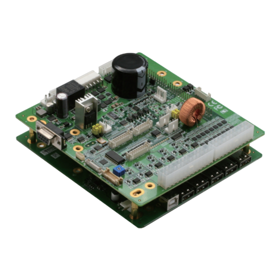
- Page 1 All manuals and user guides at all-guides.com AIOT- MSSP01 Mini SSP Vending Control Board User’s Manual 1 Last Updated: March 12, 2018...
- Page 2 All manuals and user guides at all-guides.com Copyright Notice This document is copyrighted, 2018. All rights are reserved. The original manufacturer reserves the right to make improvements to the products described in this manual at any time without notice. No part of this manual may be reproduced, copied, translated, or transmitted in any form or by any means without the prior written permission of the original manufacturer.
- Page 3 All manuals and user guides at all-guides.com Acknowledgement All other products’ name or trademarks are properties of their respective owners. ® is trademark of Advanced Micro Devices. Microsoft Windows is a registered trademark of Microsoft Corp. Intel, Pentium, Celeron, and Xeon are registered trademarks of Intel Corporation ...
- Page 4 All manuals and user guides at all-guides.com Packing List Before setting up your product, please make sure the following items have been shipped: Item Quantity AIOT-MSSP01 User’s Manual (in pdf) If any of these items are missing or damaged, please contact your distributor or sales representative immediately.
- Page 5 All manuals and user guides at all-guides.com About this Document This User’s Manual contains all the essential information, such as detailed descriptions and explanations on the product’s hardware and software features (if any), its specifications, dimensions, jumper/connector settings/definitions, and driver installation instructions (if any), to facilitate users in setting up their product.
- Page 6 All manuals and user guides at all-guides.com Safety Precautions Please read the following safety instructions carefully. It is advised that you keep this manual for future references All cautions and warnings on the device should be noted. Make sure the power source matches the power rating of the device. Position the power cord so that people cannot step on it.
- Page 7 All manuals and user guides at all-guides.com If any of the following situations arises, please the contact our service personnel: Damaged power cord or plug Liquid intrusion to the device iii. Exposure to moisture Device is not working as expected or in a manner as described in this manual The device is dropped or damaged Any obvious signs of damage displayed on the device...
- Page 8 All manuals and user guides at all-guides.com FCC Statement This device complies with Part 15 FCC Rules. Operation is subject to the following two conditions: (1) this device may not cause harmful interference, and (2) this device must accept any interference received including interference that may cause undesired operation.
- Page 9 All manuals and user guides at all-guides.com China RoHS Requirements (CN) 产品中有毒有害物质或元素名称及含量 AAEON Main Board/ Daughter Board/ Backplane 有毒有害物质或元素 部件名称 铅 汞 镉 六价铬 多溴联苯 多溴二苯醚 (Pb) (Hg) (Cd) (Cr(VI)) (PBB) (PBDE) 印刷电路板 ○ ○ ○ ○ ○ ○ 及其电子组件 外部信号...
- Page 10 All manuals and user guides at all-guides.com China RoHS Requirement (EN) Poisonous or Hazardous Substances or Elements in Products AAEON Main Board/ Daughter Board/ Backplane Poisonous or Hazardous Substances or Elements Hexavalent Polybrominated Polybrominated Component Lead Mercury Cadmium Chromium Biphenyls Diphenyl Ethers (Pb) (Hg)
-
Page 11: Table Of Contents
All manuals and user guides at all-guides.com Table of Contents Chapter 1 - Product Specifications..................1 Specifications ......................2 Chapter 2 – Hardware Information ..................4 Dimensions ....................5 Jumpers and Connectors ..................7 2.2.1 Main board layout ..................7 2.2.1 I/O board layout .................. - Page 12 All manuals and user guides at all-guides.com 2.3.2.5 RS232 (CN5) .................... 18 2.3.2.6 UART (CN6) ..................... 18 2.3.2.7 +24V Output (CN7) ................19 2.3.2.8 ADC (CN8) ....................20 2.3.2.9 8 Bit Digital External (CN10) ..............20 2.3.2.10 24V Vending Input (CN11) ..............21 2.3.2.11 Protocol A (CN12) .................
- Page 13 All manuals and user guides at all-guides.com Half Motor Configuration ..................33 Chapter 4 –Installation Guide ....................34 Firmware Installation ..................... 35 4.1.1 Prerequisites ....................35 4.1.2 Program Boot-loader ................35 Vending SDK Installation ..................43 4.2.1 Windows 10 Version .................. 43 4.2.2 Ubuntu 16.04 Xenial ................
-
Page 14: Chapter 1 - Product Specifications
All manuals and user guides at all-guides.com Chapter 1 Chapter 1 - Product Specifications... -
Page 15: Specifications
All manuals and user guides at all-guides.com Specifications External Connector USB 2.0 type A connector x 5 (via USB HUB) Micro USB 2.0 type B connector x 1 (USB HUB Host) Internal Connector MDB x 1 1-Wire 1-WIRE x 1 ... - Page 16 All manuals and user guides at all-guides.com Others Form Factor 150 mm x 140 mm Power Source 24V AC @ 50Hz, 24vDC Operating Temperature 0°C ~ 60°C Operating Humidity 0% ~ 90% relative humidity, non-condensing Certification CE, FCC ...
-
Page 17: Chapter 2 - Hardware Information
All manuals and user guides at all-guides.com Chapter 2 Chapter 2 – Hardware Information... -
Page 18: Dimensions
All manuals and user guides at all-guides.com Dimensions Chapter 2 – Hardware Information... - Page 19 All manuals and user guides at all-guides.com Chapter 2 – Hardware Information...
-
Page 20: Jumpers And Connectors
All manuals and user guides at all-guides.com Jumpers and Connectors 2.2.1 Main board layout Chapter 2 – Hardware Information... -
Page 21: I/O Board Layout
All manuals and user guides at all-guides.com 2.2.1 I/O board layout Chapter 2 – Hardware Information... -
Page 22: List Of Connectors
All manuals and user guides at all-guides.com List of Connectors Please refer to the table below for all of the board’s connectors that you can configure for your application 2.3.1 Mainboard Connector Index Connector Type Reference Function MCU-ICSP (TF)PIN HEADER.5*1P .180D.(M).2.54mm.DIP Vending detect (TF)WAFER BOX.6P .180D(M).DIP .2.0mm.w/LOCK CN4 CN6... -
Page 23: Mcu-Icsp (Cn1)
All manuals and user guides at all-guides.com 2.3.1.1 MCU-ICSP (CN1) Signal Description Signal Description MCLR# +3.3V PGED1 PGED1 2.3.1.2 Vending Detect (CN2) Signal Description Signal Description VEND_DET_IN VEND_DET_ALARM VEND_DETECT_VCC Chapter 2 – Hardware Information... -
Page 24: Rs-232 (Cn8)
All manuals and user guides at all-guides.com Vending Detection /Vending Detection Power MVC600 Default CST539 2.3.1.3 RS-232 (CN8) Signal Description Signal Description RS232_RXD RS232_TXD Chapter 2 – Hardware Information... -
Page 25: Usb2.0 (Cn9)
All manuals and user guides at all-guides.com 2.3.1.4 USB2.0 (CN9) Signal Description Signal Description 2.3.1.5 5V supply (CN10) Signal Description Signal Description Chapter 2 – Hardware Information... -
Page 26: I/O Board Connector Index
All manuals and user guides at all-guides.com 2.3.2 I/O board Connector Index Connector Type Reference Function Relay GPIO (TF)WAFER BOX.8P .180D(M).DIP .2.5mm.W/LOCK (TF)WAFER BOX.8P .180D(M).DIP .2.5mm.W/LOCK +12V output (TF)WAFER.2P .180D(M).3.96mm.W/LOCK POWER (TF) WAFER.6*1P .90D.(M).3.96mm.w/ Lock INPUT RS232 (TF)D-SUB CONNECTOR.9P .90D UART (TF)WAFER.4P .180D.(M).2.5mm.W/LOCK POWER DIP +24V output... - Page 27 All manuals and user guides at all-guides.com CN15 1-WIRE (TF)WAFER.4P .180D.(M).2.5mm.W/LOCK POWER DIP INTERFACE CN18 (TF)Board-Wire Connector.20P .180D(M).SMD.Pitch=1.25mm.W/Reinforc CN19 FULL MOTOR (TF)ATX POWER CONNECTOR.12P*2.180D(M) CN20 HALF MOTOR (TF)ATX POWER CONNECTOR.10P*2.180D.DIP Chapter 2 – Hardware Information...
-
Page 28: Relay Gpo (Cn1)
All manuals and user guides at all-guides.com 2.3.2.1 Relay GPO (CN1) Signal Description Signal Description DO_0 DO_1 DO_2 DO_3 RELAY_PWR RELAY_PWR RELAY_PWR RELAY_PWR RELAY POWER MODE SELECTION Default Chapter 2 – Hardware Information... -
Page 29: Mdb Master (Cn2)
All manuals and user guides at all-guides.com 2.3.2.2 MDB Master (CN2) Signal Description Signal Description MDB_SUPPLY EXT_24V_RTN MDB_RX MDB_TX Chapter 2 – Hardware Information... -
Page 30: Supply (Cn3)
All manuals and user guides at all-guides.com 2.3.2.3 +12V Supply (CN3) Signal Description Signal Description 2.3.2.4 Power Input (CN4) Signal Description Signal Description MDB_SUPPLY EXT_24V_RTN MDB_RX MDB_TX Chapter 2 – Hardware Information... -
Page 31: Rs232 (Cn5)
All manuals and user guides at all-guides.com 2.3.2.5 RS232 (CN5) Signal Description Signal Description RS232_RXD RS232_TXD 2.3.2.6 UART (CN6) Signal Description Signal Description +3.3V UART_TXD UART_RXD Chapter 2 – Hardware Information... -
Page 32: Output (Cn7)
All manuals and user guides at all-guides.com 2.3.2.7 +24V Output (CN7) Signal Description Signal Description MOTOR_PWR MOTOR POWER SELECTION MOTOR POWER MODE Default SELECTION Default Chapter 2 – Hardware Information... -
Page 33: Adc (Cn8)
All manuals and user guides at all-guides.com 2.3.2.8 ADC (CN8) Signal Description Signal Description ANALOG_IN1 ANALOG_IN2 ANALOG_IN3 ANALOG_IN4 2.3.2.9 8 Bit Digital External (CN10) Signal Description Signal Description 5V_CON_GPI1 5V_ CON _GPIO1 5V_ CON _GPI2 5V_ CON _GPIO2 5V_ CON _GPI3 5V_ CON _GPIO3 5V_ CON _GPI4 5V_ CON _GPIO4... -
Page 34: Vending Input (Cn11)
All manuals and user guides at all-guides.com 5V_ CON _GPI7 5V_ CON _GPIO7 5V_ CON _GPI8 5V_ CON _GPIO8 2.3.2.10 24V Vending Input (CN11) Signal Description Signal Description 24V_GPI1 24VIO_RTN_OPTO 24V_GPI2 24VIO_RTN_OPTO 24V_GPI3 24VIO_RTN_OPTO 24V_GPI4 24VIO_RTN_OPTO 24V_GPI5 24VIO_RTN 24V_GPI6 24VIO_RTN 24V_GPI7 24VIO_RTN 24V_GPI8... -
Page 35: Protocol A (Cn12)
All manuals and user guides at all-guides.com 2.3.2.11 Protocol A (CN12) Signal Description Signal Description MDBSLAVE_EXE_TX+_5V MDBSLAVE_EXE_TX-_5V MDBSLAVE_EXE_RX+_5V MDBSLAVE_EXE_RX-_5 PWR_IN_AC 2.3.2.12 DEX INTERFACE (CN13) Signal Description Signal Description DEX_DET DEX_DOUT DEX_RIN Chapter 2 – Hardware Information... -
Page 36: Keypad (Cn14)
All manuals and user guides at all-guides.com 2.3.2.13 Keypad (CN14) Signal Description Signal Description KEYPAD_0 KEYPAD_1 KEYPAD_2 KEYPAD_3 KEYPAD_4 KEYPAD_5 KEYPAD_6 KEYPAD_7 Chapter 2 – Hardware Information... -
Page 37: One Wire (Cn15)
All manuals and user guides at all-guides.com 2.3.2.14 One Wire (CN15) Signal Description Signal Description +3.3V 1-Wire DEVICE 2.3.2.15 8V Bit 5v Digital Internal IOS (CN16) Signal Description Signal Description 5V_HDR_GPI1 5V_HDR_GPIO1 5V_HDR_GPI2 5V_HDR_GPIO2 5V_HDR_GPI3 5V_HDR_GPIO3 5V_HDR_GPI4 5V_HDR_GPIO4 5V_HDR_GPI5 5V_HDR_GPIO5 5V_HDR_GPI6 5V_HDR_GPIO6 5V_HDR_GPI7... - Page 38 All manuals and user guides at all-guides.com 5V_HDR_GPI8 5V_HDR_GPIO8 Chapter 2 – Hardware Information...
-
Page 39: Lcd (Cn18)
All manuals and user guides at all-guides.com 2.3.2.16 LCD (CN18) Signal Description Signal Description 5V(Variable Resistor) DISPLAY_RS DISPLAY_R/W DISPLAY_EN LCD_CN_0 LCD_CN_1 LCD_CN_2 LCD_CN_3 LCD_CN_4 LCD_CN_5 LCD_CN_6 LCD_CN_7 Chapter 2 – Hardware Information... -
Page 40: Full Bridge Motor (Cn19)
All manuals and user guides at all-guides.com 2.3.2.16 Full bridge motor (CN19) Signal Description Signal Description MOTOR_RTN FULL_BRIDGE_1_BR FULL_BRIDGE_1_TR FULL_BRIDGE_2_BR FULL_BRIDGE_2_TR FULL_BRIDGE_3_BR MOTOR_RTN FULL_BRIDGE_3_TR FULL_BRIDGE_4_BR FULL_BRIDGE_4_TR FULL_BRIDGE_5_BR FULL_BRIDGE_5_TR MOTOR_VOLTAGE FULL_BRIDGE_1_TL FULL_BRIDGE_1_BL FULL_BRIDGE_2_TL FULL_BRIDGE_2_BL FULL_BRIDGE_3_TL MOTOR_VOLTAGE FULL_BRIDGE_3_BL FULL_BRIDGE_4_TL FULL_BRIDGE_4_BL FULL_BRIDGE_5_TL FULL_BRIDGE_5_BL Chapter 2 –... -
Page 41: Low Side Motor (Cn20)
All manuals and user guides at all-guides.com 2.3.2.17 Low side motor (CN20) Signal Description Signal Description LOWSIDE1_M-_1 LOWSIDE1_M-_2 LOWSIDE1_M-_3 LOWSIDE1_M-_4 LOWSIDE1_M-_5 LOWSIDE1_M-_6 LOWSIDE1_M-_7 LOWSIDE1_M-_8 MOTOR_RTN MOTOR_RTN LOWSIDE2_M-_1 LOWSIDE2_M-_2 LOWSIDE2_M-_3 LOWSIDE2_M-_4 LOWSIDE2_M-_5 LOWSIDE2_M-_6 LOWSIDE2_M-_7 LOWSIDE2_M-_8 MOTOR_RTN MOTOR_RTN MOTOR_RTN Chapter 2 – Hardware Information... -
Page 42: Home Sense (Jp5 Jp6)
All manuals and user guides at all-guides.com 2.3.2.18 Home sense (JP5 JP6) MOTOR RETURN GND HOME POSITION MODE SELECTION SELECTION Default Default Chapter 2 – Hardware Information... -
Page 43: Chapter 3 -Motor Setup
All manuals and user guides at all-guides.com Chapter 3 Chapter 3 –Motor Setup... -
Page 44: Introduction
All manuals and user guides at all-guides.com Introduction The AIOT-MSSP01 supports four types of motor configurations. Please refer to the following motor configuration setting information. Full Bridge Motor Configuration Chapter 3 – Motor Setup... -
Page 45: Low Side Motor Configuration
All manuals and user guides at all-guides.com Low Side Motor Configuration High Side Motor Configuration Chapter 3 – Motor Setup... -
Page 46: Half Motor Configuration
All manuals and user guides at all-guides.com Half Motor Configuration Chapter 3 – Motor Setup... -
Page 47: Chapter 4 -Installation Guide
All manuals and user guides at all-guides.com Chapter 4 Chapter 4 –Installation Guide... -
Page 48: Firmware Installation
All manuals and user guides at all-guides.com Firmware Installation Please follow the steps below to install/update firmware. 4.1.1 Prerequisites Install software – MPLAB IPE. To download, use the following link: http://microchip.wikidot.com/ipe:installation Install toolchain – MPLABX-v3.45-windows-installer 4.1.2 Program Boot-loader Step 1: Connect ICD 3 to the target board and apply power to the board. Chapter 4 –... - Page 49 All manuals and user guides at all-guides.com Step 2: Connect ICD3 device with the board and then plug in power Chapter 4 – Installation Guide...
- Page 50 All manuals and user guides at all-guides.com Step 3: Launch MPLAB IPE application Chapter 4 – Installation Guide...
- Page 51 All manuals and user guides at all-guides.com Step 4: Select the following options. Family: Please chose 32-bit MCUs (PIC32) Device: Please select PIC32MX795F512L Tool: Please select ICD 3 (with appropriate serial number) Microchip IPE initial screen Chapter 4 – Installation Guide...
- Page 52 All manuals and user guides at all-guides.com Step 5: After selecting the connect button to connect to the target board, the following screen will appear. Chapter 4 – Installation Guide...
- Page 53 All manuals and user guides at all-guides.com Step 6: Please click on “Browse” and locate the firmware hex file from source side in order to load Hex file. You will then see an acknowledge message in MPLAB IPE as shown below. Chapter 4 –...
- Page 54 All manuals and user guides at all-guides.com Step 7: Please click on the Program button. After successfully programming, you will see the screen shown below. Chapter 4 – Installation Guide...
- Page 55 All manuals and user guides at all-guides.com The HEX file has been successfully loaded to MCU PIC32. Microchip IPE Hex file loaded screen Chapter 4 – Installation Guide...
-
Page 56: Vending Sdk Installation
All manuals and user guides at all-guides.com Vending SDK Installation 4.2.1 Windows 10 Version Please follow the steps below to install supporting software programs before installing Intel_Intelligent_Vending_Sample_Application.exe. Step 1 Install QT 5.8 https://download.qt.io/official_releases/qt/5.8/5.8.0/ qt-opensource-windows-x86-msvc2015-5.8.0.exe Step 2 Update the PATH environment variable to include needed QT and Axis2C runtime binaries. -
Page 57
All manuals and user guides at all-guides.com c:\Qt\Qt5.8.0\5.8\msvc2015\plugins\sqldrivers c:\Qt\Qt5.8.0\5.8\msvc2015\plugins\mediaservice c:\Qt\Qt5.8.0\5.8\msvc2015\plugins\platforms C:\Users\
\AppData\Local\Intel_Corpora tion\Intel(R) Intelligent Vending Sample Application\API\Bin\Windows\axis2c\lib Remark: If there is no button to add each line and only a single textbox exists then add all paths separated by ; For example: ;c:\Qt\Qt5.8.0\5.8\msvc2015\bin;c:\Qt\Qt5.8.0\5.8\msv c2015\plugins\sqldrivers;c:\Qt\Qt5.8.0\5.8\msvc2015\plugins\mediaservice;c:\Qt\Qt5.8. -
Page 58
All manuals and user guides at all-guides.com Use the prebuilt package at ftp://sourceware.org/pub/pthreads-win32 and download the file pthreads-w32-2-9-1-release.zip. Step 4.3 After extracting the folder, copy Pre-built2/dll/x86/pthreadVC2.dll to your Mosquitto install directory. Step 5 For OpenSSl, you can copy libeay32.dll and ssleay32 dlls from the Vending SDK install directory C:\Users\
\AppData\Local\Intel_Corpora tion\Intel(R) Intelligent Vending Sample Application\API\Bin\Windows... -
Page 59: Ubuntu 16.04 Xenial
All manuals and user guides at all-guides.com 4.2.2 Ubuntu 16.04 Xenial Please make sure you have a working Internet connection and follow the steps below. Step 1 Copy the Ubuntu_16.04_Xenial_Release folder to your Ubuntu machine. Step 2 Open a terminal and execute: sudo su Step 3 In the terminal change directories to your copy of the Ubuntu_16.04_Xenial_Release folder Step 4 In the terminal execute: chmod +x install.sh... - Page 60 All manuals and user guides at all-guides.com Step 11 After the above sql file has been installed execute exit to exit. In the terminal execute: cd /usr/local/bin. Utilize any of the Start*.sh files to start the test apps, VendingDemo, Telemetry. In the terminal execute: cd /usr/local/bin.
-
Page 61: Update Vending Sdk For Ubuntu 16.04 Xenial
All manuals and user guides at all-guides.com 4.2.3 Update vending SDK for Ubuntu 16.04 Xenial If you already have the SDK installed on Ubuntu 16.04 Xenial, please follow the steps below to upgrade an existing system. Step 1 Copy the Ubuntu_16.04_Xenial_Release folder to your Ubuntu machine. Step 2 Open a terminal and execute: sudo su Step 3 In the terminal change directories to your copy of the Ubuntu_16.04_Xenial_Release folder... -
Page 62: Update Db In Vending Sdk For Ubuntu 16.04 Xenial
All manuals and user guides at all-guides.com 4.2.4 Update DB in vending SDK for Ubuntu 16.04 Xenial If the upgrade requires a DB update, please follow the steps below. Step 1 In the terminal execute: mysql -u root –p Step 2 When prompted enter root123 as the password. Step 3 Execute: source intel_vending.sql Step 4 After the above sql file has been installed execute exit to exit.