
Related Manuals for Mitsubishi Electric FX3S-10MR/ES


Summary of Contents for Mitsubishi Electric FX3S-10MR/ES
- Page 1 All manuals and user guides at all-guides.com PROGRAMMABLE LOGIC CONTROLLER MODEL FX3S QUICK START MANUAL Mitsubishi Electric Automation, Inc.
-
Page 2: Table Of Contents
4.3 POWER SUPPLY SPECIFICATIONS AND WIRING DIAGRAM .............9 4.4 INPUT SPECIFICATIONS AND WIRING DIAGRAM ..9 4.5 PULSE CATCH (M8170 TO M8175) ........10 4.6 HIGH SPEED COUNTERS SPECIFICATIONS AND WIRING ..............11 4.7 OUTPUT SPECIFICATIONS AND WIRING ...... 11 Mitsubishi Electric Automation, Inc. -
Page 3: Introduction
It is important to follow all precautions for Effective September 2014 personal safety. Specifications are subject to change without notice. © 2013 MITSUBISHI ELECTRIC CORPORATION DANGER: STARTUP AND MAINTENANCE PRECAUTIONS • Do not touch any terminal while the PLC’s power is on. Doing so 1.1 AVAILABLE MODELS... -
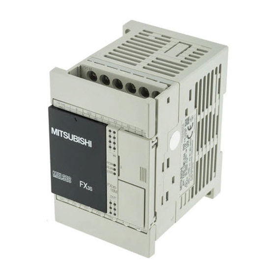
Page 4: Front Panel
[4] Terminal cover A protective terminal cover (refer to the following drawing) is fitted to the lower stage of each terminal block. The cover prevents fingers from touching terminals, thereby improving safety. Mitsubishi Electric Automation, Inc. -
Page 5: Dimensions
For more details please W1: mm (inches) Weight: kg (lbs) Model Number W: mm (inches) Direct mounting contact Mitsubishi Electric at [email protected] Approx hole pitches n REQUIREMENT FOR COMPLIANCE WITH EMC DIRECTIVE FX3S-10MR/ES 60 (2.37") 52 (2.05") -
Page 6: Mounting Instructions
Class D grounding (grounding resistance: 100Ω or less)*3 Working Free from corrosive or flammable gas and excessive conductive Atmosphere dusts Working <2000m *4 Altitude Mitsubishi Electric Automation, Inc. -
Page 7: Terminal Block Layout
COM1 COM2 [•] Vacant terminal Output terminals -30MR/ES (Do not use.) connected to COM4 Y4 COM3 • COM0 COM1 COM2 Y10 COM4 Partition 24 V DC service Output terminals Common terminal power supply (4 points/common terminal) Mitsubishi Electric Automation, Inc. -
Page 8: Specifications And Wiring
• Perform class D grounding (grounding resistance: 100Ω or less) to LTD (JST) the grounding terminal on the main unit with a wire 2 mm² or thicker. • Do not use common grounding with heavy electrical systems. Mitsubishi Electric Automation, Inc. -
Page 9: Grounding
Emer- gency stop Main unit Fuse Class D grounding power supply 1. Input impedance. 2. The “24V” and “0V” terminals are located on the output terminal side. Power supply for loads connected to PLC output terminals Mitsubishi Electric Automation, Inc. -
Page 10: Pulse Catch (M8170 To M8175)
EXAMPLES OF EXTERNAL WIRING It is recommended to use shielded twisted-pair cables for connection cables. Ground the shield of each shielded cable only on the PLC side. Three- X000 wire * The grounding resistance should be 100 or less. Mitsubishi Electric Automation, Inc. -
Page 11: High Speed Counters Specifications And Wiring
Ground the shield Input Circuit Insulation Mechanical insulation of each shielded cable only on the PLC side. Input Operation Display LED on panel lights when power is applied to relay coil Mitsubishi Electric Automation, Inc. -
Page 12: Programming Using Gx Works2
Expansion board -232-BD A short-circuit at a load connected to an output terminal could cause RS-232C burnout at the output element or the PCB. To prevent this, a protection fuse should be inserted at the output. Mitsubishi Electric Automation, Inc. -
Page 13: Installing The Usb Driver
Select “Include subfolders” . POINT Considerations when installing USB driver: When the Windows can’t verify the publisher of this driver software screen is displayed during the installation, select “Install this driver software anyway” . Mitsubishi Electric Automation, Inc. -
Page 14: Installing Gx Works2
Notice: Reprinting or reproducing the part or all of the contents of this document in any form for any purpose without the permission of Mitsubishi Electric Corporation is strictly forbidden. • Although we have made the utmost effort to follow the revisions of the software and hardware, in some cases, unsynchronized matter may occur. -
Page 15: Starting And Exiting Gx Works2
• Error codes for CPU module communication Title bar • Changes from GX Developer Menu bar • List of shortcut keys Toolbar • Registered Trademarks and Trademarks Element Selection window • FX manuals Navigation window Work window Docked window Status bar Mitsubishi Electric Automation, Inc. -
Page 16: Operation
PLC (refer to the right figure). Turn the switch to RUN, and the PLC will start. Turn it to STOP, and the PLC will stop. Communication Positioning mark cable Mitsubishi Electric Automation, Inc. - Page 17 RUN/STOP switch. automatically. If there are no problems with the hardware, parameters *1. X000 to X005 in FX3S-10MR/ES, X000 to X007 in FX3S-14MR/ES, or program, the PLC will start and the RUN command is given (RUN and X000 to X013 in FX3S-20MR/ES.
-
Page 18: Maintenance
3. If the ERR LED does not go off even after Check that dust or conductive dust has not entered the panel. the measures stated in (1) and (2) are taken, contact Mitsubishi Electric at Check for loosening of wiring and other abnormalities. [email protected]. - Page 19 MITSUBISHI ELECTRIC AUTOMATION, INC. 500 Corporate Woods Parkway, Vernon Hills, IL 60061 Ph 847.478.2100 • Fx 847.478.2253 us.MitsubishiElectric.com/fa/en/support January, 2016 • ©2016, Mitsubishi Electric Automation, Inc. • Specifications subject to change without notice. • All rights reserved AZ-JY997D48601C-A Mitsubishi Electric Automation, Inc.