
Related Manuals for Sanyo HECSA5000


Summary of Contents for Sanyo HECSA5000
- Page 1 FILE No. Chair Type Massager HEC-DR5000 SERVICE MANUAL (GENERAL) (Massager Lounger) SM6510488-00 REFERENCE NO. - 1 -...
- Page 2 Specifications HEC-DR5000 (GENERAL) Power source AC Local voltage 50/60 Hz Power consumption 290 W Rated time 30 minutes (MANUAL COURSE) Approx. 15 minutes Timer (WHOLE BODY SENSOR AUTOMATIC COURSE) Approx. 15 minutes (maximum Approx. 20 minutes) (AUTOMATIC COURSE) Approx. 15 minutes (maximum Approx. 20 minutes) 730 mm[width] x 1,240 mm[depth] x 1,200 mm[height] * When not reclined (with foot rest retracted) Dimensions...
-
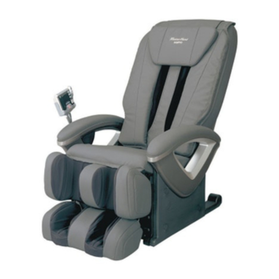
Page 3: Name/Function Of Each Part
Name/Function of Each Part HEC-DR5000 (GENERAL) Head cover Senser Back rest Remote control Massage hands Stand Back pad Arm rest Seat cover ( 2 Air bags ) Foot rest Reclining motors ( 18 Air bags ) Control unit Air pump & Solenoids Massage unit Tapping motor Massage motor... -
Page 4: Wiring Diagram (For Low Voltage)
Wiring Diagram (for LOW voltage) HEC-DR5000 (GENERAL) CN931 Limit Switch(UPPER) CN904 Printed board (Strength) (Strength Pulse) Volume Rotary CN903 CN902 (Pressure) CN905 CN911 Motor(Elevation) Printed board Printed board (Elevation Pulse) Motor(Strength) (Massage Pulse) Motor(Massage) CN906 CN921 CN901 Motor(Tapping) Printed board (Tapping Pulse) Reclining Motor(Foot Rest) Reclining Motor (Back Rest) -
Page 5: Wiring Diagram (For High Voltage)
Wiring Diagram (for HIGH voltage) HEC-DR5000 (GENERAL) CN931 Limit Switch(UPPER) CN904 Printed board (Strength) (Strength Pulse) Volume Rotary CN903 CN902 (Pressure) CN911 CN905 Motor(Elevation) Printed board Printed board (Elevation Pulse) Motor(Strength) (Massage Pulse) Motor(Massage) CN906 CN921 CN901 Motor(Tapping) Printed board (Tapping Pulse) Reclining Motor(Foot Rest) Reclining Motor (Back Rest) - Page 6 Air Wiring HEC-DR5000 (GENERAL) Air pump compressing decompressing Air tank 1 Air bag 5 Air bag Exhaust Exhaust (Foot shiatsu, middle) (Leg pinching) 1 Solenoid 5 Solenoid (Foot shiatsu, middle) (Leg pinching) 1 Air bag 5 Air bag (Foot shiatsu, middle) (Leg pinching) 2 Air bag 6 Air bag...
- Page 7 Air Massage HEC-DR5000 (GENERAL) Structure of air massaging component for lower extremites Air hoses Air tank Solenoids Air pump Photo-2 Photo-1 1, Foot shiatsu, middle 5, Leg pinching 2, Foot shiatsu, back and forth 6, Foot pinching, outsid 3, Leg shiatsu, upper 7, Foot pinching, insaide 4, Leg shiatsu, lower 8, Thigh, right, left...
- Page 8 Massage Motors HEC-DR5000 (GENERAL) Strength motor Massage motor Elevation motor Tapping motor 1, Tapping motor This motor rotates to move the massage balls upward and downward alternately via the driving belt coupled to the motor. (The motor revolutions is adjustable in three steps so that the tapping frequency can be changed over to approximately 300,390,480,540 and 600 cycles/minute.) 2, Massage motor This motor rotates to move the massage balls crosswise via the driving belt and gear...
- Page 9 Massage Motors HEC-DR5000 (GENERAL) Shoulder Gripping & Massaging With the aid of a massage hand unit with a joint which moves freely like a thumb, a massaging technique called "Grip/Grasp/Massage/Knead" for gripping and massaging the muscles of shoulders has been reproduced. This massaging technique has been reproduced by way of gripping the shoulders from above while projecting the massage hands greatly together with a massage unit at the back (maximum projection of massage hands: approx.
- Page 10 Operation of Stiffness Detecting Sensor HEC-DR5000 (GENERAL) The sensor employs two types of sensors; an photo sensor and an electrical skin resistance sensor for monitoring two physiological factors (pulse rate and perspiration respectively). If stiffened position is subjected to stimulation of massage, the pulse rate and perspiration will change accordingly.
- Page 11 Operation of Body Contour Sensor HEC-DR5000 (GENERAL) Detects a pressure applied to the massasing balls for automatic adjustment to their best position. Detects a pressure applied to the massasing balls for measuring spine curving to find out body contour and shoulder position. Corrects the positions automatically if the posture varies when reclining a seat.
-
Page 12: Error Message Indication (In Service Mode)
Error message indication (in Service Mode) HEC-DR5000 (GENERAL) *Abnormal indications detected during operation are stored in a memory up to seven. Seven abnormal indications stored can be confirmed in the service mode (Older indications than the seven abnormal indications will be deleted sequentially). To change over to the service mode, turn ON the POWER switch at the rear of the massager while simultaneously pressing the OPERATION ON/OFF on a remote controller. - Page 20 Air-Bag Operation Confirmation Procedure HEC-DR5000 (GENERAL) Start-up of Examination Mode Turn ON the POWER switch at the rear of the massager while simultaneously pressing the POSITION ADJUST "UP" and "DOWN" buttons on the remote controller (This operation should be started with the POWER switch turned OFF). When the examination mode is started up, both a backrest and a foot rest move slightly and come to a stop.
-
Page 21: Replacement Procedure
Replacement Procedure HEC-DR5000 (GENERAL) (1) Replacement of PCBs (main) 5, Remove two cover (PCB) set screws and take & (power) off latches of ribs at the rear of the cover. 1, Take off four thread caps on an arm rest Photo-3 (left). - Page 22 Replacement Procedure HEC-DR5000 (GENERAL) (2) Replacement of Solenoid 1, Remove one cord holder set screw and unfix Insulator two remote controller cords. Photo-5 Solenoid 2, Take off four thread caps on the arm rest (right). Photo-5 3, Remove four elbow rest set screws and take off the arm rest (right).
- Page 23 Replacement Procedure HEC-DR5000 (GENERAL) (4) Replacement of Reclining Motor (5) Replacement of Power Switch and Current Fuse 1, Take off the arm rest (left). Photo-1 1, Take off the arm rest (right). Photo-5 2, Take off the arm rest (right). Photo-5 2, Remove each cord processing and 3, Disconnect each cord processing and cords.
- Page 24 Replacement Procedure HEC-DR5000 (GENERAL) (6) Replacement of Remote Control (7) Replacement of Sensor 1, Remove each cord processing and 1, Remove each cord processing and disconnect the cords. disconnect the cords. 2, Remove nine remote control case set screws 2, Remove two sensor case set screws and and take off a remote control case (lower).
- Page 25 Replacement Procedure HEC-DR5000 (GENERAL) (8) How to Remove A Massage Unit 1, Remove four cover(back cover) set screws If the massage unit does not move upwards when the power is turned on, turn a pulley and take off a cover(back cover). Photo-16 (elevation) clockwise to move the massage unit to the top position.
- Page 26 Replacement Procedure HEC-DR5000 (GENERAL) (9) How to Reassemble the Massage Unit 8, Turn the pulley (evevation) clockwise, move the 1, Tape a lever of a micro switch. For the purpose of preventing the lever of the massage unit upwards, and take off a driving micro switch from being deformed or wheel from a back frame guide.
- Page 27 Replacement Procedure HEC-DR5000 (GENERAL) (10) Replacement of PCB (strength pulse) (12) Replacement of PCB (Massage) 1, Disconnect the connector CN931 of the PCB 1, Disconnect five PCB (massage) connectors. (strength pulse). Photo-23 Photo-25 2, Remove one PCB (strength pulse) set screw 2, Remove two PCB (massage) set screws and and take off the PCB (strength pulse).
- Page 28 Replacement Procedure HEC-DR5000 (GENERAL) (14) Replacement of PCB (Tapping pulse) and PCB(elvation pulse) 4, Disconnect the belt (elevation). Photo-29 1, Disconnect the connector CN921 of the PCB 5, Remove two gear box (elevation) set screws, (tapping pulse). Photo-27 2, Remove one PCB (tapping pulse) set screw slide the gear box outwards, and turn it and take off the PCB (tapping pulse).
- Page 29 Replacement Procedure HEC-DR5000 (GENERAL) (16) Replacement of Motor (Tapping) * Take off the motor (massage) and motor 5, Remove two holder (shaft tapping) set (elevation) in advance. serews. Photo-33 1, Disconnect the belt (tapping). Photo-31 6, Remove ring E 10. Photo-33 2, Remove ring E 10 and pull out pulley 7, Remove two motor (tapping) set screws.
- Page 30 2, Loosen a nut off volume fixation and take off the volume rotary. Photo-36 3, Disconnect the volume rotary. Photo-36 Cam set screw Cord bushing Photo-38 Cam (pressure) Volume rotary Photo-36 SANYO Electric Co.,Ltd - 30 - Jul./2005 Printed in Japan Osaka, Japan...
- Page 31 This file has been downloaded from: www.UsersManualGuide.com User Manual and User Guide for many equipments like mobile phones, photo cameras, monther board, monitors, software, tv, dvd, and othes.. Manual users, user manuals, user guide manual, owners manual, instruction manual, manual owner, manual owner's, manual guide, manual operation, operating manual, user's manual, operating instructions, manual operators, manual operator, manual product, documentation manual, user maintenance, brochure, user reference, pdf manual...